LX6V-4AD/4DA
Introductions
LX6V-4DA (4-channel analog output) module is used to treat voltage, current and other analog signal output. The module is adapted to LX6 series PLC and LX6V-EM□-ECAT module device.
Supported software version (Wecon PLC Editor2): 2.3.118 and above;
Supported firmware version: 2.198 and above.
Naming rules
| LX6V | - | 4 | AD |
|---|---|---|---|
| ① | ② | ③ |
① Series
② Number of channels
③ AD: Analog input; DA: Analog output
| Model | Description |
|---|---|
| LX6V-4AD | 4-channel analog input module |
| LX6V-4DA | 4-channel analog output module |
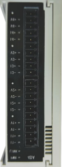
Terminal Description
The terminal line arrangement of the analog expansion module is as follows:
| Module model | Terminal arrangement |
|---|---|
| LX6V-4AD |  |
| LX6V-4DA | 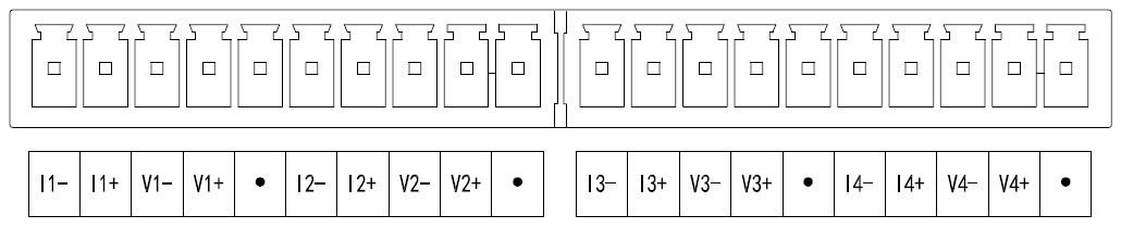 |
Indicator lamp
4AD indicator lamp function description
| Indicator lamp | Description |
|---|---|
| PWR | Expansion module is normally on when power-on. |
| LINK lamp | Expansion module and PLC communication indicator lamp; ON: Data interaction executing; OFF: Data interaction abnormal, stop or fail. |
| VIn- | Defined as an ERR lamp, On: Indicate over-range; Off: In normal status; Flashing: Channel without calibration. |
| Vn+/In+ | Defined as a channel enable indicator light; ON: Indicate that the channel is enabled; OFF: Indicate that the channel is disabled. |
4DA LED Function Description
| Indicator lamp | Description |
|---|---|
| PWR | Expansion module is normally on when power-on. |
| LINK lamp | Expansion module and PLC communication indicator lamp; ON: Data interaction executing; OFF: Data interaction abnormal, stop or fail. Normally on, data interaction executing |
| VIn-/In- | Defined as an ERR lamp, Vn-On: Indicate over-range or DAV short-circuit; In- On: Indicate over-range or DAI open circuit; Vn-/In- Flashing: Channel without calibration. |
| Vn+/In+ | Defined as a channel enable indicator light; ON: Enabled; OFF: Disabled. |
Parameter specifications
AD input specifications
| Project | Specification requirements |
|---|---|
| Input type | Analog input |
| Input circuit composition | 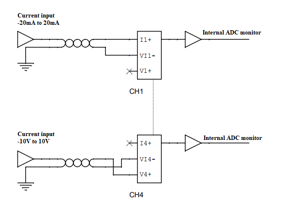 |
| Input mode | Voltage/current |
| Input channel | 4 |
| Resolution | 1/16384 (14bit) |
| Voltage input range | -10V-10V |
| Voltage input impedance | 190kΩ |
| Current input range | 4mA-20mA, -20mA-20mA |
| Current input impedance | 250Ω |
| Comprehensive precision | ±1% |
| Conversion speed | 1ms |
| Power supply | Interface power supply, DC 24V±10%, 55mA |
DA output specifications
| Project | Specification requirements |
|---|---|
| Output type | Analog output |
| Output circuit composition |  |
| Output mode | Voltage/current |
| Output channel | 4 |
| Resolution | 1/20000, hardware can meet 16bit resolution |
| Voltage output range | -10V-10V |
| Voltage output load | ≥2KΩ |
| Voltage output diagnosis | Support non-zero voltage output short-circuit detection with about 14mA overcurrent protection |
| Current output range | 0-20mA, 4-20mA |
| Current output load | ≤500Ω |
| Current output diagnosis | Support non-zero current output open circuit detection |
| Comprehensive precision | ±1% |
| Conversion speed | Approximately 1ms |
| Power supply | Interface power supply, DC 24V±10%, 125mA |
Environment specifications
| Project | Specification requirements |
|---|---|
| Usage environment | No corrosive or combustible gas No large amount of conductive dust |
| Storage temperature | -20℃ to 70℃ |
| Storage humidity | 5-95%RH (No condensation) |
| Environment temperature (Running) | 0℃-60℃ |
| Environment humidity (Running) | 5-95%RH (No condensation) |
| Installation | After being installed on the host, it is installed on the rail through the fastener. |
| Appearance size | 91*28.1*95mm |
| Impact/vibration resistance | Compliant with JISC 0040 standard |
| Grounding | Cannot be co-located with the high-voltage system |
| Shell material | Plastic |
| Terminal type | Motherboard is with 3.5mm pitch black terminal seat |
| Cooling | Natural ventilation |
Software specifications
4AD
| Project | Specification requirements |
|---|---|
| Independent channel enable configuration | Support |
| Conversion mode configuration | -10V to 10V, 4 to 20mA, -20mA to 20mA |
| Filter parameter configuration | Set the range from 0 to 255, unit: ms |
| Overrun detection | Support |
| Converse digital range configuration | -10000 to 10000, 0 to 20000, -20000 to 20000 |
| Sampling time | 4 channels 1ms |
| Sample refresh | Refresh asynchronously according to sampling time, which is not required synchronous refresh according to bus cycle. |
4DA
| Project | Specification requirements |
|---|---|
| Independent channel enable configuration | Support |
| Conversion mode configuration | -10V to 10V, 4 to 20mA, 0mA to 20mA |
| Output status configuration on downtime | Output clear, Output hold, Output preset |
| Output preset configuration after downtime | Support |
| Converse digital range configuration | -10000 to 10000, 0 to 20000 |
| Stop mode | Output by failure down status mode and preset value, no more refreshing |
Instructions for use
The parameter configuration interface is as below:

PLC Expansion Module Configuration Description (The following takes the model LX6V-4AD as an example to explain).
① Double-click the expansion module configuration to open the configuration interface;
② Adding new modules according to the model and position of the current module connected host;
③ Double-click the module in the current machine slot to open the parameter configuration interface;
Parameter configuration interface
4AD module configuration

① Enable channels: It can be set whether to enable the current expansion module channel;
② Conversion mode: The default setting is ADV conversion mode, the measurement range is-10V-10V (-10000-10000);
Supported conversion modes:
-10V-10V (-10000-10000);
4mA-20mA (0-20000);
-20mA-20mA (-20000-20000).
③Filtering time: Support 1-255ms, used to reduce the fluctuation of channel output data, the default filtering time is 4ms. Please adjust the channel output data according to the requirements of the actual application scenario
to select the appropriate filtering time;
④ Enable calibration: When the actual analog input of the module channel deviates greatly from the measured channel value of the module, it can be used to improve the measurement precision and accuracy.
For modules with calibration enabled, the channel value is calculated as follows: Actual channel value = digital*gain+offset, e.g.:
When the channel input analog is 10000mV, the measured digital is 9950, and the actual channel value should be 10000;
When the channel input analog is -10000mV, the measured digital is-9950, and the actual channel value should be -10000;
Assume gain as a and offset as b
 ; the result is
 .
.
The derivation formula is as follows:
Gain = (Actual input analog 1-actual input analog 2)/ (Expansion module measured digital 1-Expansion module measured digital 2)
Offset = actual channel value-digital*gain
With the above formula, the gain and offset values can be derived to calibrate the module to improve the accuracy and stability of the measurement. When performing calibration, it is necessary to select the appropriate
parameters and methods, ensuring accurate and reliable measurement results.
I/O mapping

By default, channels are mapped to R device according to the current number of module channels. The figure below shows modules CH1-CH4 mapped to R0-R3 device.
4DA module configuration

① Enable channels: It can be set whether to enable the current expansion module channel;
② Conversion mode: The default setting is DAV conversion mode, and the output range is-10V-10V (-10000-10000);
Supported conversion modes: -10V-10V (-10000-10000), 4mA-20mA (0-20000), -20mA-20mA (-20000-20000)
③ Output status after stopping: When the PLC is in the stop status, the output status of the module channel mainly includes the following three types:
Output cleared: When PLC STOP, the output voltage/current of the module channel is 0V/0uA;
The output holds: When PLC STOP, the module channel output holds the digital output value set by the corresponding channel in the current I/O mapping device;
Output presets: When PLC STOP, the module channel outputs the voltage/current value corresponding to the preset digital or the preset analog.
④ Enable calibration: When the actual output analog of the module channel deviates greatly from the analog measured by the high-precision multimeter, it can be used to improve the output precision and accuracy.
For modules with calibration enabled, the channel value is calculated as follows: Channel input digital=actual voltage output corresponding digital*gain+offset
For example:
When the input digital of the channel is 10000, the measured output voltage of the channel by the high-precision multimeter is 9950mV (the corresponding digital is 9950);
When the channel input digital is -10000, the measured output voltage of the channel by the high-precision multimeter is -9950mV (the corresponding digital is-9950);
Assume gain as a and offset as b
 the result is
The derivation formula is as follows:
Gain = (channel input digital quantity 1-channel input digital quantity 2)/ (multimeter measured digital 1-multimeter measured digital 2)
Offset=channel input digital-actual voltage output corresponding digital *gain
I/O mapping
By default, channels are mapped to R device according to the current number of module channels. The figure below shows modules CH1-CH4 mapped to R0-R3 device.

Click PLC download and check the extension function the interface in turn. Click Execute, and download the extension module configuration to PLC.
EtherCAT IO Slave Configuration
4AD Module Startup Parameters
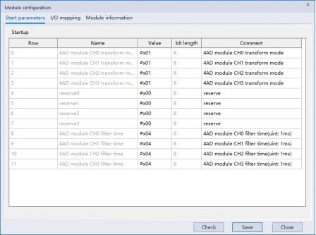
① 4AD module CHx transform mode: Used to specify the current channel CHx (x∈[0, 3]) conversion mode:
Supported conversion modes:
0: Not enabled
1: -10V-10V (-10000-10000)
2: 4mA-20mA (0-20000)
3: -20mA-20mA (-20000-20000)
② 4AD module CHx filter time: Used to specify the current channel CHx (x ∈ [0, 3]) filtering time, range: 0-255, unit: ms
③ Reserve: reserve, not in use for the time being
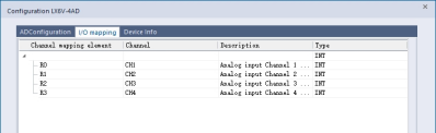
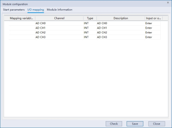
I/O mapping: Modules CH0 to CH3 can be mapped into variables/device, for example, the figure below CH0 to CH3 channel values was mapped into D0 to D3 device.
4DA startup parameters

① 4DA module CHx transform mode: For specifying the current channel CHx (x∈ [0, 3]) conversion mode;
Supported conversion modes:
0: Not enabled
1: -10V-10V (-10000-10000)
2: 4mA-20mA (0-20000)
3: -20mA-20mA (-20000-20000)
② 4DA module CHx stopmode: For specifying the current channel CHx (x∈ [0, 3]) stop mode;
Supported stop modes:
0: Output cleared
1: Output hold
2: Output preset value
③ 4DA module CHx stopvalue: Used to specify that the current channel CHx (x∈ [0, 3]), which is set to the output digital in the preset value mode. When 4DA module CHx stopmode is set to 2, if PLC STOP or EtherCAT is disconnected, module channel will output the digital specified by this parameter.
I/O mapping: Modules CH0 to CH3 can be mapped into variables/device, for example, the figure below CH0 to CH3 channel values was mapped into D0 to D3 device.
