LX3V-4ADI
1 Installation Instructions
Before installation, it is necessary to ensure that the associated equipment of the PLC host and the terminal of the BD module are reliably powered off.
This module comes with two standard terminals; please plug the terminals into the module terminals after wiring. Confirm the installation of host, module and wiring are correct and then power on.
Caution:
- The input must not exceed the absolute maximum (-2mA/30mA) or cause the module to be damaged;
- To install the function expansion board firmly and fix it on the PLC, poor contact may cause malfunction;
- The fastening torque is 0.3-0.6N.m. Firmly screw down to prevent malfunctions;
- The PLC main unit of the LX3V can only use one BD module. Don’t try to use two or more BD modules (these BD modules will not work);
- When mounting module to PLC, all the lights are blinking after power ON PLC, it means this PLC can’t support it, please purchase new PLC.
Warnings:
Cut off the electricity before installation/disassembly of the unit or connection of wires onto the unit, to prevent electric shock or product damage.
2 Features of LX3V-4ADI-BD
- It could use LX3V-4ADI-BD to add 4 analog input points. It is internally installed in the top of PLC, thus it is not necessary to change the PLC’s installation area.
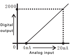
- The digital analog conversion of the LX3V-4ADI-BD module is the voltage inputs (4~20mA), and the data of all the channels after conversion are stored inside a special digital memory, but the converted characteristics of the analog data cannot be adjusted. The allocation of the relevant channel addresses is in the following table.
| Address | Instructions | Address | Instructions | |
| M8112 | CH1:flag of the input mode OFF: Current input mode | ON: Disabled | D8112 | Digital value of CH1 |
| M8113 | CH2: flag of the input mode OFF: Current input mode | D8113 | Digital value of CH2 | |
| M8114 | CH3: Flag of the output mode OFF: Current input mode | D8114 | Digital value of CH3 | |
| M8115 | CH4: flag of the output mode OFF: Current input mode | D8115 | Digital value of CH4 | |
3 Dimension
| Input current ranges: 4~20mA | |||
| Ii1+ | The anode of CH1 current input | Ii3+ | The anode of the CH3 current input |
| Ii1- | The cathode of CH1 current input | Ii3- | The cathode of the CH3 current input |
| ▪ | Disconnect | ▪ | Disconnect |
| Ii2+ | The anode of CH2 current input | Ii4+ | The anode of the CH4 current input |
| Ii2- | The cathode of CH2 current input | Ii4- | The cathode of the CH4 current input |

LED lights indicating:
- POW LED: Constantly ON when PLC power ON;
- COM LED: Lit when communicating PLC, OFF when timeout;
- CH1 LED: LED for CH1, constantly ON when analog signal in range, lit when analog signal out of range (4~20mA). OFF when M8112 turns ON.
- CH2 LED: LED for CH2, constantly ON when analog signal in range, lit when analog signal out of range (4~20mA). OFF when M8113 turns ON.
- CH3 LED: LED for CH3, constantly ON when analog signal in range, lit when analog signal out of range (4~20mA). OFF when M8114 turns ON.
- CH4 LED: LED for CH4, constantly ON when analog signal in range, lit when analog signal out of range (4~20mA). OFF when M8115 turns ON.
4 Specifications
- General specification: The same as the PLC main unit.(Please refer to the attached instructions supplied with the main unit of the PLC.)
- Power specification: Powered from inside of the programmable controller.
- Performance specifications
| Item | Specification |
| Power supply | 5VDC±10%, 70mA (Powered by PLC host) |
| Analog input (ADI) | |
| Analog input range | DC 4~20mA (input resistance 250KΩ). Absolute maximum input: -2mA, +30mA |
| Rated range | 4~20mA: 0~2000 |
| The maximum display range | -500~2048 |
| Resolution | 8uA[4mA ~20mA / 2000 ] |
| Precision | ±0.5% of full scale (4~20mA:±0.08mA) |
| AD conversion time | One PLC scanning cycle |
| Input characteristics |
|
| Insulation | No insulation in each PLC channel |
| Occupied points | None |
5 Wire Connection
Warning:
Make sure cut off the electricity before installation/disassembly, to prevent electric shock or product damages.
Caution:
- Please keep the signal cable from the high-voltage cable at lease 100mm.
- The shielding wire cable shall be grounded. But their grounding point can be the same with high-voltage lines.
- Never connect cable with forbidden size.
- Fix the cable, so that the stress does not act on the terminal board or the cable connection area.
- The screwing torque of the terminal is from 0.5 to 0.6N.m. Fasten tight to prevent malfunction.
- Keep the redundant terminals empty.
5.1 Applicable Cables
Use AWG25-16 to connect the output equipment
The maximal screwing torque is from 0.5 to 0.6N.m
The use of different types of cables might cause poor contact between the terminals. It is better to use pressed terminals.
| Line type | Cross sectional area(mm2) | End-of-pipe treatment |
|
| AWG26 | 0.1288 | Stranded cable: stripped jacket, rub Conductor, then connect the cable. Single-core cable: stripped jacket, Then connect the cable. | |
| ...... | ...... | ||
| AWG16 | 1.309 |
5.2 Current Input Mode

6 Example
The analog value (4~20mA) in each channel will be saved in system address (D8112, D8113). It will be saved automatically when “END”, and convert into digital value. Use CH1 and CH2 as example.
6.1 Basic program
Caution:
- Trigger M8122 and M8113, and set the characteristic of conversion in CH1 and CH2.
- Do not change the value of D8112 and D8113.
- Do not change the digital value of the D8112 or D8113 by operating the user program, programming tool, or graphical operator terminal after ADI performs A/D conversion.
Set channel 1 as current input (4~20mA)
Set channel 2 as current input (4~20mA)
Save the value of channel 1 to D0
Save the value of channel 2 to D2

- If the digital value is not stored in D0 or D2, D8112 and D8113, D8114 and D8115 can be used directly for both the set point and other instructions.
For example timer \ counter.
6.2 Application example
LX3V-4ADI-BD has no offset and gain function.
Caution:
- There are extra program for multiplication and division, so the real accuracy and resolution of AD conversion are different from product specifications;
- The range for analog output is constant;
Current input mode
In current input mode, it changes the analog value (4-20mA) to digital value (0-2000). If users need 4000-20000 digital range, it requires a conversion.
As following program shows, the digital value is saved in D8112 and D8113, because the digital range is changed from 0-2000 to 4000-20000, so the resolution of LX2AD2DA-BD is not 8uA.

Suppose the user needs 4000-20000, and save in D0, so D0=8*(D8112 or D8113) +4000, the program as following shows.
