

LX5V-2PT2ADV
1. Installation
- Before installation, it must be ensured that the PLC host and the related device of the BD module terminal wiring are powered off reliably. The module shell is inserted into the BD module slot of PLC host, and then locked with two standard screws for fixation.
- Two standard terminal heads are equipped with this Bd module. After connecting the wiring, insert them into its terminal. After confirming that the host, BD module, wiring, etc. are installed correctly, it can be powered on for use.
- ✎Note:
- The ADV input voltage cannot exceed the absolute maximum (-15V/+15V), otherwise the BD module will be damaged.
- Please install the BD module firmly and fix it on PLC. Poor contact may lead to failure.
- Tightening torque for fixing BD module or PLC top cover is 0.3N.m to 0.6N.m. Please tighten it firmly to avoid malfunction.
- You can only use one LX5V-2PT2ADV-BD on the PLC main unit of LX5 series.
- Warning: Cut off the power before installing, removing or wiring the BD module to avoid electric shock or product damage.
2. Appearance and terminal
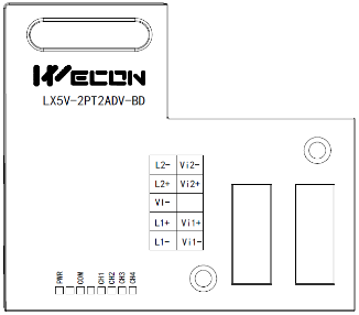
Terminal distribution:
IN_2PT part 2-wire/3-wire PT100 thermal resistance | IN_2ADV part Voltage output range: -10Vto10V | ||
| L2- | Channel 2 sensor Signal input negative | Vi2- | Channel 2 Voltage input negative |
| L2+ | Channel 2 sensor signal input positive | Vi2+ | Channel 2 Channel 1 voltage input positive |
| VI- | Sensor common pole | NC | |
| L1+ | Channel 1 sensor signal input positive | Vi1+ | Channel 1 Channel 1 voltage input positive |
| L1- | Channel 1 sensor Signal input negative | Vi1- | Channel 1 Voltage input negative |
LED lamp function description:
| Indicator lamp | Description |
| PWR | ON when power-on (when the program is running, it will be ON). |
| COM | It flashes when communicating with PLC normally, and it is OFF when timeout. |
| CH1 | Channel 1 lamp: Always on in range; Flashing outside the range of -100℃to600℃; Off when the channel is closed. |
| CH2 | Channel 2 lamp: Always on in range; Flashing outside the range of -100℃to600℃; Off when the channel is closed. |
| CH3 | Channel 3 lamp: Always on in range; flashing outside the range of (-10V to 10V); Off when the channel is closed. |
| CH4 | Channel 4 lamp: Always on in range; flashing outside the range of (-10V to 10V); Off when the channel is closed. |
3. Specification
1. General specification: Same as PLC main unit. (Please refer to the accompanying manual of the PLC main unit.)
2. Power supply specification: The power supply is provided internally by PLC.
3. Performance specifications:
| Project | Description | |
| Power supply | 5VDC±10%, 70mA (The power supply is provided internally by host) | |
| PT part | ||
| Analog input signal | Platinum thermal resistance PT100 sensor (100Ω), 3-wire, 2-channel input (CH1, CH2) | |
| Sensor current | 1mA sensor: 100 Ω (PT100) | |
| Compensation range | -100 ℃ to 600 ℃ (recommended range) | Over range display: 32767 |
| Digital output | -1000 to 6000 (unit 0.1 ℃) 12-bit conversion to 11 data bits + 1 sign bit | |
| Measurement accuracy | 0.2℃ to 0.3℃ | |
| Total accuracy | Full range ±0.5% (compensation range) | |
| Conversion speed | 2 channels 50ms | |
| Conversion features | 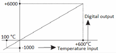 | |
| ADV section | ||
| Analog input range | DC-10V to 10V (input resistor 160KΩ). Note: If the input voltage exceeds ± 15V, it will be damaged. | |
| Rated range | (-10V to10V: -2000 to 2000) | |
| Maximum display range | -2048 to 2048 | |
| Resolution | 5mV [10V default range 1/2000] | |
| Comprehensive precision | ±0.5% of full scale | |
| A/D conversion time | 1 scan cycle (A/D conversion after ladder diagram END instruction is executed, and BD channel mapping value is updated) | |
| Input features | 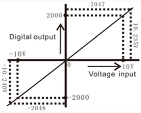 | |
| Insulation | There is no insulation between the channels of the module | |
4. Wiring
Wiring instructions:
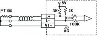
1. 2-wire PT100: When using channel 1, L1- and VI- are shorted with wires, and the two leads of the sensor are connected to L1+ and LI- respectively. Similarly, when using channel 2, L2- and VI- are shorted with wires, and the two leads of the sensor are connected to L2+ and L2- respectively.
2. 3-wire PT100: When using channel 1, two leads of the same color are connected to L1- and VI- respectively, and the other lead of different color is connected to L1+. Channel 2 is connected in the same way.
✎Note:
1. Cut off the power before installing, removing or wiring the BD module to avoid electric shock or product damage.
2. Do not place signal cables near high voltage power cables or in the same trunk line. Otherwise, it may be disturbed or surged. Keep a safe distance between signal cable and power cable, at least 100mm.
3. Ground the shielding of shielded wire or shielded cable. But the ground point and high voltage line cannot be the same.
4. Do not connect cables of impermissible size to avoid poor contact or product damage.
5. Fix the cable so that no force directly acts on the terminal line or cable connection area.
6. The tightening torque of terminal is 0.5Nm to 0.6N.m. Please tighten it to prevent malfunction.
7. Do not use empty terminals.
4.1 Applicable cables
1. AWG25-16 is used for connection with output device.
2. Maximum terminal tightening torque is 0.5N.m to 0.6N.m.
3. Using different types of cables may cause poor contact with terminals. Please use pressfit terminals for good contact.
Line number and cross-sectional area
| Line number | Cross-sectional area (mm2) | 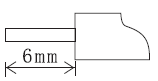 End processing End processing |
| AWG26 | 0.1288 | Stranded cable: Strip off the sheath, rub the core wire, and then connect the cable. Single-core cable: Strip off the sheath and connect the cable. |
| ... | ... | |
| AWG16 | 1.309 |
4.2 I/O Mode
Thermal resistance PT100 input mode:
Voltage input mode:
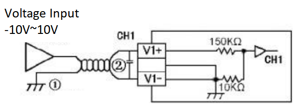
1. Analog input is received through twisted pair shielded cable. Cables should be kept away from power lines or other wires that may cause electrical interference.
2. If there is voltage fluctuation in the input or electrical interference in the external wiring, a smoothing capacitor can be connected (0.1uF to 0.47uF, 25V).
5. Description of PLC device
1. When connected to LX3 series PLC, please refer to LX3 series BD module manual.
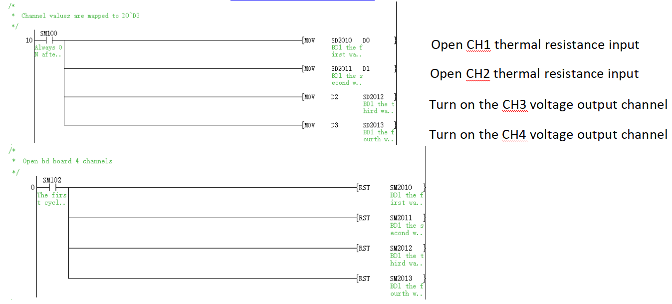
2. When connected to LX5 series PLC, if the firmware version of PLC is lower than 2.051 (excluding 2.051), or BD module is not configured by host computer, it can be controlled by the following system devices:
Device allocation:
| PLC model | BD Model | Device | Description | Device | Description | |
| LX5V | 2PT2ADV | SM2010 | CH1 thermal resistance input channel open flag | OFF: Open ON: Close | SD2010 | The temperature of CH1 at 0.1°C (-100℃ to 600℃: -1000 to 6000) |
| SM2011 | CH2 thermal resistance input channel open flag | SD2011 | The temperature of CH2 at 0.1°C (-100℃ to 600℃: -1000 to 6000) | |||
| SM2012 | CH3 voltage input channel open flag | SD2012 | CH3 digital value (-10V to10V: -2000 to 2000) | |||
| SM2013 | CH4 voltage input channel open flag | SD2013 | CH4 digital value (-10V to10V: -2000 to 2000) | |||
3. User can select device through I/O mapping to use the configuration function of new BD module. For details, please refer to "6.1 Parameter configuration".
6. Instructions
6.1 Parameter configuration
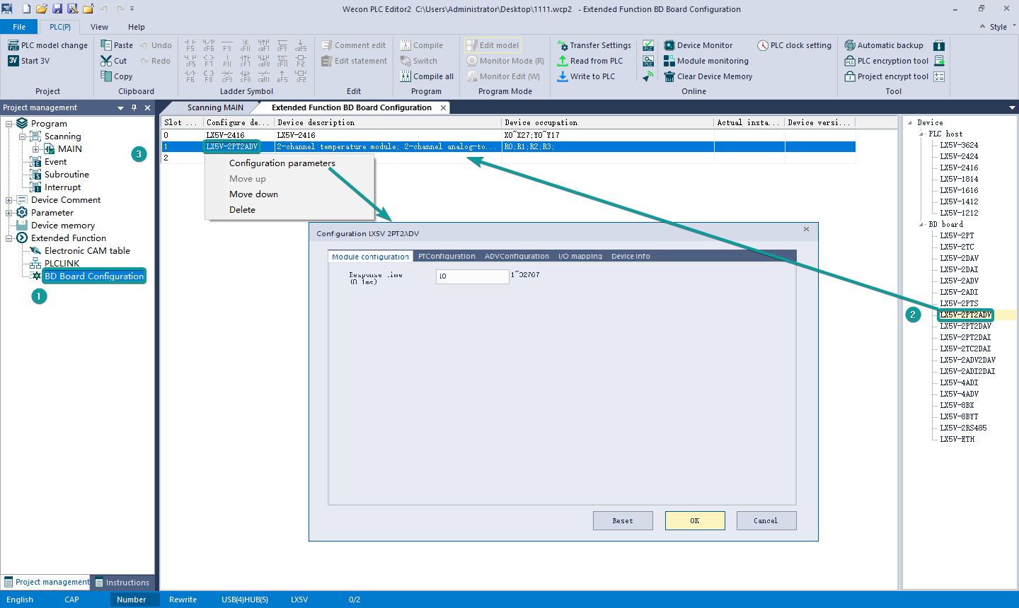
① Open the host computer software and create a new project, in “Project Manager” → “Extended Function” , double-click "BD Module Configuration" Noteto enter “BD settings” interface;
② Configure the currently connected PLC (take the LX5V-2416 model as an example) and BD module model on the BD module configuration interface: Select “LX5V-2PT2ADV" in the device bar on the right side of the BD module configuration interface and double-click to add it to the corresponding slot position of PLC (slot number 1 or 2, the software will select slot 1 by default, and right-click to move down to slot 2);
③ After adding the BD module to the slot, double-click or right-click to select configuration parameters to enter LX5V-2PT2ADV-BD configuration parameters interface, as shown in the following figure. Configure related parameters on this interface.
✎Note: This function is only supported in the following versions of host computer, slave computer and BD module:
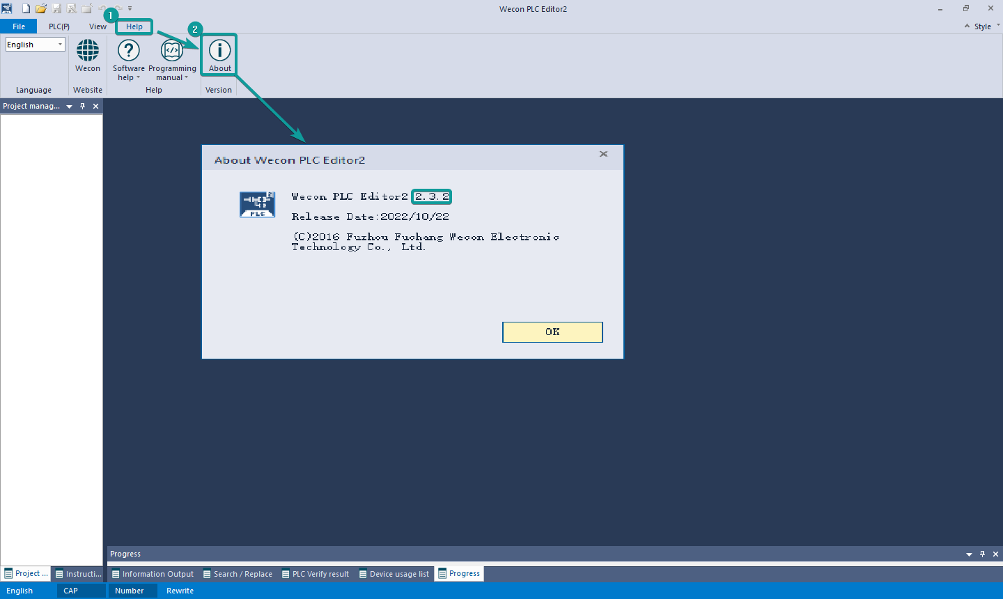
(1) Supported host computer software versions: Wecon PLC Editor2 2.1.204 and above, as shown in the following figure:
(2) Supported PLC firmware: 2.051 and above, as shown in the following figure:
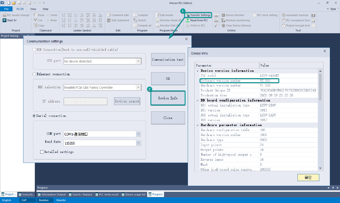
(3) Supported BD module version number: 1013 and above, as shown in the following figure:

The parameter configuration interface is as below:
1. Module setting: Set response time (The response time is the interval time between PLC acquisition of BD module data. Range: 0.1ms to 3276.7ms).

2. PT configuration:
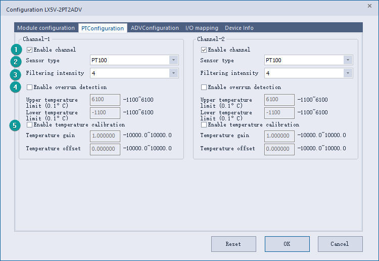
1. Check enable channel to set whether to enable the current BD module channel.
2. Sensor type: PT100 by default.
3. Setting the filtering intensity can reduce the jitter of BD channel value. The default configuration of filter intensity is 4. Level 0 is the lowest and level 9 is the highest. The filter intensity can be adjusted according to actual use.
4. Check enable overrun detection to judge that when the upper and lower limits of temperature exceed the current setting temperature, the host computer will prompt an error.
5. Check enable calibration, you could calculate the gain offset according to the following formula to convert the corresponding channel value:
Channel value = actual temperature value × gain value + offset value
When the channel value deviates from the actual temperature value, the channel can be calibrated by setting the gain offset, for example:
- The input temperature of control channel is 0℃, the value of acquisition channel is 30 (unit: 0.1℃), and the actual channel value should be 0 (unit: 0.1℃).
- The input temperature of control channel is 500℃, the value of acquisition channel is 5200 (unit: 0.1℃), and the actual channel value should be 5000 (unit: 0.1℃).
Suppose the gain is a, and the offset is b, then 
Solve and get
 The calibration can be completed by setting the corresponding gain offset to the current channel.
✎Note: Using gain and offset calibration can only reduce the linear error. Since the PT100 resistance and temperature curve are nonlinear, there is still a certain error in partial temperature after the calibration is successful.
3. ADV configuration:
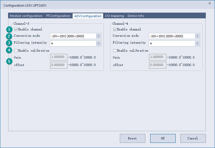
1. Check enable channel to set whether to enable the current BD module channel.
2. The conversion mode is set to ADV conversion mode by default. The measurement range is -10V to 10V (-2000 to 2000).
3. Setting the filtering intensity can reduce the jitter of BD channel value. The default configuration of filter intensity is 4. Level 0 is the lowest and level 9 is the highest. The filter intensity can be adjusted according to actual use.
4. Check enable calibration, you could calculate the gain offset according to the following formula to convert the corresponding channel value:
Channel value = digital value * gain value + offset value
5. When the channel value deviates, you could also set the gain offset to calibrate the channel. For example:
- When the channel input analog is 10V, the digital quantity of BD module acquisition channel value is 1970, and the actual digital value should be 2000.
- When the channel input analog quantity is 0V, the digital quantity of BD module acquisition channel value is 30, and the actual digital value should be 0.
Suppose the gain is a, and the offset is b, then ,
,
Solve and get The calibration can be completed by setting the corresponding gain offset to the current channel.
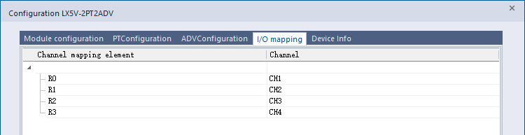
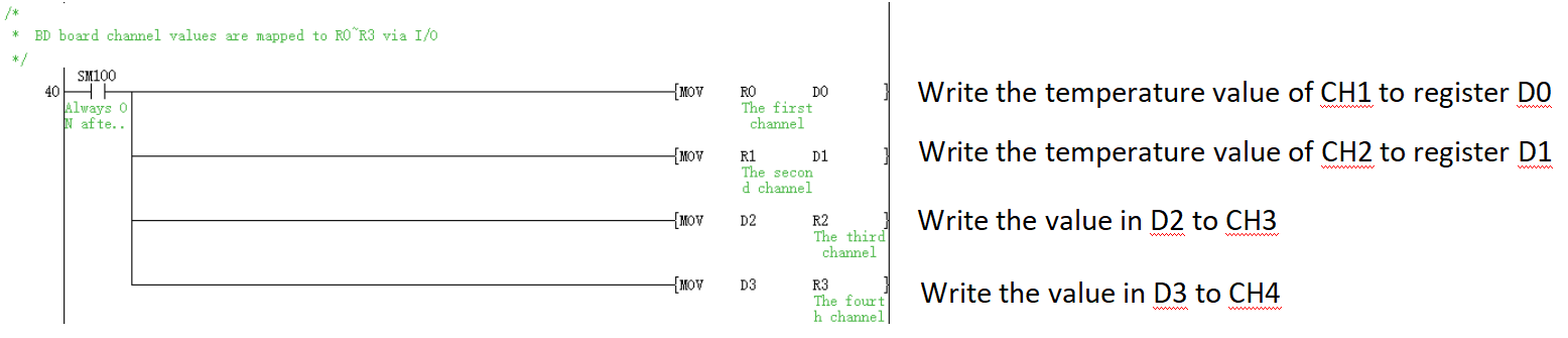
4. Set I/O mapping. The channels are mapped to R device according to the current number of BD module channels by default. As shown in the following figure, BD module CH1 to CH4 is mapped to device R0 to R3.
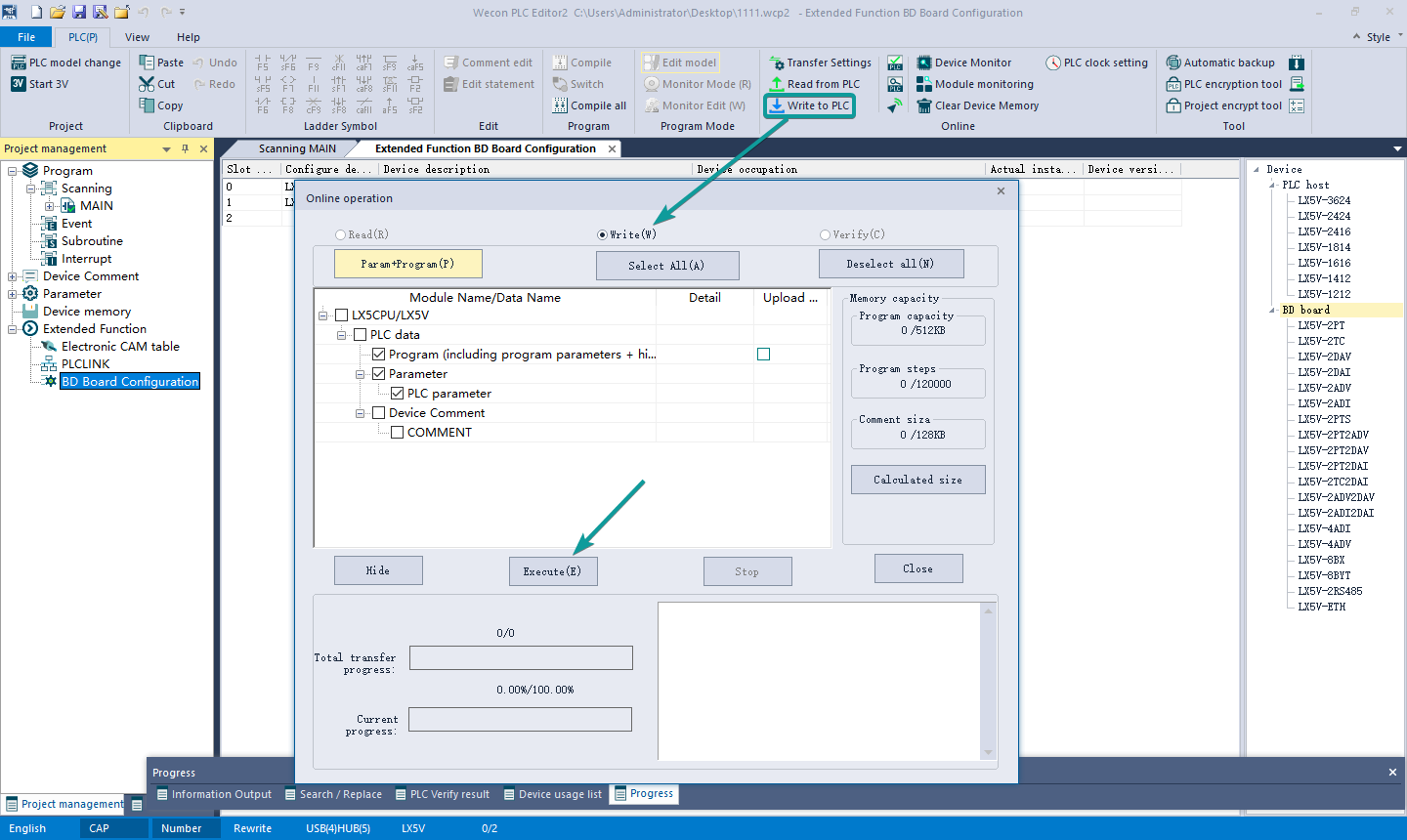
5. After the above configuration is completed, check the program, download the configuration to PLC, and STOP→RUN configuration takes effect.
6.2 Ladder Diagram
1. Programming example that does not use the host computer software "BD module configuration" function. For device allocation, please refer to "5 PLC device description".
2. Programming example using " BD module configuration" function of host computer software:
6.3 BD monitoring interface and buffer memory
Open the module monitoring interface, select BD module, select LX5V-2PT2ADV from the list of BD modules on the right to monitor it online, and check the current BD module communication status and error information in time.
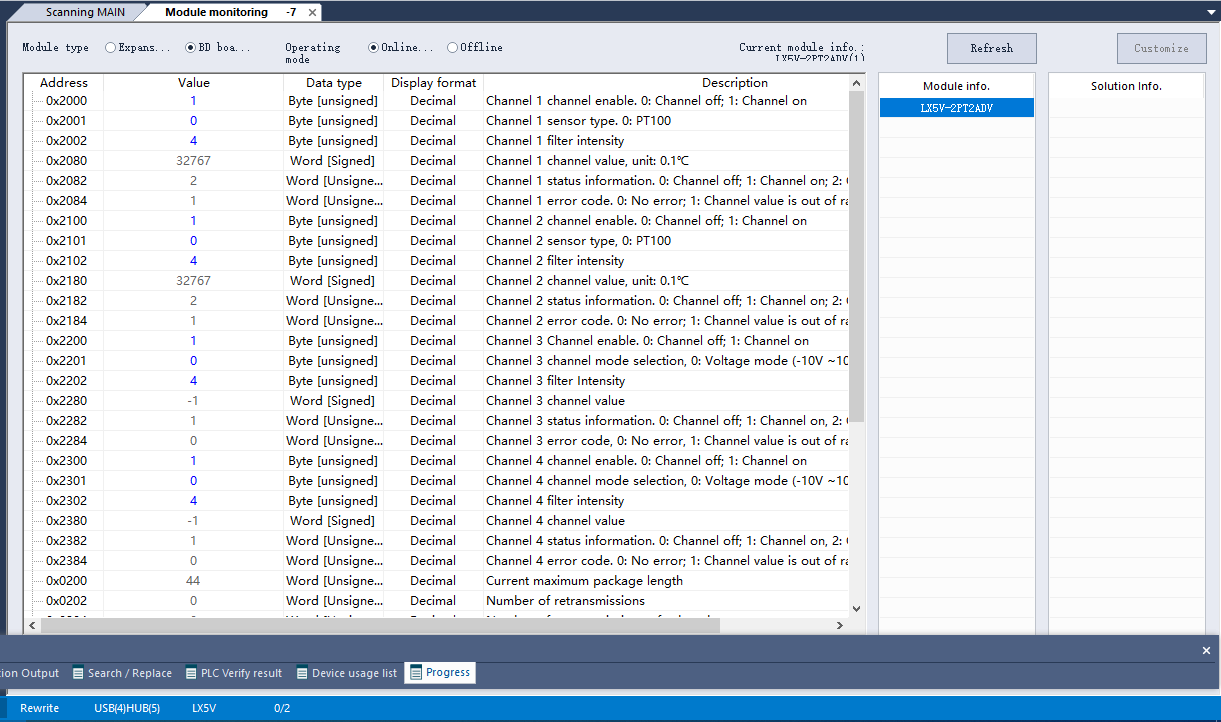
① PT buffer memory (BFM): used for BD module status monitoring.
BFM address | Power-off hold | Read/write | Memory name | Default | Range | Description |
| 0x2000 | × | R/W | Channel 1 channel enable | 1 | 0 to 1 | 0: Channel closed 1: Channel open |
| 0x2001 | × | R/W | Channel 1 sensor type | 0 | 0 | 0: PT100 |
| 0x2002 | × | R/W | Channel 1 filter intensity | 4 | 0 to 9 | 0: Minimum filter strength; 9: Maximum filter strength |
| 0x2080 | × | R | Channel 1 channel value | 32767 | -32768 to 32767 | Unit: 0.1℃ |
| 0x2082 | × | R | Channel 1 status information | 1 | 0 to 2 | 0: Channel closed 1: Channel opened 2: Channel value exceeds the range |
| 0x2084 | × | R | Channel 1 error code | 0 | 0 to 1 | 0: No error; 1: Channel value exceeds the range |
| 0x2100 | × | R/W | Channel 2 channel enable | 1 | 0 to 1 | 0: Channel closed 1: Channel open |
| 0x2101 | × | R/W | Channel 2 sensor type | 0 | 0 | 0: PT100 |
| 0x2102 | × | R/W | Channel 2 filter intensity | 4 | 0 to 9 | 0: Minimum filter strength; 9: Maximum filter strength |
| 0x2180 | × | R | Channel 2 channel value | 32767 | -32768 to 32767 | Unit: 0.1℃ |
| 0x2182 | × | R | Channel 2 status information | 1 | 0 to 2 | 0: Channel closed 1: Channel opened 2: Channel value exceeds the range |
| 0x2184 | × | R | Channel 2 error code | 0 | 0 to 1 | 0: No error; 1: Channel value exceeds the range |
② ADV buffer memory (BFM): used for BD module status monitoring.
BFM address | Power off hold | Read-write Function | Memory name | Default | Range | Description |
| 0x2200 | × | R/W | Channel 3 channel enable | 1 | 0 to 1 | 0: Channel closed 1: Channel open |
| 0x2201 | × | R/W | Channel 3 channel mode selection | 0 | 0 | 0: Voltage mode (-10V to 10V) |
| 0x2202 | × | R/W | Channel 3 filter intensity | 4 | 0 to 9 | 0: Minimum filter strength; 9: Maximum filter strength |
| 0x2280 | × | R | Channel 3 channel value | 0 | -2000 to 2000 | |
| 0x2282 | × | R | Channel 3 status information | 0 | 0 to 2 | 0: Channel closed 1: Channel opened 2: Channel value exceeds the range |
| 0x2284 | × | R | Channel 3 error code | 0 | 0 to 1 | 0: No error; 1: Channel value exceeds the range |
| 0x2300 | × | R/W | Channel 4 channel enable | 1 | 0 to 1 | 0: Channel closed 1: Channel open |
| 0x2301 | × | R/W | Channel 4 channel mode selection | 0 | 0 | 0: Voltage mode (-10V to 10V) |
| 0x2302 | × | R/W | Channel 4 filter intensity | 4 | 0 to 9 | 0: Minimum filter strength; 9: Maximum filter strength |
| 0x2380 | × | R | Channel 4 channel value | 0 | -2000 to 2000 | |
| 0x2382 | × | R | Channel 4 status information | 0 | 0 to 2 | 0: Channel closed 1: Channel opened 2: Channel value exceeds the range |
| 0x2384 | × | R | Channel 4 error code | 0 | 0 to 1 | 0: No error; 1: Channel value exceeds the range |
③ Universal buffer memory (BFM): used to diagnose the communication status of the currently connected BD module.
BFM address | Power-off hold | Read-write Function | Memory name | Default | Range | Description |
| 0x200 | × | R | Current maximum package length | 0 | 0 to0xFFFF | The maximum length of the currently sent package |
| 0x202 | × | R | Number of retransmissions | 0 | 0 to0xFFFF | Number of retransmissions |
| 0x204 | × | R | Number of retransmissions of subpackages | 0 | 0 to0xFFFF | Number of retransmissions of subpackages |
| 0x206 | × | R | Received times of sync frame | 0 | 0 to0xFFFF | Received times of sync frame |
| 0x208 | × | R | Sent times of sync frame | 0 | 0 to0xFFFF | Sent times of sync frame |
| 0x20A | × | R | Control the number of transmissions | 0 | 0 to0xFFFF | Control the number of transmissions |
| 0x20C | × | R | Control the number of receptions | 0 | 0 to0xFFFF | Control the number of receptions |
| 0x20E | × | R | Number of subscriptions sent | 0 | 0 to0xFFFF | Number of subscriptions sent |
| 0x210 | × | R | Number of subscriptions received | 0 | 0 to0xFFFF | Number of subscriptions received |
| 0x212 | √ | R/W | Latest error code | 0 | Only 0 can be written. | Protocol internal error code, write 0 to clear |
| 0x214 | × | R | Number of bytes sent | 0 | 0 to 0xFFFFFFFF | Number of bytes sent |
| 0x218 | × | R | Number of valid bytes sent | 0 | 0 to 0xFFFFFFFF | Number of valid bytes sent |
| 0x21C | × | R | Number of bytes received | 0 | 0 to 0xFFFFFFFF | Number of bytes received |
| 0x220 | × | R | Number of valid bytes received | 0 | 0 to 0xFFFFFFFF | Number of valid bytes received |
| 0x224 | × | R | Communication time (unit s) | 0 | 0 to 0xFFFFFFFF | Normal communication time since the BD module is powered on |