

LX6V EtherCAT Coupler
Overview
Product Overview
LX6V-EM□-ECAT communication modules support EtherCAT communication, equipped with auto scanning function, and adapt to Wecon and third-party EtherCAT master station device.
Main features:
- Compact structure and convenient installation;
- Response at microseconds of high-speed bus;
- The maximum number of expansion modules is 32, and the total power of modules≤48W;
Warranty statement
Normally, if the product fails or is damaged, our company provides maintenance service within the warranty period (see the order form for product warranty period details). After the warranty period, repair fees will be charged.
During the warranty period, if the product is damaged due to the following conditions, repair fees will be charged.
- Product damage caused by not operate the product according to the regulations in the manual.
- Product damage caused by fire, flood, and abnormal voltage.
- Product damage caused by abnormal functions.
- Product damage caused by exceeding the specified scope of use of the product.
- Secondary damage caused by force majeure (natural disaster, earthquake, lightning).
Responsibility statement
The contents of the manual have been carefully checked, but there is no guarantee that it is completely correct. We will regularly check the content of the manual and make corrections in subsequent versions. Valuable opinions are welcome. The contents described in the manual are subject to change without notice.
The relevant service fees shall be calculated according to the unified standards of the manufacturers. If there is a contract, the principle of contract priority shall be used. Please refer to Warranty Card for detailed warranty instructions.
Safety precautions
Please read this instruction manual and other related manuals carefully before installing, operating and maintaining the 6V-EM□-ECAT coupler to ensure correct use.
In this manual, safety precautions are divided into two categories: “WARNING" and "CAUTION".
 Before installing, operating, and maintaining the product, please be sure to read the instruction manual and other relevant manuals carefully to ensure correct use.
 Failure to operate according to the instructions in the manual may lead to improper installation, use and storage of the equipment, which may cause personal injury or even death, and cause property damage.
Installation precautions
To ensure safety system operation, please configure emergency braking circuit, positive inversion circuit or other protection circuit for PLC, which can prevent the damage to PLC or other devices.
- It is imperative to configure the relevant safety circuits externally to the programmable controller.
- All outputs are turned off, as an error be detected by PLC CPU during self-diagnosis, such as a watch dog timer error. When error that cannot be detected, internal protection circuit may be disabled.
- When relay and transistor are damaged, the output state of transistor in the PLC can’t be controlled. To ensure safe operation of the machine, please design external protection circuits and mechanisms for key output signals.
Start-up and maintenance precautions
Danger
- Do not touch the terminal when power-on, otherwise it may cause electric shock and misoperation.
- Please remove and clean the terminal after the power is off. Otherwise, it may cause electric shock when power-on.
- Please read the manual carefully and confirm the safety before performing program changes, forced output, RUN, STOP and other operations during machine running.
- Mistakes in operation will damage the machine and cause accidents.
Warning
- Please do not decompose and transform, otherwise it will cause failure, malfunction and fire.
- For maintenance matters, please contact FUJIAN FUCAN Wecon Electronic Technology Co., Ltd.
- Please load and unload the extension cable and other connecting cable after the power is turned off, otherwise it will cause failure and malfunction.
Maintenance and repair
- Whether the temperature inside the machine has risen abnormally due to other heating elements or direct sunlight.
- Whether there is dust or conductive dust intrusion into the machine.
- Whether there are loose wiring and terminals and other abnormalities.
Product information
Naming
| LX6V | EMB | ECAT |
|---|---|---|
| Series | Module type EMB: Support up to 16 expansion modules EMC: Support up to 32 expansion modules Note: Module total power≤48W | Communication type ECAT: EtherCAT |
Module support list
| Coupler | Supported module types | Module type | Coupler Version Version |
|---|---|---|---|
LX6V-EMB-ECAT LX6V-EMC-ECAT | Digital I/O module | LX6V-0808EXYT | V1.045 and above |
| LX6V-16EX | |||
| LX6V-16EYT | |||
| LX6V-16EYP | V2.013 and above | ||
| LX6V-1616EXYT | |||
| LX6V-1616EXYP | |||
| LX6V-32EX | |||
| LX6V-32EYT | |||
| LX6V-16EYP-3A | V2.106 and above | ||
| Pulse module | LX6V-8HC | V2.013 and above | |
| Analog I/O module | LX6V-4AD | V1.045 and above | |
| LX6V-4DA | |||
| Temperature module | LX6V-4PT | V2.106 and above | |
| LX6V-4TC |
Installation size
Appearance and size
| Series number | Interface name | Function definition | |||
|---|---|---|---|---|---|
| 1 | Signal indicator | PWR | Power indicator | Off | No power supply |
| On | Power on | ||||
| RUN | Running indicator | Off | ECT module is in INIT status | ||
Blink (White)* | ECT module is in Pre Op status | ||||
Single flash (White)* | ECT module is in Safe-Op status | ||||
Normally on (White) | ECT module is in Operational status | ||||
| ERR | Communication fault indicator | Off | EtherCAT communication is in normal status. | ||
| Blink (Red)* | EtherCAT communication receives status transition instructions that cannot be executed. | ||||
| Single flash (Red)* | Network disconnection, ECT module synchronization error | ||||
| On (Red) | Watchdog error occurred in EtherCAT communication | ||||
| 2 | USB Communication Interface (Type-C) | Used for single board software upgrade | |||
| 3 | EtherCAT interface | IN: EtherCAT input port | |||
| OUT: EtherCAT output port | |||||
| 4 | 24V power input interface | Module power input terminal | |||
| 5 | Expansion module interface | Connect LX6V series expansion module | |||
| 6 | Mounting hole | 2 places, φ4.5 | |||
| 7 | DIN rail fastener | ||||
*Blink: On for 200ms, off for 200ms
*Single flash: On for 200ms, off for 1s
Electrical installation
Communication wiring
- Cable recommendation
EtherCAT bus communication uses STP/FTP cable for network data transmission, without short circuit, dislocation and bad contact.
The length of the cable between the devices cannot exceed 100 meters. Exceeding 100 meters will cause signal attenuation and affect normal communication.
It is recommended to use the following specifications of data cables:
| Item | Specifications |
|---|---|
| Type of cable | Elastic crossover cable, Category 5E (cat 5e) cable and above |
| Traverse cross section | AWG26 |
| traverse type | Twisted pair |
| Line pairs | 4 pairs |
- Wiring instructions
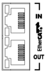
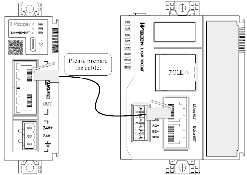
Wiring is carried out according to the radium engraving of the shell, where the IN interface is EtherCAT input port, which is used to connect the EtherCAT master station; The OUT interface is an EtherCAT output port, which is used to connect the later EtherCAT slave station.
Power terminal wiring
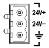
Connect the positive and negative electrodes of the 24V power supply according to the shell marks; The cross-sectional area of the grounding wire is not less than 2mm2, and the grounding resistance is less than 100Ω.
Specification parameters
Specification parameter
| Specification parameter | ||
|---|---|---|
| Item | LX6V-EMB-ECAT | LX6V-EMC-ECAT |
| Rated input voltage | DV 24V±10%, 100mA (without expansion module) | |
| Communication interface | RJ45×2, EtherCAT communication protocol with 100Mbps performance; EtherCAT IN: EtherCAT input port; EtherCAT OUT: EtherCAT output port. | |
| Transmission distance | Length of communication line between two nodes≤100m | |
| Transmission medium | Category 5E (cat 5e) cable or above | |
| Single AP process data | Maximum input and output 1024 bytes | |
| Synchronous | Minimum 125us | |
| Allowable instantaneous power-off time | 10ms | |
| Impulse current | ≤45A (loaded with maximum module) | |
| Power protection | Anti-reverse connection protection, overcurrent protection and surge absorption | |
| Maximum number of expansion modules | 16 | 32 |
| Firmware upgrade | Support | |
Environmental specifications
| Item | Specification parameter |
|---|---|
| Usage environment | No corrosive, combustible gas, no large amount of conductive dust(dust) |
| Environment temperature | Operating temperature: -20℃ to 55℃ Storage temperature: -40℃ to 70℃ |
| Environment humidity | Working humidity: 10% to 90%RH (No condensation) Storage humidity: ≤90%RH (No condensation) |
| Altitude | 0-2000m |
| Installation | Installed on DIN46277 (Width: 35mm) rail by fastener |
| Overall size | 91*34*94.8mm |
LX6V-EM□-ECAT Module Instructions for Use
This module is compatible with Wecon LX6V, LX6S and LX6C PLC. The following is the usage for the different models.
Use on LX6V/LX6S hosts
(1) Add EtherCAT device
① Right-click EtherCAT, click [New]->[Import], importing ESI file of the device;
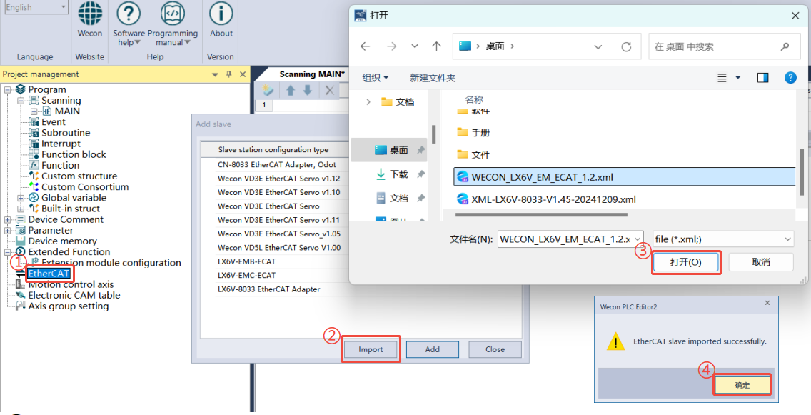
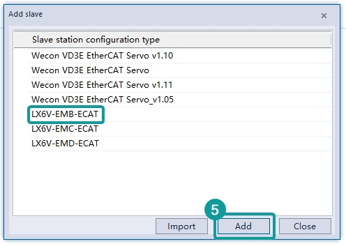
② Select the coupler according to the model and position of the current connected module;
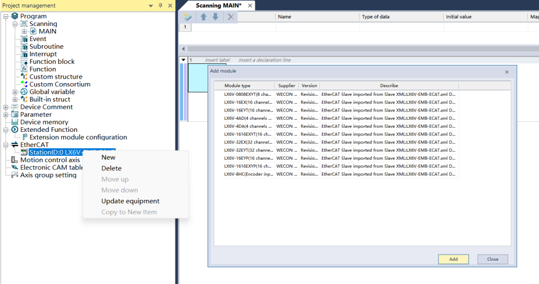
③ Right-click the current coupler to add the expansion module mounted by the current coupler;
④ Configure modules sequentially X-point filtering time and I/O map. Click OK to save configuration;
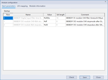
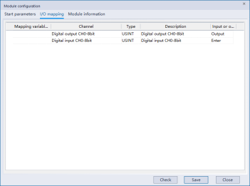
Filtering time (Unit: 0.1ms): The default configuration filter time here is 1ms, and the set range: 0-64ms. I/O mapping: The X and Y points of the modules are sequentially mapped to X10-X17 and Y10-17 of the PLC.
⑤ Click on the interface in turn PLC Download, check the extension function, click Execute, and download the extension module configuration to PLC.
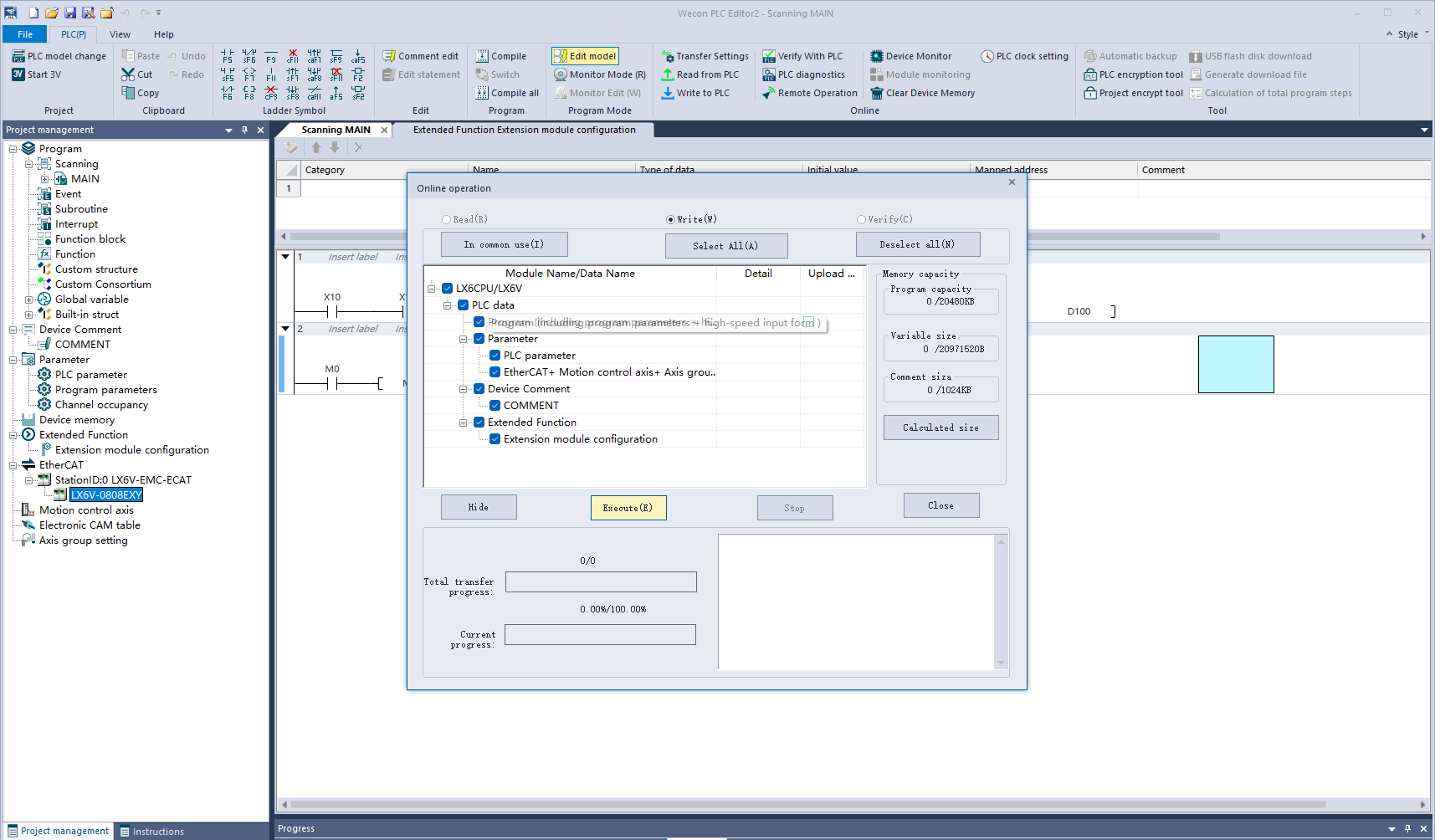
Use on an LX6C host
(1) Install Device Description File
When using it for the first time, you need to install the slave device description file (the device description file can be downloaded from the official website, name: WECON_LX6V_EM_ECAT_1.0.xml).
Operation steps:
[Tools]->[Device repository]->[Installation]
Select Coupler Device Description File to complete installation.
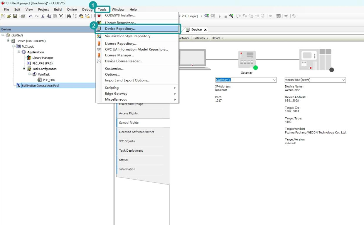
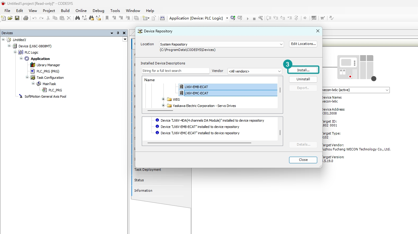
(2) Add EtherCAT master device
[Equipment]->[Add device]->[Fieldbus]->[Ethecat Master or Ethecat Master SoftMotion]
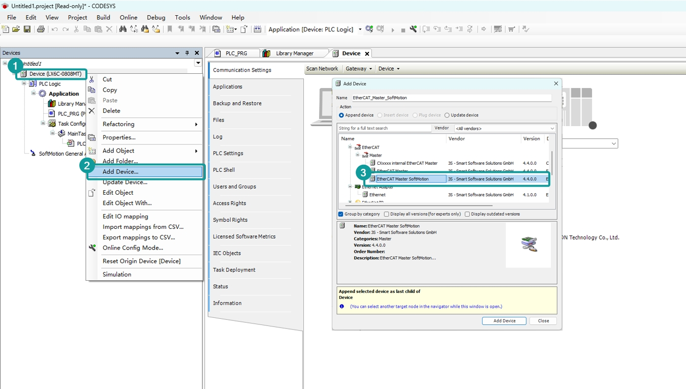
(3)Add coupler and external expansion module
① Add manually
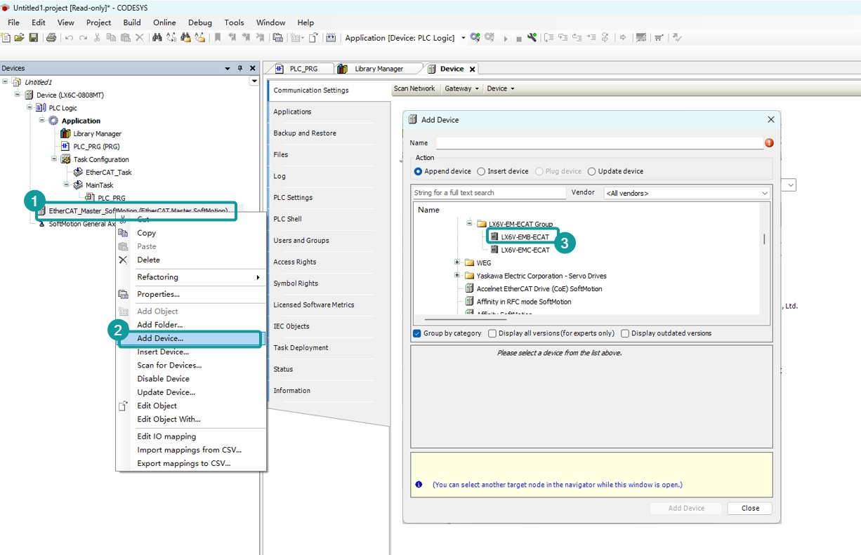
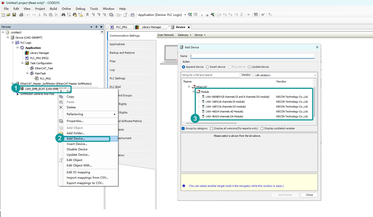
②Scanning mode
Right-click to scan
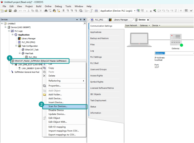
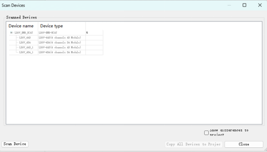
③Copy all the modules to project
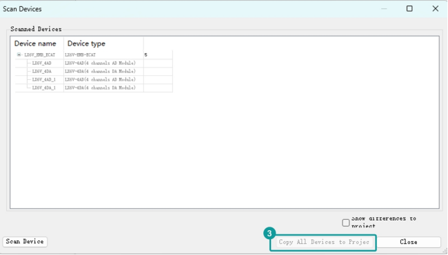
④Configure startup parameters and IO mapping
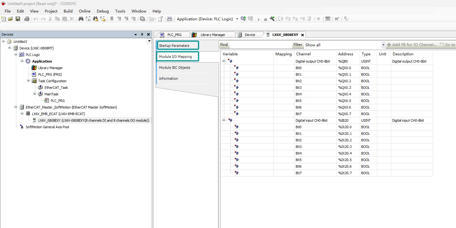
No errors are reported when compiling, just download the program and run it.
LX6V-EM□-ECAT connect with other expansion module
Digital IO module
(1) Add EtherCAT device
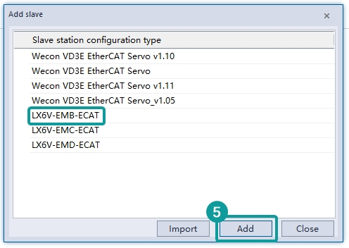
Right-click EtherCAT and click [New]→[Import], import ESI file of device.
Import completed. As the following figure, select coupler according to the current host module model and position. (Take LX6V-EMB-ECAT as an example)
(2) Configure module
Right-click the added coupler. Add the new expansion module loaded on the current coupler.
(3) Configure module parameter
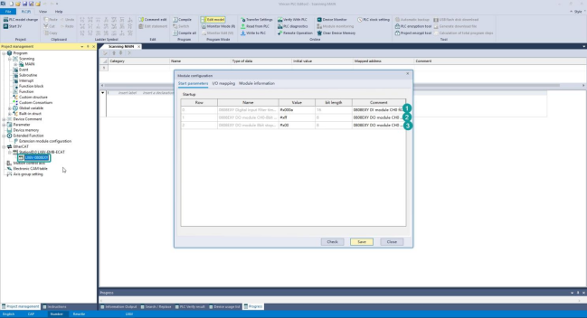
DA configuration
①0808EXY Digital input Filter time 8bit: used to set 0808EXY input point filter time.
Default 1ms, unit: 0.1 ms
Configurable range: 0ms-64ms
②0808EXY DO module CH0-8bit stopmode after EtherCAT lost link: used to set 0808EXY output point stop mode when EtherCAT disconnected.
DO stop mode
0: Keep output after EtherCAT disconnected.
Non-0: Use stopvalue output after EtherCAT disconnected.
③0808EXY DO module 8bit stopvalue after EtherCAT lost link: used to set 0808 EXY output point DO output value after EtherCAT disconnected.
I/O mapping
IO module input and output point can be mapped to variable/device.
For example, the figure below maps the DO channel value to the lower 8 bits of the D0 device, and the DI channel maps to the lower 8 bits of the D1 device.
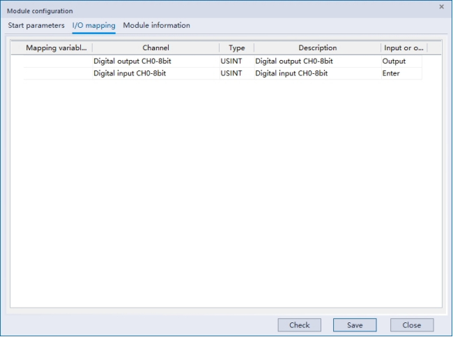
Click save to download to PLC.
4AD module
(1) Add EtherCAT device
Right-click EtherCAT and click [New]→[Import], import ESI file of device.
Import completed. As the following figure, select coupler according to the current host module model and position. (Take LX6V-EMB-ECAT as an example)
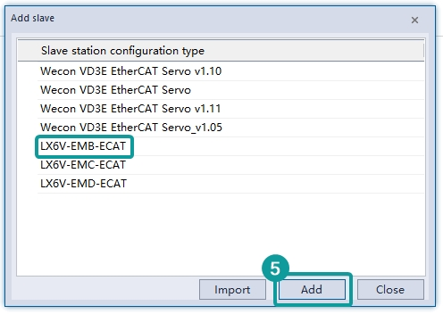
(2) Configure module
Right-click the added coupler. Add the new expansion module loaded on the current coupler.
(3) Configure module parameter
AD configuration
①4AD module Chx transform mode: used to set the current channel CHx (x∈[0,3]) change mode.
Support mode:
0: Not enable;
1: -10V-10V (-10000-10000)
2: 4mA-20mA (0-20000)
3: -20mA-20mA (-20000-20000)
② reverse: Reserve, not in use yet.
③ 4AD module CHx filter time: used to specify the current channel CHx (x∈[0,3]) filter time.
I/O mapping
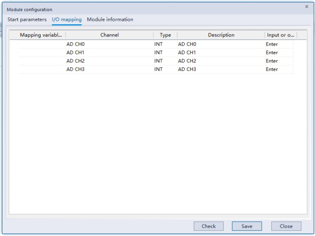
IO module input and output point can be mapped to variable/device.
For example, the figure below maps the DO channel value to the lower 8 bits of the D0 device, and the DI channel maps to the lower 8 bits of the D1 device.
Click “Save” and download to PLC.
4DA module
(1) Add EtherCAT device
Right-click EtherCAT and click [New]→[Import], import ESI file of device.
Import completed. As the following figure, select coupler according to the current host module model and position. (Take LX6V-EMB-ECAT as an example)
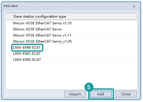
(2) Configure module
Right-click the added coupler. Add the new expansion module loaded on the current coupler.
(3) Configure module parameter
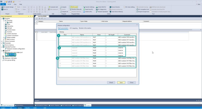
DA configuration
4DA module Chx transform mode: used to set the current channel CHx (x∈[0,3]) change mode.
Support mode:
0: Not enable;
1: -10V-10V (-10000-10000)
2: 4mA-20mA (0-20000)
3: -20mA-20mA (-20000-20000)
4DA module CHx stopmode: used to specify the current channel CHx (x∈[0,3]) stopmode
0: output clear
1: keep output
2:Output preset value
4DA module Chx stopvalue: used to specify the current channel CHx(x[0,3]) to set the digital as output preset value mode
When 4DA module CHx stopmode is set to 2, if PLC STOP or EtherCAT disconnected, module channel will output this parameter specified digital.
I/O mapping
Module CH0- CH3 map to variable/device the D0-D3 device.
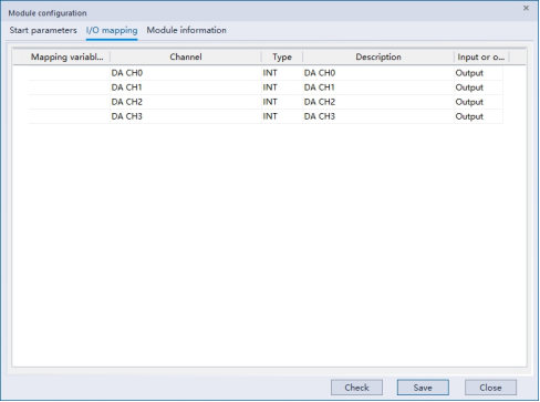
Click “Save” and download to PLC.
Object dictionary
| Model | Index | Sub-index | Name | Type | Range | Read and write support | Default value | Description |
|---|---|---|---|---|---|---|---|---|
| LX6V-EMB (D)-ECAT | 16#1000 | 16#00 | Device type | UINT32 | -- | R | -- | Coupler device model |
| 16#1001 | 16#00 | Error register | UINT16 | -- | R | -- | Error register, which holds error codes | |
| 16#1008 | 16#00 | Device name | STRING (15) | -- | R | -- | Device name | |
| 16#1009 | 16#00 | Hardware version | STRING (13) | -- | R | -- | Hardware version number | |
| 16#100A | 16#00 | Software version | STRING (13) | -- | R | -- | Software version number | |
| 16#1018 | 16#00 | Identity | UINT32 | -- | R | -- | Device Identifier | |
| 16#01 | Vendor ID | UINT32 | -- | R | -- | Manufacturer ID | ||
| 16#02 | Product Code | UINT32 | -- | R | -- | Product code | ||
| 16#03 | Revision number | UINT32 | -- | R | -- | Version code | ||
| 16#04 | Serial Number | UINT32 | -- | R | -- | SN | ||
| 16#F100 | 16#00 | local bus status | UINT32 | -- | R | -- | Local bus status | |
| 16#F120 | 16#00 | local bus information | UINT32 | -- | R | -- | Local module information | |
| 16#01 | local bus link count | UINT32 | -- | R | -- | Total local module connections | ||
| 16#02 | local bus communication total count | UINT32 | -- | R | -- | Total number of local module communications | ||
| 16#03 | local bus communication error count | UINT32 | -- | R | -- | Number of local module communication errors |
Error code
| Error code | Description | Action | Solution | Detect time |
|---|---|---|---|---|
| 7080 | Expansion module check error | Keep running | Check whether there is external interference the connection between expansion module and host | During instruction execution |
| 7081 | Expansion module communication reporting error | Keep running | Check whether there is external interference the connection between expansion module and host | During instruction execution |
| 7083 | Expansion module access error | Keep running | Check the connection between expansion module and host | During instruction execution |
| 7084 | Expansion module config quantity does not match the actual quantity | Keep running | Check whether the configuration is correct | During instruction execution |
| 7110 | Expansion module configuration error | Stop running | Check whether expansion module configuration is correct | During instruction execution |