04 Program Flow
Program Jump
CJ/Conditional Jump
When the jump instruction is ON, the program with the specified pointer number in the same program file is executed.
-[CJ (P) (P)]
Content, range and data type
| Parameter | Content | Range | Data type | Data type (label) |
|---|---|---|---|---|
| (P) | The pointer number of the jump target | P0 to P4095 | Device name | POINTER |
Device used
| instruction | Parameter | Devices | Offset modification | Pulse extension | other | |||||||||||||||||||||||
| X | Y | M | S | SM | T(bit) | C(bit) | LC(bit) | HSC(bit) | D.b | KnX | KnY | KnM | KnS | T | C | D | R | SD | LC | HSC | K | H | E | [D] | XXP | P | ||
| CJ | Parameter 1 | ● | ● | |||||||||||||||||||||||||
Features
- CJ(P)
When the execution instruction is ON, the program with the specified pointer number is executed.
When the execution instruction is OFF, execute the next program.

- Execute instructions.
- Each scan is executed.
- One scan is executed.
When the OUT instruction is jumped by the CJ(P) instruction, the scan time will be shorter.
When the CJ(P) instruction is used to jump backward, the scan time will be longer.
For the CJ(P) instruction, you can jump to a step smaller than the step number being executed. However, in order to avoid the time limit of the watchdog timer, a method of jumping out of the loop during this period should be considered.

• The device skipped by the CJ(P) instruction does not change.

• The label (P□) occupies 1 step.

The jump instruction can only specify the pointer number in the same program file.
When jumping to the pointer number within the jump range during jump operation, the program after the jump destination pointer number is executed.
The label procedure is shown below. When creating a loop program, move the cursor to the left of the bus bar of the ladder diagram, and enter the label (P) at the beginning of the loop block.

It is also possible to program the label at the position where the step number is less than the CJ instruction, but if the scan time becomes more than 200ms (default setting), a watchdog timer error will occur, which requires attention.

When the pointer number in the operand is the same and the label is one, the operation is as follows.
If the tag number is reused, it will become an error state.

SM100 is always ON during the operation of the CPU module, so the usage method shown below will jump unconditionally.

The pointer number P63 of LX3V represents the jump to the END instruction. The P63 pointer of LX5V no longer provides this function. If you need to use this function, please use the GOEND instruction.
Error code
No error message
Example
1) The situation to jump after OFF processing
After one operation cycle when X023 changes from OFF to ON, the CJ P7 instruction is valid.
With this method, the output between CJ P7 instruction and mark P7 can be turned off before jumping.

2) CJ instruction and action of contact coil
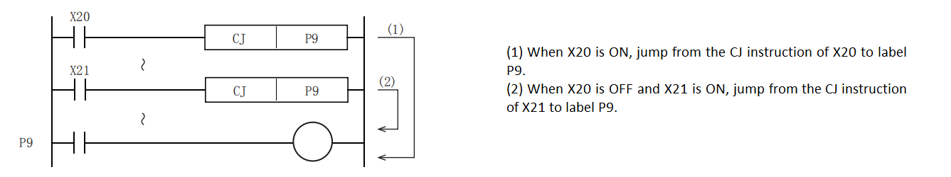
In the following program example, when X000 is ON, jump from the CJ instruction of the first loop to the mark P8. When X000 is OFF, no jump is performed, but the program is executed in order from step 1, and the CJ instruction in the 11th loop jumps to mark P9. The jumped instruction is not executed.
 Double-coil action of Y001 output:
When X000=OFF, it will act through X001.
When X000=ON, it will act through X012.
Even if the program is distinguished by conditional jump, if the same coil (Y000) is programmed twice or more within or outside the jump, it will be treated as normal double coil processing.
The action of the subroutine timer (T192 to T199):
After the coil is driven, the action continues even if it jumps, and the output contact also operates.
If using the high-speed counter (HSC0 to HSC7) operation
After the coil is driven, the action continues even if it jumps, and the output contact also operates.
In the above program, if each input changes during the jump, the action of each coil is shown in the following table.
| Content | Contact state before jump | Coil action in jump |
|---|---|---|
Y,M,S (Y1, M1, S1) | X1, X2, X3 OFF | Y1, M1, S1 OFF |
| X1, X2, X3 ON | Y1, M1, S1 ON | |
1ms, 10ms, 100ms timer (T0) | X4 OFF | Timer not working |
| X4 ON | Timer interrupt (continue after X0 OFF) | |
Program timer (T192) | X5 OFF, X6 OFF | Timer not working, but the timer is reset when X13 is ON |
| X5 OFF, X6 ON | Timing continues (contact action after X0 OFF) | |
Counter (C0) | X7 OFF, X10 OFF | Counting interrupt, but it is reset when X13 is ON |
| X7 OFF, X10 ON | Count interruption (continue after X0 OFF) | |
application instructions (MOV) | X11 OFF | Single-cycle application instructions are not executed in the jump Multi-cycle application instructions are partially executable (such as high-speed pulse instructions) |
| X11 ON |
3) The relationship between CJ instruction and MC to MCR jump
The relationship between the main control instruction and the jump instruction and the action content is as follows.
However, since the operation of ②, ④, and ⑤ will become complicated, please avoid using them.

Subroutine Jump
CALL/Subroutine Call
When the jump instruction is ON, the program with the specified pointer number in the same program file is executed.
-[CALL (P) (P)]
Content, range and data type
| Parameter | Content | Range | Data type | Data type (label) |
|---|---|---|---|---|
| (P) | Subroutine name | - | Pointer | POINTER |
Device used
| instruction | Parameter | Devices | Offset modification | Pulse extension | other | |||||||||||||||||||||||
| X | Y | M | S | SM | T(bit) | C(bit) | LC(bit) | HSC(bit) | D.b | KnX | KnY | KnM | KnS | T | C | D | R | SD | LC | HSC | K | H | E | [D] | XXP | Subroutine name | ||
| CALL | Parameter 1 | ● | ● | |||||||||||||||||||||||||
Parameter 1 can only use the subroutine name.
Features
When the CALL(P) instruction is executed, the subroutine of the pointer (P) will be executed. (P) can only be written with the name of the newly created subroutine, if the program name does not exist, the ladder diagram compilation fails.

CALL(P) instructions can be nested up to 32 levels.

Error code
| Error code | Content |
|---|---|
| 4102H | CALL(P) instruction exceeds 32 levels of nesting structure |
Example
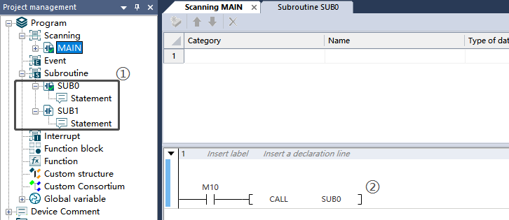
1) New subroutine
Project management→Subroutine→ Scan→Right click to create

2) Subroutine call


In the scan program, turn on M10 to call the subroutine SUB0, execute the ladder diagram in the subroutine SUB0, until the END instruction of the subroutine is executed, return to the scan program MAIN to execute LD M11.
3Z) Subroutine nesting

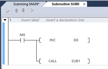

In the above figure, the subroutine SUB0 is called in the scan program, and the subroutine SUB1 is called in SUB0. So when the scan program M10 is turned on, after the CALL instruction is executed, the subroutine SUB0 will be executed first.And after the CALL instruction of SUB0 is executed, SUB1 will be executed first. After executing the END instruction of SUB1, return to SUB0 for execution. After executing the END instruction of SUB0, return to the scan program MAIN. The program has only 2 levels of nesting, and the number of nesting levels cannot be greater than 32.
Interrupt Disable, Interrupt Enable
DI and EI/Interrupt Prohibited and Allowed
The CPU module is usually interrupt disabled. This instruction can make the CPU module into the interrupt enabled state (EI instruction), and then become disabled again (DI instruction).
• DI: It is forbidden to interrupt program execution.
• EI: Release the interrupt prohibition state.
-[DI (s)]
-[EI]
Content, range and data type
| Parameter | Content | Range | Data type | Data type (label) |
|---|---|---|---|---|
| (P) | Subroutine name | - | Pointer | POINTER |
| instruction | Parameter | Devices | Offset modification | Pulse extension | |||||||||||||||||||||||
| X | Y | M | S | SM | T(bit) | C(bit) | LC(bit) | HSC(bit) | D.b | KnX | KnY | KnM | KnS | T | C | D | R | SD | LC | HSC | K | H | E | [D] | XXP | ||
| DI | Parameter 1 | ● | |||||||||||||||||||||||||
Features
- DI
• Even if the execution interrupt condition is triggered in the program, prohibit the interrupt program execution before executing the EI instruction.
• When the PLC is powered on or after STOP, it will become the state after DI instruction is executed, and the interrupt program cannot be executed.
• The DI instruction can choose whether to use parameters. When there is no parameter, it means that all interrupt programs are prohibited. With parameters, according to the value in parameter s1, interrupt programs with this priority and lower priority are prohibited.
• The priority of the interrupt ranges from 0 to 2. The smaller the value, the higher the response priority of the interrupt. That is, the interrupt with priority 0 is the fastest to be responded.
• If there is no EI instruction before the DI instruction, the DI instruction is invalid.
- EI
• Release the interrupt prohibition state when DI instruction is executed, and allow interrupt program to run.
• When the EI and DI instructions are not enabled, they all maintain the original enabled or forbidden interrupt program execution status. The currently disabled interrupt priority can be viewed in SD151.
| SD151 | Currently disabled interrupt priority | According to the interrupt prohibition instruction (DI instruction), the interrupt prohibition instruction (DI instruction) below the specified priority, and the interrupt enable instruction (EI instruction), the priority of the interrupt prohibition will be stored. 0: All priority interrupts are disabled (default); 1: Priority 1 and 2 interrupts are prohibited; 2: Priority 2 interrupt is prohibited; 3: All priority interrupts are allowed | R(read only) |
|---|
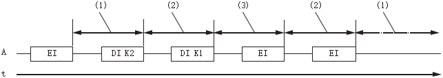
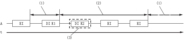
- DI, EI nested structure
 A: Sequence control program
(1) Interrupt allowable intervals of all priority levels;
(2) Interrupt forbidden zone below priority 2 (interrupt allowable zone above priority 1);
(3) Interrupt forbidden interval below priority 1 (interrupt allowable interval above priority 0);
(4) Interrupt prohibition zone below priority 2 (interrupt enable zone above priority 1);
(5) Interrupt allowable intervals of all priority levels;
(6) EI paired with [DI K1];
(7) EI paired with [DI K2].
• Interrupts (requests) that occur after the DI instruction are processed after the EI instruction is executed.
• When the DI instruction is executed multiple times and the priority of the argument is specified to be higher than the priority currently being prohibited, interrupts below the priority of the argument are disabled.
• When the DI instruction is executed multiple times and the priority of the argument is specified to be lower than the priority currently being disabled, the interrupt disable status will not be changed.
• The nesting of DI instructions can be up to 16 levels.
• The interrupt priority of the interrupt pointer can be set by the properties of the interrupt program. Refer to the description of the interrupt program for details.
• The interrupt prohibition interval when DI instruction and EI instruction are executed is as follows.
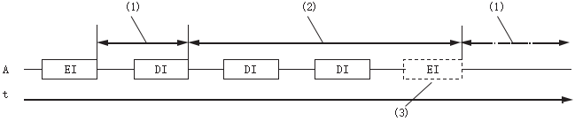
1) When the DI instruction is executed multiple times (when the interrupt with priority higher than the currently prohibited interrupt priority is prohibited and specified)
Scan execution type program
- Interrupt allowable intervals of all priority levels;
- Interrupt prohibition interval below priority 2 (interrupt allowable interval above priority 1);
- Interrupt prohibition section below priority 1 (interrupt enable section above priority 0).
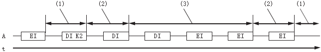
2) When the DI instruction is executed multiple times (when the interrupt priority is lower than the currently prohibited interrupt priority is prohibited and specified)
Scan execution type program
- Interrupt allowable intervals of all priority levels;
- Interrupt prohibited interval below priority 1 (interrupt allowable interval above priority 0);
- The interrupts below priority 1 are already in the disabled state, so the interrupt disable priority will not be changed.
3) When DI instruction is executed through interrupt program

A: Scan execution type program
B: interrupt program
- Interrupt allowable intervals of all priority levels;
- Interrupt prohibited interval below priority 3 (interrupt allowable interval above priority 1);
- Interrupt prohibition section below priority 2 (interrupt enable section above priority 0).
4) When only DI instructions without arguments are executed
A: Scan execution type program
- Interrupt allowable intervals of all priority levels;
- Interrupt prohibition interval below priority 1 (all interrupt prohibition intervals);
- Because the DI instruction with no argument is set to interrupt prohibition, by executing the EI instruction once, all priority interrupts are set to allow.
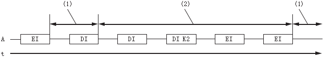
5) In the case of executing DI instructions with arguments and DI instructions without arguments (when executing in the order of DI instructions with arguments → DI instructions without arguments)
A: Scan execution type program
- Interrupt allowable intervals of all priority levels;
- Interrupt prohibition interval below priority 2 (interrupt allowable interval above priority 1);
- Interrupt prohibition section below priority 1 (all interrupt prohibition sections)
6) In the case of executing DI instructions with arguments and DI instructions without arguments (in the case of execution in the order of DI instructions with no arguments → DI instructions with arguments)
A: Scan execution type program
- Interrupt allowable intervals of all priority levels;
- Interrupt prohibition section below priority 1 (all interrupt prohibition sections).
Error code
| Error code | Content |
| 4085H | (S) read address exceeds the device range |
| 4084H | The data set in (S) exceeds 0 to 2 |
| 4185H | When the nesting of DI instructions exceeds 16 levels |
Example
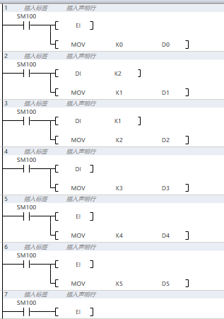
All interrupt programs can be triggered
Can trigger interrupt programs of priority 0 and priority 1
Can trigger interrupts with priority 0
Cannot trigger any interrupts
Can trigger an interrupt program with a priority of 0
Can trigger interrupt programs with priority 0 and priority 1
SIMASK/Interrupt Mask
Set interrupt pointer No. specified in (I) to the execution permission state/execution prohibition state according to the value of (s).
-[SIMASK (I) (s)]
Content, range and data type
| Parameter | Content | Range | Data type | Data type (label) |
|---|---|---|---|---|
| (I) | Interrupt program name | - | Program name | POINTER |
| (s) | Specify the enable/disable of interrupt | 0: Allow. 1: Prohibited | Signed BIN 16 bit | ANY16 |
Device used
| instruction | Parameter | Devices | Offset modification | Pulse extension | |||||||||||||||||||||||
| X | Y | M | S | SM | T(bit) | C(bit) | LC(bit) | HSC(bit) | D.b | KnX | KnY | KnM | KnS | T | C | D | R | SD | LC | HSC | K | H | E | [D] | XXP | ||
| SIMASK | Parameter 1 | Only support interrupt program name | |||||||||||||||||||||||||
| Parameter 2 | ● | ● | ● | ● | ● | ● | ● | ● | ● | ● | ● | ● | ● | ||||||||||||||
Features
• The interrupt program of the interrupt program name specified in (I) is set to the execution permission state/execution prohibited state according to the data specified in (s).
• When (s) is 0: Interrupt program execution permission status
• When (s) is 1, the execution of the interrupt program is prohibited
• Regarding the interrupt program when the power is turned on or after STOP→RUN, all interrupt programs will be executed.
• After setting interrupt prohibition, the prohibition state will be saved even if the instruction is disconnected. To restore it, write 0 to (S), turn on the instruction again, or execute STOP→RUN.
• The interrupted execution permission status/execution prohibition status will be stored in SM or SD, details as following:
(1) External Interrupt
| Register | Content | Register | Content | Register | Content | Register | Content |
|---|---|---|---|---|---|---|---|
| SM352 | X0 rising edge interrupt | SM356 | X2 rising edge interrupt | SM360 | X4 rising edge interrupt | SM364 | X6 rising edge interrupt |
| SM353 | X0 falling edge interrupt | SM357 | X2 falling edge interrupt | SM361 | X4 falling edge interrupt | SM365 | X6 falling edge interrupt |
| SM354 | X1 rising edge interrupt | SM358 | X3 rising edge interrupt | SM362 | X5 rising edge interrupt | SM366 | X7 rising edge interrupt |
| SM355 | X1 falling edge interrupt | SM359 | X3 falling edge interrupt | SM363 | X5 falling edge interrupt | SM367 | X7 falling edge interrupt |
(2) Timer interrupt
| Register | Content |
|---|---|
| SD350 to SD356 | Timer interrupt mask, each bit represents an interrupt, a total of 100 |
(3) High-speed counter interrupt
| Register | Content |
|---|---|
| SD382 to SD388 | high-speed counter interrupt mask, each bit represents an interrupt, a total of 100 |
Error code
| Error code | Content |
|---|---|
| 4084H | Data beyond 0 and 1 is input in the application instruction(s) |
| 4085H | (S) in the read application instruction exceeds the device range |
| 4189H | The SIMASK instruction specifies an interrupt program name that is not set |
Example
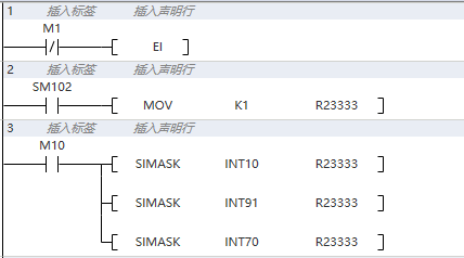
As shown in the figure: when M10 is turned on, the three interrupt programs of INT10, INT91 and INT70 are prohibited from running.
Cycle instructions
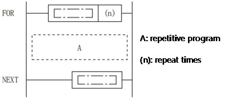
FOR to NEXT/Cycle
When the processing between the FOR to NEXT instruction is executed unconditionally (n) times, the next processing of the NEXT instruction will be performed.
Content, range and data type
| Parameter | Content | Range | Data type | Data type (label) |
|---|---|---|---|---|
| (n) | Number of repetitions between FOR to NEXT instructions | 1 to 32767 | Signed BIN 16 bit | ANY16 |
| instruction | Parameter | Devices | Offset modification | Pulse extension | |||||||||||||||||||||||
| X | Y | M | S | SM | T(bit) | C(bit) | LC(bit) | HSC(bit) | D.b | KnX | KnY | KnM | KnS | T | C | D | R | SD | LC | HSC | K | H | E | [D] | XXP | ||
| FOR | Parameter 1 | ● | ● | ● | ● | ● | ● | ● | ● | ● | ● | ● | ● | ● | |||||||||||||
Features
• When the processing between the FOR to NEXT instruction is executed unconditionally (n) times, the next processing of the NEXT instruction will be performed.
• (n) can be specified in the range of 1 to 32767. When specifying -32768 to 0, the same processing as (n)=1 will be performed.
• If you do not want to execute the processing between the FOR and NEXT instructions, use the CJ instruction to jump.
• The FOR instruction can be nested up to 5 levels.

• Do not use IRET, SRET, RET, FEND, END and other instructions to block between FOR to NEXT instructions.
• If the number of repetitions is too large, the cycle time (operation cycle) becomes longer and the watchdog timer error occurs, you need to change the watchdog timer time or reset the watchdog timer.
• The following program will become an error.

• If the FOR to NEXT instruction is repeatedly executed and ends midway, use the BREAK instruction.
Error code
| Error code | Content |
|---|---|
| 4085H | (s) read address exceeds the device range |
| 4100H | When the nesting of FOR to NEXT instructions exceeds 5 levels or the number of FOR to NEXT does not correspond |
Example
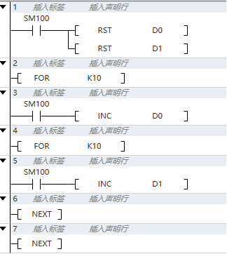
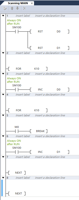
The program INC D0 will be executed 10 times, and INC D1 will be executed 100 times.
After execution, D0 will be equal to 10 and D1 will be equal to 100.
BREAK/Break Cycle
When the processing between the FOR to NEXT instruction is executed unconditionally (n) times, the next processing of the NEXT instruction will be performed.
-[BREAK]
Features
• Forcibly end the repeated processing by FOR to NEXT instructions.
• This instruction can only be between FOR to NEXT, otherwise an operation error will be reported.
• The BREAK instruction can only jump out of the loop nesting structure where the instruction itself is located.
• When the contact is connected, the loop structure of the FOR to NEXT instruction where it is located is forced to end, as shown in the figure below.
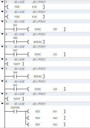
When M0 is set to ON, no matter how many cycles are left, it will directly jump to the seventh grid to execute the program.
When M4 is set to ON, no matter how many cycles are left, it will directly jump to the tenth grid to execute the program.
Error code
| Error code | Content |
|---|---|
| 4186H | BREAK instruction is not used between FOR to NEXT instructions |
Example
The program INC D0 will be executed 10 times, and INC D1 will be executed 100 times.
When M0 is OFF, D0 will be equal to 10 and D1 will be equal to 100 after execution.
When M0 is ON, the BREAK instruction is executed, and the current loop is exited. The INC D1 instruction will not be executed, and the result D1=0.
Watchdog Reset
WDT/Watchdog Timer
The watchdog timer is reset by the program.
-[WDT]
Features
• Reset the watchdog timer through the program.
• Use when the scan time exceeds the set value of the watchdog timer depending on conditions.
• For t1 from step 0 to WDT instruction, and from WDT instruction to END instruction, do not exceed the set value of the watchdog timer.

• The WDT instruction can be used more than twice in one scan.

- The watchdog timer time is set to 300ms;
- Refresh the watching timer.
Error code
There is no operation error.
Example
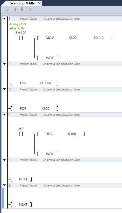
The FOR to NXET instruction loop takes a long scan period for many times, which may exceed the set watchdog timer 300ms, causing the PLC to report an error and cannot continue to run. After turning on M0, the WDT instruction will run, and the watchdog timer is updated every cycle, so that it will not report an error to execute the program normally.