07 EtherCAT
Description
EtherCAT is an open industrial field technology based on Ethernet, which has the characteristics of short communication refresh cycle, small synchronization jitters, and low hardware cost.
Master station configuration
Double-click the EtherCAT node of the project management tree to pop up the EtherCAT configuration, modify the configuration and save it.
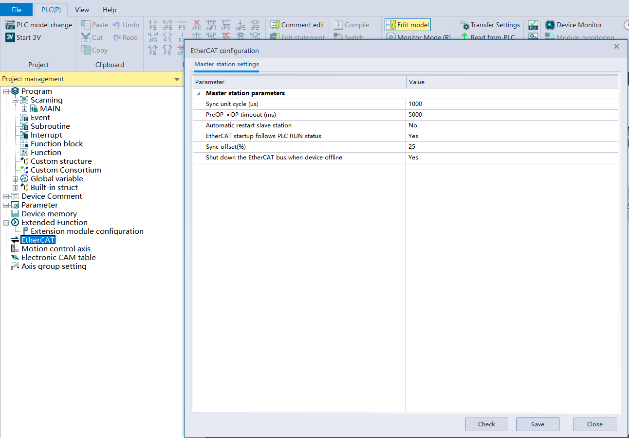
Configuration description
- Synchronous unit cycle: how long does it take to synchronize data.
- PreOP->OP timeout: the timeout from PreOP state to OP state during the initialization of OP;
- Automatically restart slave station: after it is enabled, if the slave is offline or powered off, it will try to recover to OP status;
- EtherCAT enables following PLC RUN status: after it is enabled, PLC RUN triggers EtherCAT to execute the process to OP;
- Synchronous offset: the percentage of time offset allowed during synchronization;
- Offline shutdown of EtherCAT bus: if a device is offline, the EtherCAT function will be disabled and all stations will switch to PreOP state. If automatic restart of slaves is enabled, it will be all restarted.
Import and add slaves
Import configurations
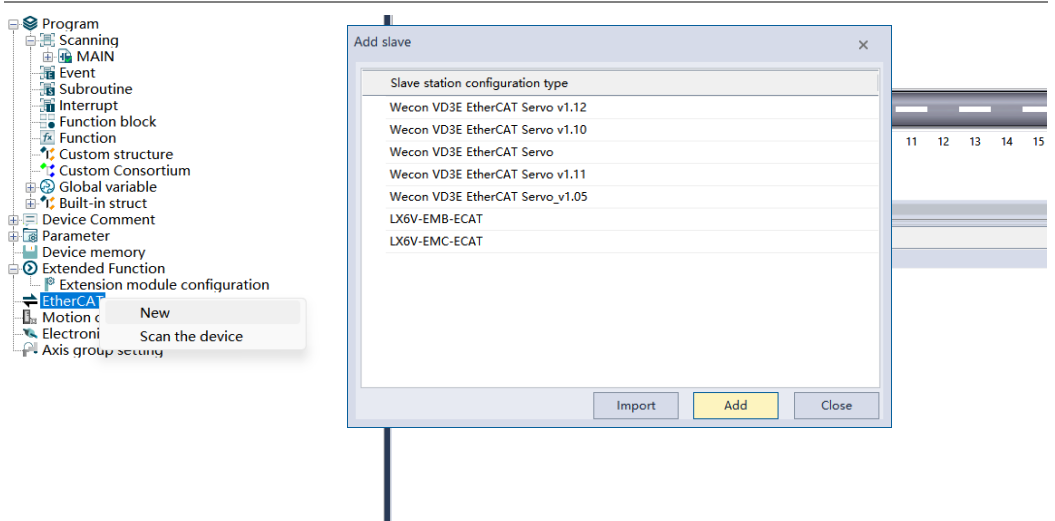
Right-click the EtherCAT node in the project management tree, click New, click the Import button in the pop-up Add Slave window, and select the EtherCAT xml file of the corresponding manufacturer to import.
Add a slave station
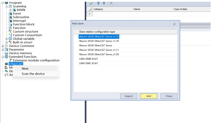
Right-click the EtherCAT node in the project management, click New, select a slave type and click Add, a new slave node will be added to the EtherCAT node in the project management, and click Close to end the operation of adding a slave.
Copy to new item
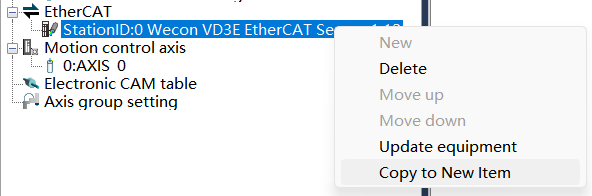
Right-click to select the slave node under the EtherCAT node in the project management, click “Copy to New Item”, and create a new slave node with exactly the same configuration as the selected node.
Slave station configuration
Delete
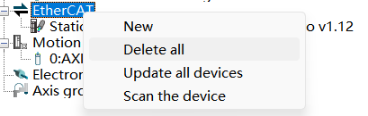
① Right-click the EtherCAT node, select [Delete all], and delete all currently created slave station configurations.

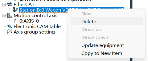
② Right-click the slave station under the EtherCAT node, select Delete, and delete the current slave station configuration.
Update devices
① Right-click the EtherCAT node and select [Update All Devices] to update the configuration information of the current EtherCAT node to the newly imported EtherCAT configuration file information.
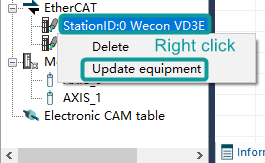
② Right-click the slave station under the EtherCAT node, select [Update equipment], and update the configuration information of the corresponding slave station node to the newly imported EtherCAT configuration file information.
Slave station parameters
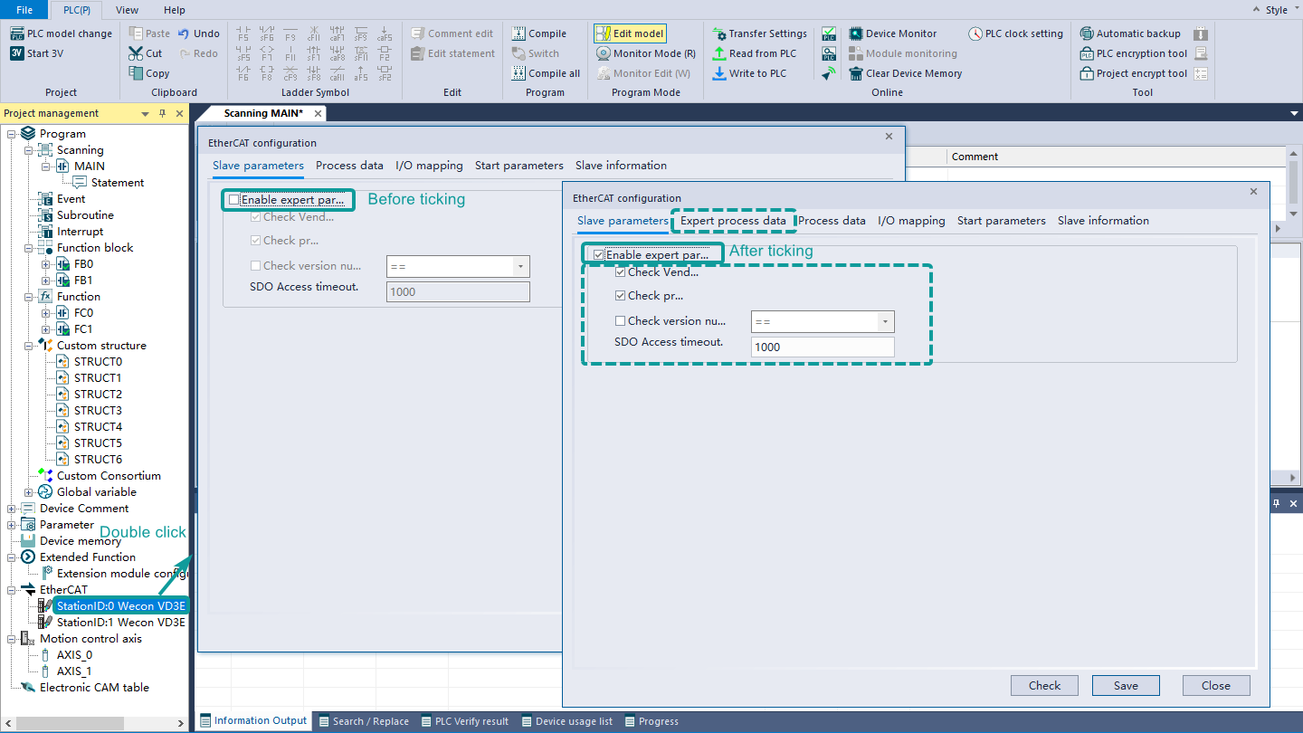
Double-click the slave station under the EtherCAT node, and the EtherCAT configuration dialog box will pop up. In the slave station parameter interface, check the enable expert parameter to use the expert process data interface and the check box and edit box below.
▪Check Vendor ID: During activation, check whether the downloaded slave configuration is consistent with the slave vendor ID connected to the PLC;
▪Check Product ID: During activation, check whether the downloaded slave configuration is consistent with the slave product ID connected to the PLC;
▪Check version number: Check whether the version numbers are consistent when activated;
▪SDO access timeout: Set the SDO access time.
Distributed clock
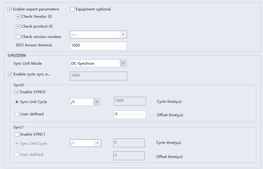
This part is used to set the synchronous operation mode of the slave station. The interface is as follows:
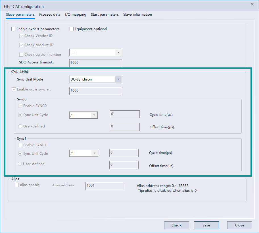
Sync unit mode: Generally, EtherCAT slave stations have FreeRun mode, running mode synchronized with input and output events (SM-Synchron), and running mode synchronized with distributed clock (DC-Synchron). Depending on the selected slave station, the options supported by the synchronous unit mode will be different.
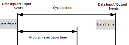
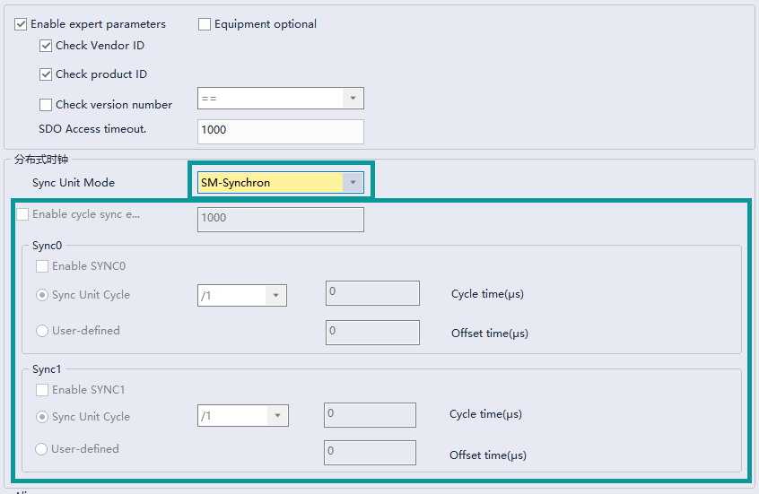
Take the Wecon VD3E EtherCAT Servo V1.11 module as an example. This module supports SM-Synchron mode, and neither SYNC0 nor SYNC1 can be set. There is only one interrupt of data input and output events inside the clock slave station. The processing logic inside the slave station is shown in the following figure:
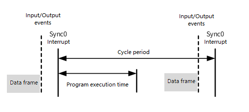
At the same time, this module also supports DC-Synchron mode. In this mode, the Sync interrupt of the slave station can be configured. DC synchronization events are enabled by default, and SYNC0 interrupt is enabled. The cycle of SYNC0 interrupt is the same as the synchronization cycle of the EtherCAT master station. SYNC1 interrupt is not enabled.
When "Enable expert parameters" is checked, select DC mode in the drop-down box, such as "DC-Synchron", and check "Enable cycle synchronization event". SYNC0 and SYNC1 groups will be restored from the disabled state to the enabled status, and SYNC0 enable button will be checked by default. The configuration is shown in the figure below:
The drop-down box selects a non-DC mode, such as "SM-Synchron", the SYNC0 and SYNC1 groups are all grayed out, and the cycle time and offset time are both 0.
Alias settings
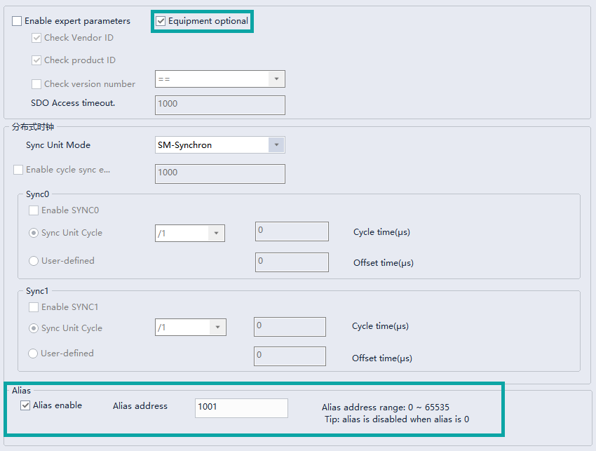
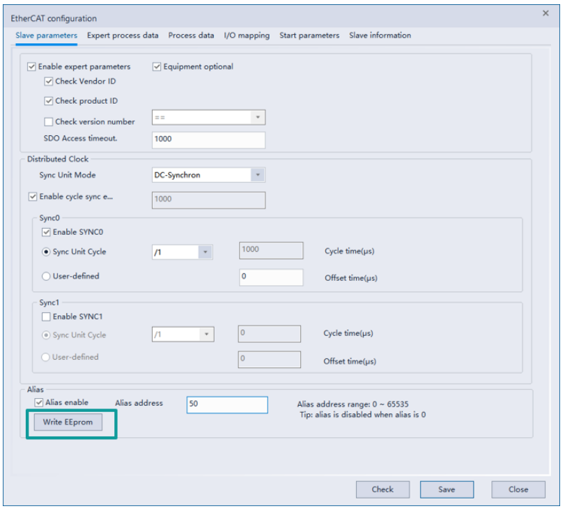
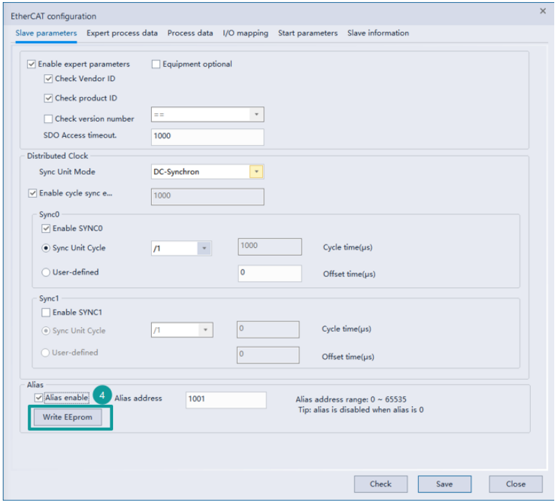
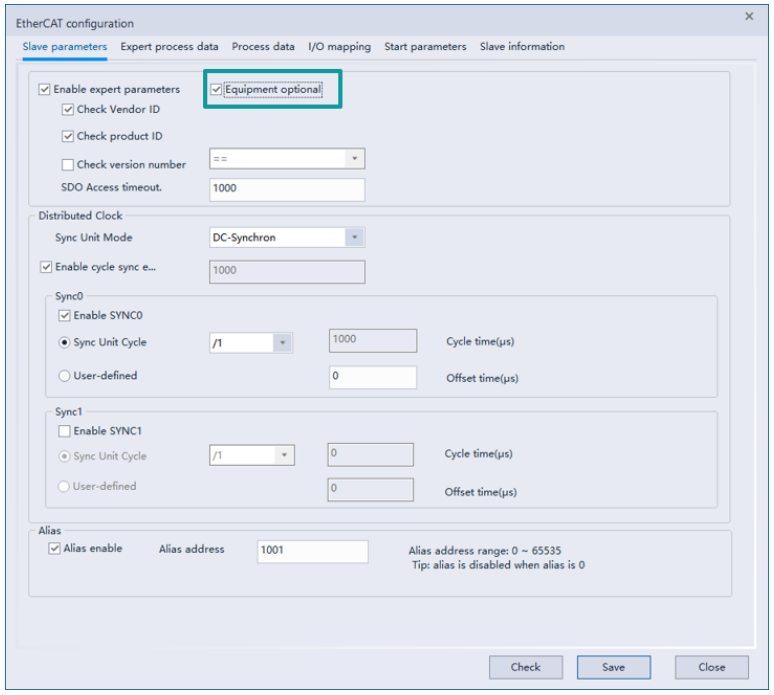
Check "Enable expert parameters" to set the slave alias, or check "Equipment optional" to force the slave to configure the alias. To use the site alias function correctly, please follow the following steps:
1. Create the configuration, uncheck "Alias Enable", and wait for the slave station to start normally after downloading the program.
2. Check "Enable expert parameters" or "equipment optional" and enter an alias.
3. In monitoring mode, click the "Write EEPROM" button and wait for the writing to complete.

4. After the writing is completed, re-power the slave station and check whether the alias was really written successfully through automatic scanning.
Expert parameters
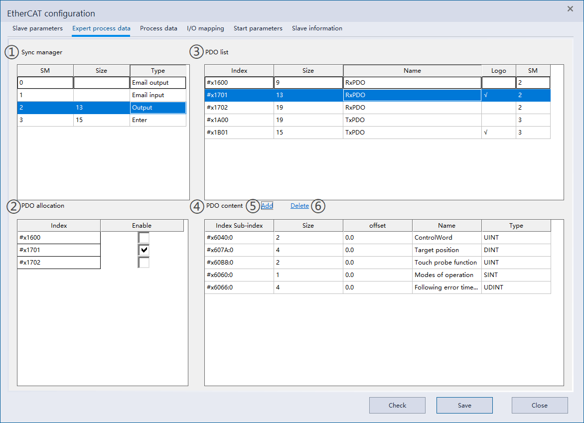
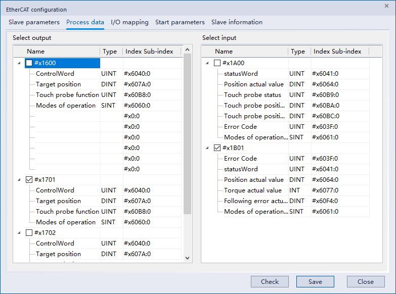
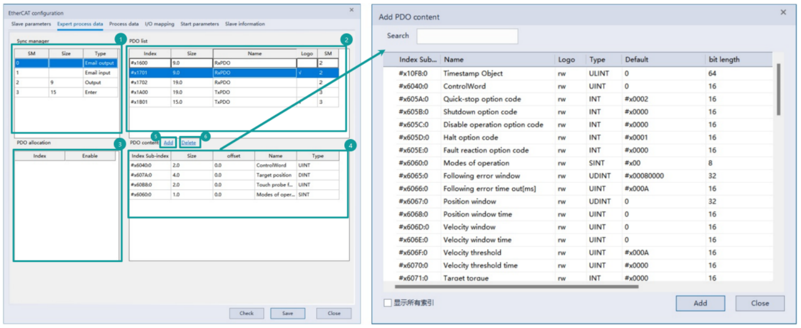
▪Select ① the synchronization manager table area, select input and output, and ② the PDO allocation table area will be updated with the PDO allocation list corresponding to the output or input of the synchronization manager;
▪Check or uncheck to enable the ②PDO allocation form area, which will be fed back to the ③PDO list;
▪Select the checked row in the ③PDO list, and the contents of the ④PDO content table will be updated;
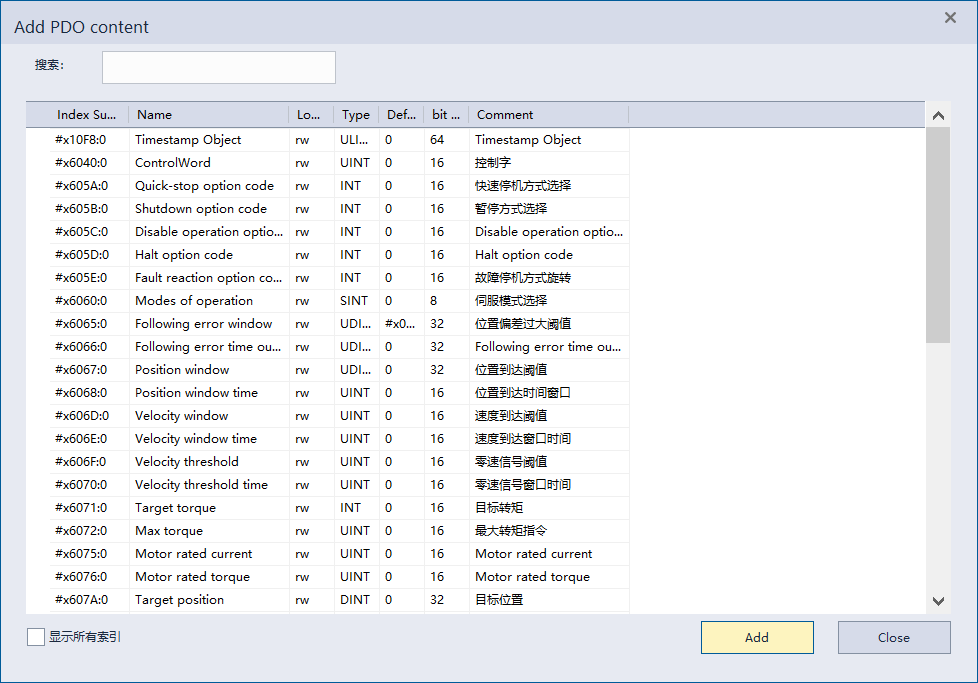
▪In the ④PDO content table, right-click the menu and select Add or click the ⑤Add button, select the content to be added in the Add PDO content interface, and then click Add;
▪After selecting the content to be deleted in the ④PDO content table, right-click the menu and select Delete or directly click the ⑥Delete button to delete.
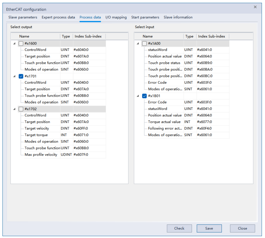
Process data
Except that the process data interface cannot customize the PDO content, other functions are basically the same as the expert process parameters.
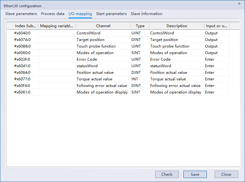
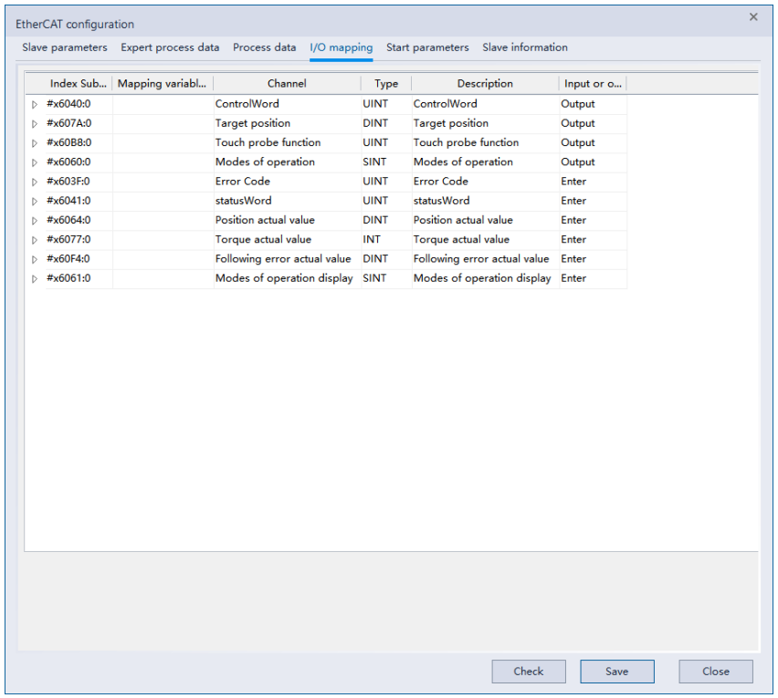
I/O mapping
For the PDO content set by the process parameters, user can select devices or variables for mapping.
Start-up parameters
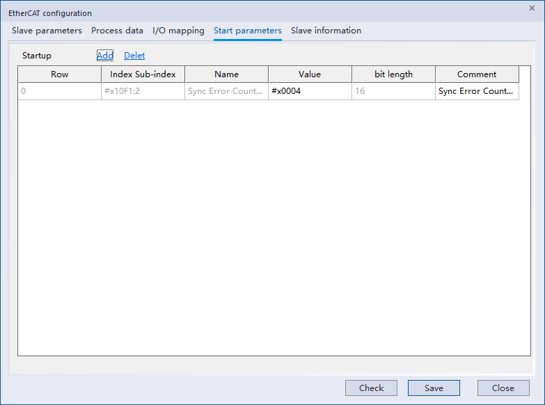
① Add
Right-click the menu to select [Add] or click [Add] directly to enter the interface for adding startup parameters, select the corresponding item, and add startup parameters.
② Delete
After selecting the parameter content to be deleted, right-click the menu and select delete or directly click the delete button to delete.
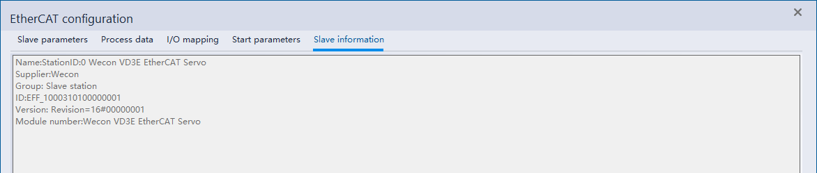
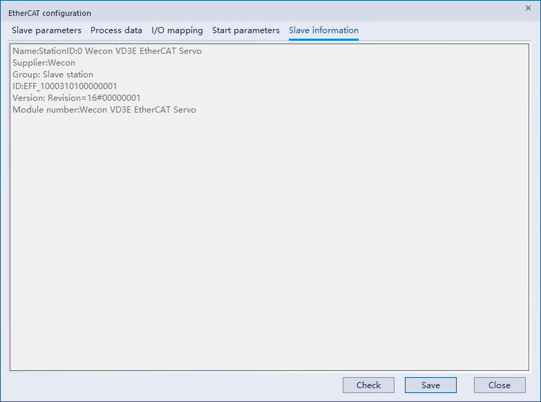
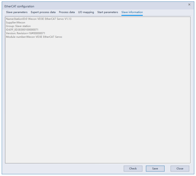
Slave information
Display slave station information.
Alias
Alias parameter configuration
Check [Enable expert parameters] and [Equipment optional] to use [Alias] function.
After [Expert parameters] enables, you can choose whether you need alias.
After [Equipment optional] enables, alias forcibly enables.
[Equipment optional] means that this device is an optional device and may not exist. When the device cannot be found, it will not run. If MC_POWER runs, it will not be successful and report error. [Alias enable] is forcibly turned on, that is, when the corresponding device must be found through alias and the product information must be checked, the product must be matched before it can be recognized normally.
If it is an alias set in [Expert mode], even if the alias is not found, the equipment of the corresponding model can run normally if it is found in order.
Example
- 5 devices: A, B, C, D, E. The link order is E, D, A, C, B, which will be searched according to aliases, and all of them correspond to configuration order. It will run normally.
| Configuration order | Alias | Link order | Alias |
| A | 1 | E | 5 |
| B | 2 | D | 4 |
| C | 3 | A | 1 |
| D | 4 | C | 3 |
| E | 5 | B | 2 |
- 5 devices: A, B, C, D, E. Check [Equipment optional], and the order of links is d, a, c, and b. When using e, the corresponding FB will report an error, but it will not affect the use and operation of other devices;
| Configuration order | Alias | Link order | Alias |
| A | 1 | D | 4 |
| B | 2 | A | 1 |
| C | 3 | C | 3 |
| D | 4 | B | 2 |
| E | 5 |
- 5 devices: A, B, C, D, E. C and E turn on [Device optional], and the link order is e, d, c, b. Since a does not turn on [Device optional] and cannot be found at the same time,When OP, it cannot be OP, the error "Device not found" will be reported.
| Configuration order | Alias | Link order | Alias |
| A | 1 | E | 5 |
| B | 2 | D | 4 |
| C | 3 | C | 3 |
| D | 4 | B | 2 |
| E | 5 |
If it is an alias set in expert mode, even if the alias is not found, the device of the corresponding model can run normally if it is found in order.
Example
5 devices: A, B, C, D, E. The link order is e, d, a, c, b.
The aliases b, d, and e are all corresponding. At this time, a and c will be found if they do not match. (After b, d, and e are matched, pull out these three units from both sides, and then it becomes: Configure the order, a, c, and find the link sequence so that a and c can be found.
| Configuration order | Alias | Link order | Alias |
| A | 1 | E | 5 |
| B | 2 | D | 4 |
| C | 3 | A | 10 |
| D | 4 | C | 30 |
| E | 5 | B | 2 |
If the aliases of a, d, and e correspond, b and c cannot be found if they do not match. (After the same removal, configure the order, b, c, search link sequence. So, c, b can't be found.)
| Configuration order | Alias | Link order | Alias |
| A | 1 | E | 5 |
| B | 2 | D | 4 |
| C | 3 | A | 1 |
| D | 4 | C | 30 |
| E | 5 | B | 20 |
Note
If [Expert mode] and [Equipment optional] are both checked, it will run according to [Equipment optional];
l At present, the first version does not support the situation that there are more linked devices than the configured ones, and there are more devices that can be linked normally;
For example, link 5 devices configured5 units, if one of them is set with [Device Optional] but there is no correspondence, it cannot be enabled at this time;
In addition, uncheck [Manufacturer id] and [Model check], although in some cases you can only check alias correspondence, and sequential matches are forced. But there is no guarantee that it will operate normally;
Except 0 aliases, aliases that can be normally corresponded are not allowed to be duplicated. Before OP, this section will be checked (SM1900 off->on Instantaneous detection), for example, during the process, it is allowed to set two identical aliases to the slave station, but after setting OP again(instruction or STOP RUN Errors will also be reported.
Alias writes to servo
In monitoring mode, click on the EtherCAT device interface in the project management interface.

At this time, the following interface appears. Different from the non-monitoring mode, [Write EEprom] appears. This button writes the alias to the corresponding servo.
The execution rules for this key are:
After OP, (SM1902 ON) will be set according to the device corresponding to the configuration. If there is no correspondence, it will prompt that the setting failed;
Before OP, (SM1902 OFF) is aliased according to the link sequence Regardless of whether the model corresponds or not, set it directly. If there is no correspondence, the setting will fail.
Simple configuration instance
When an EtherCAT device configuration exists, open the EtherCAT configuration of the corresponding slave station.
1Check [Start Expert Parameters] and [Alias Enable], and then configure the corresponding alias to be written into the "Alias Address"; 2 Save the configuration and download it to Run in PLC;
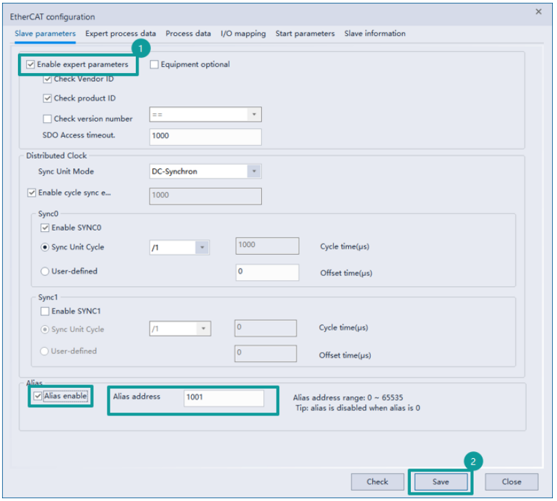
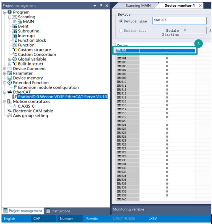
When the link sequence corresponds, the corresponding servo can still be matched. 3Open the software device monitoring interface and observe that SM1902 is ON;
Open the EtherCAT configuration interface, click [Write EEprom], and write the alias to Servo;
Restart the servo and PLC can be matched by alias.

Then check [Device optional] in edit mode.
After removing the linked EtherCAT device and re-downloading the ladder diagram that checks the optional device, the ladder diagram can still start normally. However, MC_POWER corresponding to the axis cannot be started (but no error will be reported), and the IO mapping does not work.
In the same ladder diagram, connect the corresponding equipment, and then stop->run. The corresponding device of run PLC can be used normally.
Expert parameters
. Select ① Synchronization Manager table area, select input and output, ② PDO allocation table area will be updated to synchronization manager output or the PDO allocation list corresponding to input;
. Check or uncheck “enable ② PDO allocation table area”, which will be fed back to the ③ PDO list;. Select the checked row in the ③ PDO list to update the ④ PDO content table;
. In the ④ PDO content table, right-click to select Add or click the ⑤ Add to add Select the content to be added in the PDO content interface and click Add;
. After selecting the content to be deleted in the ④ PDO content table, right-click the menu to select Delete or directly click the ⑥ Delete button to delete it.
Process Data
The process data interface is basically consistent with the expert process parameter functions except that PDO content cannot be customized.
I/O Mapping
For PDO content set by process parameters, you can select device or variables to map.
Start Parameters
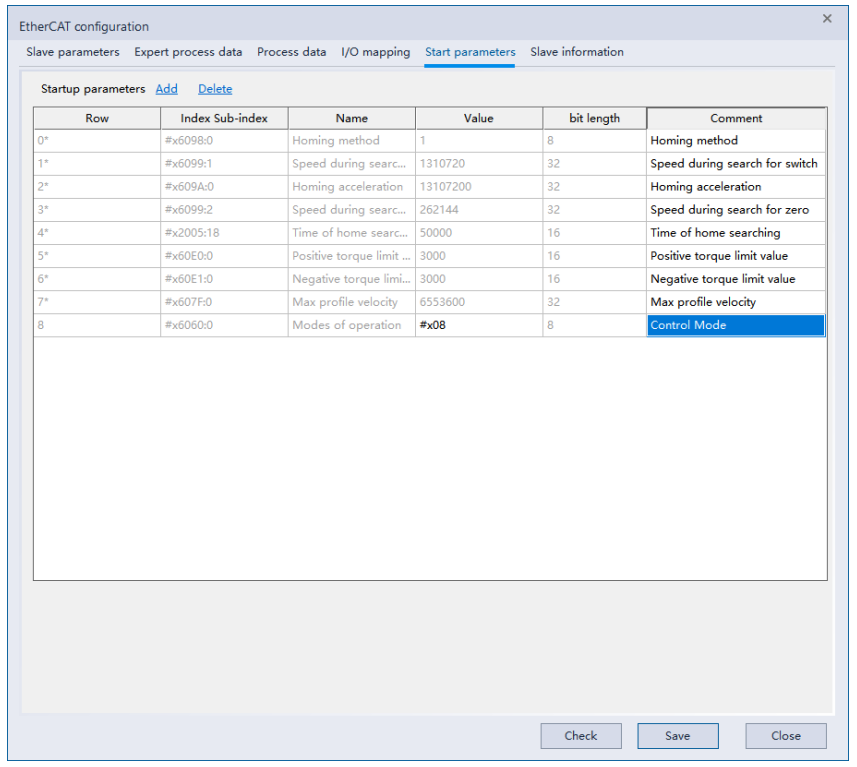
① Add
Right-click the menu to select [Add] or directly click [Add] to enter the interface for adding startup parameters, select the corresponding item, and add startup parameters. ② Delete
After selecting the parameter content to be deleted, right-click the menu to select delete or directly click “Delete”.
Slave station information
Display slave station information.
Device scanning
EtherCAT's device scanning supports direct scanning after connecting or unloading the device.
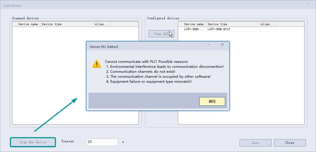
- Select the EtherCAT label, right-click the mouse button and select the scanning device in the pop-up menu.
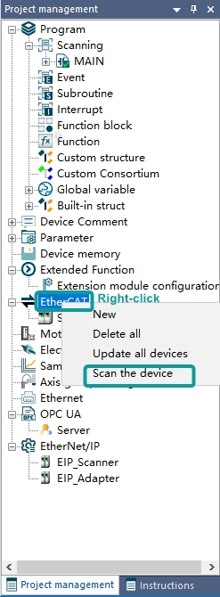
- Click the "Scan the device" button in the pop-up window. If the PLC is not connected, an error will be prompted, as shown below;
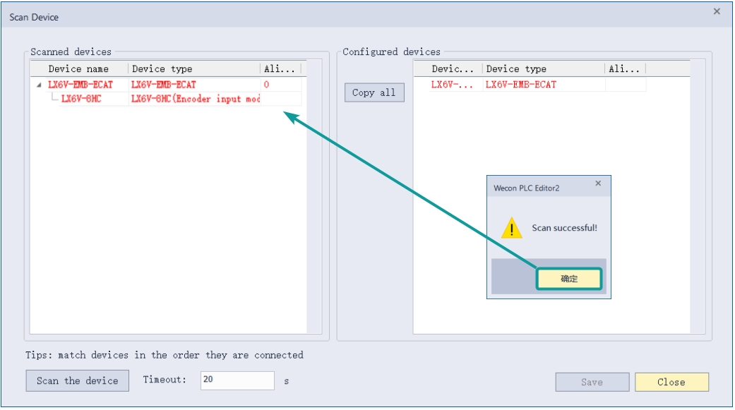
After waiting for the scan to complete, the scanned slave devices can be seen in the left side view.
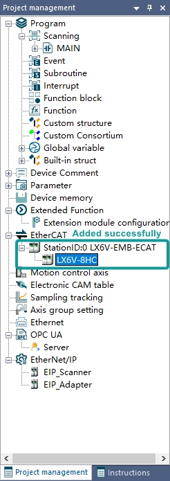
- Click [Copy all] to update the scanned devices to the currently configured configuration list, and then click [Save] to update the scanned devices to the configuration list of the project. After saving, click [Close] to update to the configuration list.
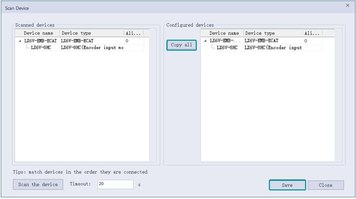
✎Note: Close the window if it is not saved, the scanned devices will not be added to the configuration list of the project!
EtherCAT instruction
ETC_READPARAMETER_COE
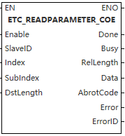
This function is mainly used to read the SDO parameters of the servo.
Content, range, data type
| Instruction | Pin type | Parameter | Variable type | Can be empty or not | Range | Description |
| ETC_READPARAMETER_COE | Input | Enable | BOOL | No | TRUE/FALSE | Read Servo SDO enable |
| SlaveID | WORD | No | 0 to range of EtherCAT slaves that can be linked | Set according to the ID configured in the interface. If the device is optional, an error will be reported even if the device does not actually exist | ||
| Index | WORD | No | 0 to 65535 | Index, fill in according to the information provided by the servo | ||
| SubIndex | WORD | No | 0 to 65535 | Sub-index, fill in according to the information provided by the servo | ||
| DstLength | WORD | No | - | Data length, fill in according to the information provided by the servo. | ||
| Output | Done | BOOL | Yes | TRUE/FALSE | When the value is obtained, Done will be set to TRUE, and if Done is not read, it will be set to FALSE | |
| Busy | BOOL | Yes | TRUE/FALSE | Busy is TRUE during reading | ||
| RelLength | WORD | Yes | - | Actual length | ||
| Data | DWORD | Yes | - | Read data | ||
| AbrotCode | DWORD | Yes | TRUE/FALSE | Interrupt code returned by the servo, refer to the EtherCAT standard document for information | ||
| Error | BOOL | Yes | TRUE/FALSE | Error | ||
| ErrorID | DWORD | Yes | See error code for details | Error code |
Device used
| Instruction | Parameter | Device | Offset modification | Double word extension | Pulse-type expansion | |||||||||||||||||||||
| X | Y | M | S | SM | T(Bit) | HSC(Bit) | D.b | KnX | KnY | KnM | KnS | T | C | D | R | SD | LC | HSC | K | H | E | [D] | DXX | XXP | ||
ETC_READ PARAMETER_COE | Enable | ● | ● | ● | ● | ● | ||||||||||||||||||||
| SlaveID | ||||||||||||||||||||||||||
| Index | ||||||||||||||||||||||||||
| SubIndex | ||||||||||||||||||||||||||
| DstLength | ||||||||||||||||||||||||||
| Done | ● | ● | ● | ● | ||||||||||||||||||||||
| Busy | ● | ● | ● | ● | ||||||||||||||||||||||
| RelLength | ||||||||||||||||||||||||||
| Data | ||||||||||||||||||||||||||
| AbrotCode | ||||||||||||||||||||||||||
| Error | ● | ● | ● | ● | ||||||||||||||||||||||
| ErrorID | ||||||||||||||||||||||||||
- Used to read the address values of the servo index and subindex, with the correct length.
- Function:
① When Enable is continuously set to ON, it will continuously read the SDO value into Data. Upon receiving a value, it will set Done to ON and append the new value to Data. If no value is read, Done will be set to OFF.
② When Enable is triggered by an edge, it will read data once. During this process, Busy is TRUE. After reading the data, it will write the obtained value to Data, at which point Done will be set to ON.
③ If the corresponding slave cannot be found after Enable is triggered, a 0x27c3 error will be reported.
④ If the corresponding index, sub-index, or length is incorrect after Enable is triggered, an error will occur. The specific error needs to be checked according to AbrotCode.
✎Note:Reading data takes time, and reading too much data at once will take a long time to update the data.
Error code
| Error code | Content |
| 0x27c3 | Axis not found (Check if the input parameters are correct) |
| 0x27D8 | SDO access length error (Check the length used in SDO read and write instructions) |
| 0x27CD | SDO read error. Check the address, retry the write operation, or increase the timeout period. |
| 0x27CC | SDO write error. Check the address, retry the write operation, or increase the timeout period. |
Example
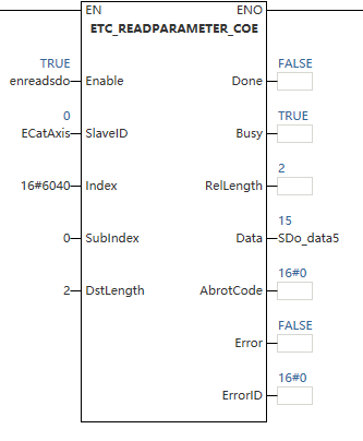
Read the value from Index 0x6064, Subindex 0, with a length of 2, and display the read value in the Data field.
ETC_WRITEPARAMETER_COE
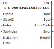
This function is mainly used to write SDO parameters to the servo drive.
Content, range, data types
| Instruction | Pin type | Parameter | Variable type | Can be empty or not | Range | Description |
| ETC_WRITEPARAMETER_COE | Input | Enable | BOOL | No | TRUE/FALSE | Read Servo SDO enable |
| SlaveID | WORD | No | 0 to range of EtherCAT slaves that can be linked | Set according to the ID configured in the interface. If the device is optional, an error will be reported even if the device does not actually exist | ||
| Index | WORD | No | 0~65535 | Index, fill in according to the information provided by the servo | ||
| SubIndex | WORD | No | 0~65535 | Sub-index, fill in according to the information provided by the servo | ||
| DstLength | WORD | No | - | Data length, fill in according to the information provided by the servo. | ||
| Output | Done | BOOL | Yes | TRUE/FALSE | When the value is obtained, Done will be set to TRUE, and if Done is not read, it will be set to FALSE | |
| Busy | BOOL | Yes | TRUE/FALSE | Busy is TRUE during reading | ||
| AbrotCode | DWORD | Yes | TRUE/FALSE | Interrupt code returned by the servo, refer to the EtherCAT standard document for information | ||
| Error | BOOL | Yes | TRUE/FALSE | Error | ||
| ErrorID | DWORD | Yes | See error code for details | Error code |
Device used
| Instruction | Parameter | Device | Offset modification | Double word extension | Pulse-type expansion | |||||||||||||||||||||
| X | Y | M | S | SM | T(Bit) | HSC(Bit) | D.b | KnX | KnY | KnM | KnS | T | C | D | R | SD | LC | HSC | K | H | E | [D] | DXX | XXP | ||
ETC_WRITE PARAMETER_COE | Enable | ● | ● | ● | ● | ● | ||||||||||||||||||||
| SlaveID | ||||||||||||||||||||||||||
| Index | ||||||||||||||||||||||||||
| SubIndex | ||||||||||||||||||||||||||
| DstLength | ||||||||||||||||||||||||||
| Done | ● | ● | ● | ● | ||||||||||||||||||||||
| Busy | ● | ● | ● | ● | ||||||||||||||||||||||
| AbrotCode | ||||||||||||||||||||||||||
| Error | ● | ● | ● | ● | ||||||||||||||||||||||
| ErrorID | ||||||||||||||||||||||||||
- Used to read the address values of the servo index and subindex, with the correct length.
- Function:
① When Enable is continuously set to ON, it will continuously read the SDO value into Data. Upon receiving a value, it will set Done to ON and append the new value to Data. If no value is read, Done will be set to OFF.
② When Enable is triggered by an edge, it will read data once. During this process, Busy is TRUE. After reading the data, it will write the obtained value to Data, at which point Done will be set to ON.
③ If the corresponding slave cannot be found after Enable is triggered, a 0x27c3 error will be reported.
④ If the corresponding index, sub-index, or length is incorrect after Enable is triggered, an error will occur. The specific error needs to be checked according to AbrotCode.
✎Note:Reading data takes time, and reading too much data at once will take a long time to update the data.
Error code
| Error code | Content |
| 0x27c3 | Corresponding slave station not found (Check if the input parameters are correct) |
| 0x27D8 | SDO access length error (Check the length used in SDO read and write instructions) |
| 0x27CD | SDO read error. Check the address, retry the write operation, or increase the timeout period. |
| 0x27CC | SDO write error. Check the address, retry the write operation, or increase the timeout period. |
Example
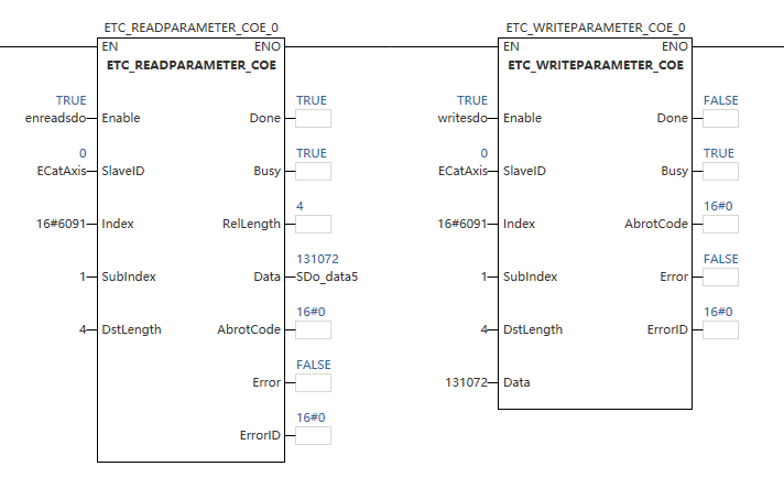
Write the value 131072 to the address of index 0x6091, subindex 1 and data length 4, read it back via the ETC_READPARAMETER_COE.
IODRVETHERCAT
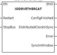
This function is mainly used to start, restart, and shut down the EtherCAT bus.
Content, range, data type
| Instruction | Pin type | Parameter | Variable type | Can be empty or not | Range | Description |
IODRV ETHERCAT | Input | Restart | BOOL | No | TRUE/FALSE | Trigger restart/start of the EtherCAT bus |
| StopBus | BOOL | No | TRUE/FALSE | Trigger shutdown of the EtherCAT bus | ||
| Output | ConfigFinished | BOOL | Yes | TRUE/FALSE | Configuration completed (TRUE) | |
| DistributedClockInSync | BOOL | Yes | TRUE/FALSE | Sync clock initialization completed (TRUE) | ||
| Error | BOOL | Yes | TRUE/FALSE | Error occurred (TRUE) | ||
| SyncInWindow | BOOL | Yes | See error code for details | Sync window initialization completed (TRUE) |
Device used
| Instruction | Parameter | Device | Offset modification | Double word extension | Pulse-type expansion | |||||||||||||||||||||
| X | Y | M | S | SM | T(Bit) | HSC(Bit) | D.b | KnX | KnY | KnM | KnS | T | C | D | R | SD | LC | HSC | K | H | E | [D] | DXX | XXP | ||
IODRV ETHERCAT | Restart | ● | ● | ● | ● | ● | ||||||||||||||||||||
| StopBus | ● | ● | ● | ● | ● | |||||||||||||||||||||
| ConfigFinished | ● | ● | ● | ● | ||||||||||||||||||||||
Distributed ClockInSync | ● | ● | ● | ● | ||||||||||||||||||||||
| Error | ● | ● | ● | ● | ||||||||||||||||||||||
| SyncInWindow | ● | ● | ● | ● | ||||||||||||||||||||||
- This function is mainly used to start, restart, and shut down the EtherCAT bus.
- Function:
① Setting Restart to TRUE or triggering it on a rising edge will execute the EtherCAT bus restart procedure. ConfigFinished, DistributedClockInSync, and SyncInWindow will be set to TRUE according to the initialization order. An initialization exception (Error) will be set to TRUE.
② Setting StopBus to TRUE will shut down the EtherCAT bus. ConfigFinished, DistributedClockInSync, and SyncInWindow will be set to FALSE.
③ Setting both Restart and StopBus to TRUE simultaneously will be considered an exception, and Error will be set to TRUE. The error code will be output from the PLC error address.
✎Note: Reading data takes time, and reading too much data at once will take a long time to update the data.
Error code
| Error code | Content |
| 0x27c3 | Corresponding slave station not found (Check if the input parameters are correct) |
| 0x27D8 | SDO access length error (Check the length used in SDO read and write instructions) |
| 0x27CD | SDO read error. Check the address, retry the write operation, or increase the timeout period. |
| 0x27CC | SDO write error. Check the address, retry the write operation, or increase the timeout period. |
Example
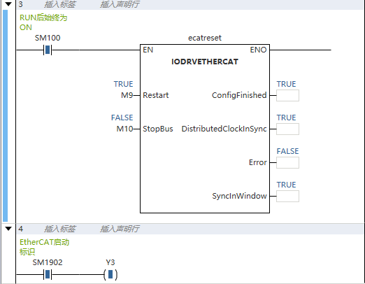
Setting Restart to TRUE starts the EtherCAT master, and SM1902 is set to TRUE after successful startup.
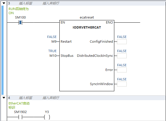
Setting StopBus to TRUE shuts down the EtherCAT master, and SM1902 is set to FALSE synchronously.
AbrotCode exception codes
| AbrotCode exception codes | Corresponding exception |
| 0x00000000 | No SDO error |
| 0x05030000 | Toggle bit not changed |
| 0x05040000 | SDO timeout |
| 0x05040001 | Instruction specifier unknown |
| 0x05040005 | Insufficient memory event explanation |
| 0x06010000 | Access not supported |
| 0x06010001 | Write-only entry |
| 0x06010002 | Read-only entry |
| 0x06010003 | Entry cannot be written because Subindex 0 is not 0 |
| 0x06010004 | Object cannot be accessed |
| 0x06020000 | Object does not exist |
| 0x06040041 | Object cannot be mapped to PDO |
| 0x06040042 | Mapped object exceeds PDO |
| 0x06040043 | Parameter incompatible |
| 0x06040047 | Device incompatible |
| 0x06060000 | Hardware error |
| 0x06070010 | Parameter length error |
| 0x06070012 | Parameter too long |
| 0x06070013 | Parameter too short |
| 0x06090011 | Subindex (entry) does not exist |
| 0x06090030 | Value exceeded |
| 0x06090031 | Value too large |
| 0x06090032 | Threshold too small |
| 0x06090033 | Detected module identification list (0xF030) does not match configured module identification list |
| 0x06090036 | Less than minimum value |
| 0x08000000 | General error |
| 0x08000020 | Data not readable/writable event explanation |
| 0x08000021 | Data inaccessible due to local control |
| 0x08000022 | Event explanation: unable to read or write data in current state |
| 0x08000023 | Object not in object dictionary |