09 High Speed Counter
High-speed Counter (Encoder axis) Introduction
High-speed counter axis introduction
The high-speed counter is implemented in the form of encoder axis in LX6 series PLC, subsequent collectively referred to as the encoder axis. It supports 4-axis 32-bit high-speed counter, AB phase 1/2/4 times frequency, pulse/direction and single-phase counting. The counting signal support external pulse input or internal 100us/1ms/10ms clock counting, and supports touch probe and high-speed comparison output functions.
Create encoder axis
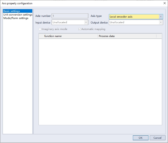
Step: "Project Management"->"Motion control axis"->"Right click"->"Add Axis"
"Axis type" select "Local encoder Axis"
Encoder axis user unit and conversion
The encoder axis decoding the encoder signal by pulse unit, and the encoder axis command uses common measurement units such as millimeters, degrees, inches, etc., which we call it user unit. The number of pulses can be converted into user unit through conversion, and user unit can be defined as equipment-related units (millimeters, revolutions, etc.) according to actual applications.
The parameters to be set for unit conversion are as follows:
| Parameter name | Function |
|---|---|
| Pulses of motor/encoder for one rotation | Set pulses of motor for one rotation according to encoder resolution |
| With gearbox or not | Specify whether or not to use gearbox |
| Movement amount of motor/encoder for one rotation | Workpiece movement amount of motor for one rotation without gearbox |
| Movement amount of worktable for one rotation | Workpiece movement amount of motor for one rotation with gearbox |
| Gear ratio numerator | Set the gear ratio of workpiece side |
| Gear ratio denominator | Set the gear ratio of motor side |
In gear drive, the drive axis is usually called input axis, and the driven axis is called output axis. Therefore, the numerator of the gear ratio represents the speed of the input axis (usually also represents the gear driven by the input axis), and the denominator represents the speed of the output axis (usually also represents the gear driven by the output axis). If the gear ratio is a: b, it means that for a revolution of the input axis, the output axis will rotate b revolutions.
For example, servo motor drives worktable to move by connecting screw rod through reducer, counts encoder to feedback worktable position by PLC controller, and counts encoder pulse by counter, taking pulse as unit; If the counter axis represents the table position, it is in millimeters. Therefore, in the program, the user unit of the counter axis is uniformly expressed in the user unit.
The conversion relationship between user unit and pulse is as follows:
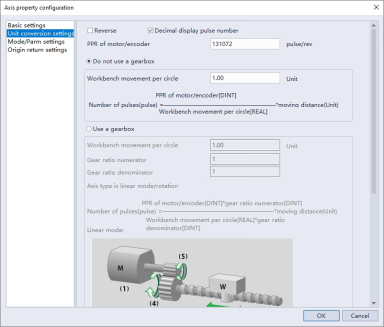
The number of pulses for one revolution of the motor/encoder: In the input box, 16# indicates a hexadecimal number. If the encoder output 10000 pulses per revolution, the corresponding hexadecimal value is 2710, then enter 16#2710.
Working stroke setting: The working stroke can be set without or with a gearbox.
Without gearbox:
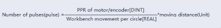
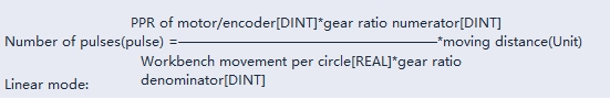
When the gearbox is not used, the conversion formula from user unit to pulse unit is as follows:
For example, if the encoder rotates one circle and the corresponding working axis rotates one circle, the user unit is one revolution, then the working stroke of the motor/encoder one circle rotation can be set to 1.
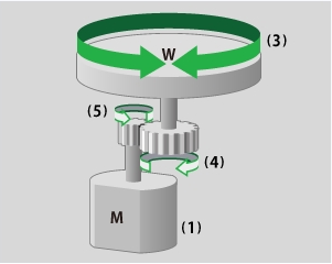
·With gearbox:
The calculation formula from user unit to pulse unit is as follows:
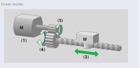
Wherein (1) is a servo motor, (3) is a workpiece, (4) is the gear ratio denominator, and (5) is the gear ratio numerator.
The calculation formula from user unit to pulse unit is as follows:
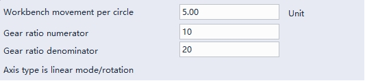
For instance: The servo motor drives the worktable to move through the reducer connected by the screw. The working stroke of the screw rotating once is 5mm, and the reduction ratio is 20:10. The corresponding input axis (motor) needs to rotate 20 turns every time the output axis rotates once. Therefore, the gear ratio numerator can be set as 20, and the gear ratio denominator can be set as 10. Before the motor rotation is transmitted to the output axis (screw), the amplification of the gear can ensure the required distance for the worktable to move. The settings are as follows:
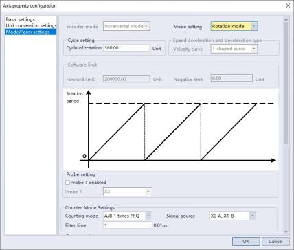
Typical working condition in rotation mode is shown in the following figure:
Wherein (1) is a servo motor, (3) is a workpiece, (4) is the gear ratio denominator, and (5) is the gear ratio numerator.
The calculation formula from user unit to pulse unit is as follows:
Work mode setting
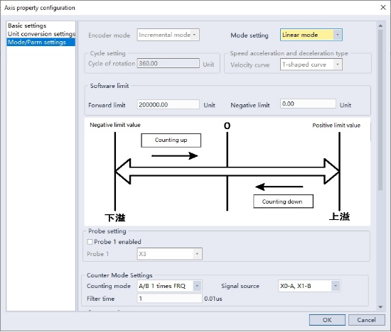
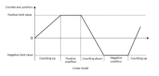
Linear mode
The position of the encoder axis changes between the negative limit value and the positive limit value. After the position of the encoder axis reaches the limit value, if continue to input the same direction pulse, the counter axis will report an overflow error, and the position of the counter axis will remain unchanged. After encoder report an overflow error, if input reverse pulse, the encoder axis will reverse count and overflow error removed.
In linear mode, the negative and positive position limits of the encoder axis can be set in the interface, and the position unit is the user unit. The negative limit value must be less than or equal to 0, and the positive limit value must be greater than or equal to 0.
Since the high-speed counter is a 32-bit counter, the negative limit value and the positive limit value must be in the 32-bit integer range [-2147483648, 2147483647] after being converted into pulse units.
In linear mode, the high-speed counter works in the closed range of [negative limit value, positive limit value]. When the direction is negative, the count value decreases in the negative direction, and after reaching the negative limit value, the count value no longer decreases; When the direction is positive, the count value increases in the positive direction, and after reaching the positive limit value, the count value no longer increases.
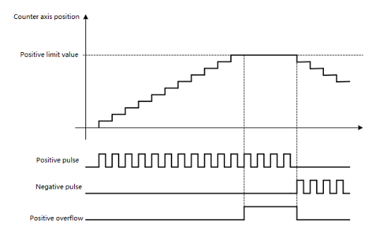
Forward pulse counting
In linear mode, input positive pulse, after the encoder axis position increment count reaches the limit value, if continue to input positive pulse will cause the encoder axis reports a positive overflow error, and the encoder axis position value remains unchanged. Input negative pulse, encoder axis position will count down and positive overflow error will be removed.
Reverse pulse counting
In linear mode, input negative pulse, after the encoder axis position countdown reaches the limit value, if continue to input negative pulse will cause the encoder axis reports a negative overflow error, and the encoder axis position value remains unchanged. Input positive pulse, encoder axis position will count up and negative overflow error will be cleared.

Rotation mode
The position of the encoder axis changes cyclically in the rotation period. When counting up, the position of the encoder axis reaches the maximum of the rotation period and then becomes 0. When counting down, the position of the encoder axis reaches 0 and then decreases from the maximum of the rotation period. In rotation mode, the rotation period of the counter axis can be set in the interface, and the period unit is the user unit.
Since the high-speed counter is 32-bit counter, the rotation period must be in the 32-bit integer range [-2147483648.2147483647, 2147483647] after being converted into pulse units.
Setting counter parameters
Overview
Local encoder axis supports multiple signal counting modes, A/B phase (1/2/4 times frequency), pulse + direction, single phase counting.
Signal source: According to different counting modes, user can select different signal sources.

The signal source input ports supported in each counting mode are shown in the following table. Different local encoder axis can select the same signal source input port:
| Counting mode | AB phase | Pulse + Direction | Single phase counting |
|---|---|---|---|
| X0 | A phase | Pulse | Pulse |
| X1 | B phase | Direction | Pulse |
| X2 | A phase | Pulse | Pulse |
| X3 | B phase | Direction | Pulse |
| X4 | A phase | Pulse | Pulse |
| X5 | B phase | Direction | Pulse |
| X6 | A phase | Pulse | Pulse |
| X7 | B phase | Direction | Pulse |
| 100us | × | × | Pulse |
| 1ms | × | × | Pulse |
| 10ms | × | × | Pulse |
When using touch probe or preset function, encoder axis is divided into two groups, namely, X0 ~ X3 is counting group 1 and X4 ~ X7 is counting group 2. The same signal source in counting group can only be used in one encoder axis, that is, when the touch probe function of counting group 1 is enabled, X3 is occupied and cannot be used as signal source of other counting modes. Touch probes and preset functions cannot be used by internal signal sources.
| Counting mode | AB phase | Pulse + Direction | Single phase counting |
|---|---|---|---|
| X0 | A phase | Pulse | Pulse |
| X1 | B phase | Direction | × |
| X2 | Touch probe | Touch probe | Touch probe |
| X3 | Preset | Preset | Preset |
| X4 | A phase | Pulse | Pulse |
| X5 | B phase | Direction | Pulse |
| X6 | Touch probe | Touch probe | Touch probe |
| X7 | Preset | Preset | Preset |
| 100us | × | × | Pulse |
| 1ms | × | × | Pulse |
| 10ms | × | × | Pulse |
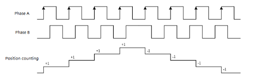
A/B phase mode
In the A/B phase mode, the encoder generates two quadrature phase pulse signals with a phase difference of 90 degrees, namely A-phase signal and B-phase signal. When the A-phase signal advances the B-phase signal, the counter increases the count; When the B-phase signal advances the A-phase signal, the counter counts down.
A/B phase pulse can be set to work in 1 time frequency mode, 2 times frequency mode or 4 times frequency mode.
In A/B phase 1 time frequency mode, only the rising edge of phase A pulse is counted, as shown in the following figure:
In A/B phase 2 times frequency mode, the rising/falling edge of phase A pulse is counted, as shown in the following figure:
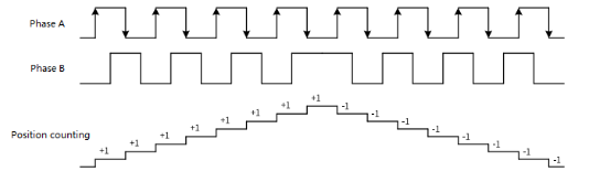
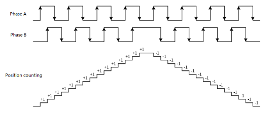
In A/B phase 4 times frequency mode, the rising/falling edge of phase A pulse is counted, as shown in the following figure:
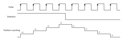
Pulse + direction mode
In this mode, when the direction signal is ON, the high-speed counter increases the count of the pulse signal, and when the direction signal is OFF, the high-speed counter decreases the count of the pulse signal, as shown in the following figure:
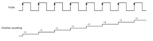
Single-phase counting mode
In this mode, the high-speed counter increases the count of the pulse signal, on the rising edge of the input pulse, the position count is increased by 1.
Touch probe setting
Each encoder axis supports one external input to latch the current value of the counter to realize the touch probe function. The counting group 1 fixed use terminal X3, and the counting group 2 fixed use terminal X7.
After the touch probe is enabled, the current count value will be saved after the touch probe is triggered, and the touch probe position of the counter axis will be read through the HC_TouchProbe function block instruction.

Preset terminal input
By checking the preset enable to enable the external input preset counter value, the counting group one fixed use terminal X2, and the counting group two fixed use terminal X6.
After the preset function is enabled, the encoder axis position is preset by external input through HC_Preset function block instruction.

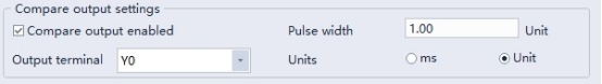
Compare output terminal settings
After "comparison output enabled" is checked, hardware can output when comparison is equal, which can be realized without software processing, with high real-time performance and output response up to microsecond level.
● After the comparison output function is checked and cooperated with function block instruction, the output is controlled to be ON by hardware circuit when the comparison is equal, Y0~Y7 can be arbitrarily selected as the output terminal, and the pulse width of the output to be ON can be selected as time unit or user unit.
● Each local encoder axis is equipped with a comparison output function, which can configure the input terminal and output pulse width according to the demand.
● After the configuration is completed, through HC_Compare, HC_ArrayCompare and HC_StepCompare function block instructions, the axis position comparison output is realized.
● When ms is selected as the unit, the time setting range is 0.1~6553.5ms. When Unit is selected, the set value should be in the range of 1~65535 after being converted into pulse Unit.
The comparison output is directly output through the hardware control port, not through the software processing, so the status of comparison output cannot be displayed through the Y device in the program. The Y device and the comparison output are controlled as OR relationship to the output port. If the Y device is continuously controlled as ON state, the actual port output is kept as ON.
HC Axis Control
HC_COUNTER High Speed Counter Enable
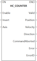
HC_COUNTER
This function block is used to control the start or stop of the high speed counter.
Content, range and data type
| Instruction | Parameter | Variable type | Can it be empty | Range | Description |
|---|---|---|---|---|---|
| HC_COUNTER | Enable | BOOL | No | TRUE FALSE | High speed counter preset value function block enabledHigh speed counter preset value function block enabled |
| Invert | BOOL | Yes | TRUE FALSE | Negative counting | |
| Axis | WORD | No | 0~65535 | Axis name/axis number: specify the local encoder axis to operate | |
| Valid | BOOL | Yes | TRUE FALSE | Valid status: entering the counting status is ON | |
| Position | LREAL | Yes | - | Current position: user unit | |
| Velocity | LREAL | Yes | - | Current velocity: user unit | |
| Direction | BOOL | Yes | TRUE FALSE | Counting direction (TRUE: Forward, FALSE: Reverse) | |
| CommandAborted | BOOL | Yes | TRUE FALSE | Execute interrupt | |
| Error | BOOL | Yes | TRUE FALSE | Error | |
| ErrorID | DWORD | Yes | Check [ErrorID] for details | Error code |
Device used
| Instruction | Parameter | Devices | Offset modification | DWORD expansion | Pulse expansion | |||||||||||||||||||||
|---|---|---|---|---|---|---|---|---|---|---|---|---|---|---|---|---|---|---|---|---|---|---|---|---|---|---|
| X | Y | M | S | SM | T (Bit) | HSC (Bit) | D.b | KnX | KnY | KnM | KnS | T | C | D | R | SD | LC | HSC | K | H | E | [D] | DXX | XXP | ||
| HC_COUNTER | Enable | ● | ● | ● | ● | ● | ||||||||||||||||||||
| Invert | ● | ● | ● | ● | ● | |||||||||||||||||||||
| Axis | ● | ● | ||||||||||||||||||||||||
| Valid | ● | ● | ● | ● | ||||||||||||||||||||||
| Position | ||||||||||||||||||||||||||
| Velocity | ||||||||||||||||||||||||||
| Direction | ● | ● | ● | ● | ||||||||||||||||||||||
| CommandAborted | ● | ● | ● | ● | ||||||||||||||||||||||
| Error | ● | ● | ● | ● | ||||||||||||||||||||||
| ErrorID | ||||||||||||||||||||||||||
Function
The HC_COUNTER function block can count the current counter axis position, measure the current velocity in real time and display the current counting direction.
The counter axis position is set only according to the current counting mode and varies within the range of the counter axis mode, and the position unit is Unit.
Invert parameter (Negative counting)
The counting direction of the counter is set by the Invert parameter. The definition of counting directions for different counting modes are shown in the following figure. When changing the setting of Invert, it will take effect directly if the function block is enabled.
| Invert | Phase A/B | Pulse + Direction | CW/CCW | Single phase counting |
|---|---|---|---|---|
| FALSE | Phase A is ahead of Phase B to count up. Phase B is ahead of Phase A to count down. | Direction signal Vil count down Direction signal VIH count up | Phase A counting up. Phase B counting down. | Counting up |
| TRUE | Phase A is ahead of Phase B to count down. Phase B is ahead of Phase A to count up. | Direction signal Vil count up Direction signal Vol count down | Phase A counting down. Phase B counting up. | Counting down |
Description
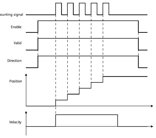
Take the "pulse + direction" mode as an example. When the direction signal = ON/Invert=FALSE or the direction signal = OFF/Invert=TRUE, the counter is counting up, as shown in the following figure:
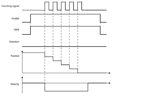
Take the "pulse + direction" mode as an example. When the direction signal = ON/Invert=TRUE or the direction signal = OFF/Invert=FALSE, the counter is counting down, as shown in the following figure:
Error code
| Error code | Content |
|---|---|
| 0x00400005 | Counting position exceeds the positive limit value. |
| 0x00400006 | Counting position exceeds negative limit value. |
| 0x00700005 | Axis undefined or invalid axis number |
| 0x00800008 | Modify the axis number when the function block is running. |
Example
Application example
The counter axis speed is the real-time speed, and the speed unit is Unit/s. The minimum speed that can be measured by the counter axis is the speed corresponding to one pulse of the counter in 1s. For instance, when one pulse of the counter corresponds to 0.01 Unit, the minimum speed that can be measured is 0.01 Unit/s.
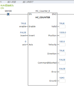
For example: When the current function block Enable in the above figure is ON, update the current encoder axis position and velocity, display the counting direction, and measure the current input pulse speed in the AXIS_0 is 100 Unit/s and the current position is 1559.0 Unit.
HC_PRESET High speed counter preset value
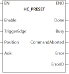
HC_PRESET
Set the counter value to the preset value according to the preset trigger condition set.
Content, range and data type
| Instruction | Parameter | Variable type | Can it be empty | Range | Description |
|---|---|---|---|---|---|
| HC_PRESET | Enable | BOOL | No | TRUE FALSE | High speed counter preset enabled |
| TriggerEdge | WORD | Yes | 0~1 | Trigger edge 0: Instruction Enable rising edge triggers 1: External X rising edge triggers | |
| Position | LREAL | No | - | Preset position: user unit | |
| Axis | WORD | No | 0~65535 | Axis name/axis number: specify the local encoder axis to operate | |
| Done | BOOL | Yes | TRUE FALSE | Completed | |
| Busy | BOOL | Yes | TRUE FALSE | Executing | |
| CommandAborted | BOOL | Yes | TRUE FALSE | Execution interrupt | |
| Error | BOOL | Yes | TRUE FALSE | Error | |
| ErrorID | DWORD | Yes | Check "ErrorID" for details | Error code |
Device used
| Instruction | Parameter | Devices | Index modification | DWORD expansion | Pulse expansion | |||||||||||||||||||||||
|---|---|---|---|---|---|---|---|---|---|---|---|---|---|---|---|---|---|---|---|---|---|---|---|---|---|---|---|---|
| X | Y | M | S | SM | T (Bit) | HSC (Bit) | D.b | KnX | KnY | KnM | KnS | T | C | D | R | SD | LC | HSC | K | H | E | [D] | DXX | XXP | ||||
| HC_PRESET | Enable | ● | ● | ● | ● | ● | ||||||||||||||||||||||
| TriggerEdge | ● | ● | ||||||||||||||||||||||||||
| Position | ||||||||||||||||||||||||||||
| Axis | ● | ● | ||||||||||||||||||||||||||
| Done | ● | ● | ● | ● | ||||||||||||||||||||||||
| Busy | ● | ● | ● | ● | ||||||||||||||||||||||||
| CommandAborted | ● | ● | ● | ● | ||||||||||||||||||||||||
| Error | ● | ● | ● | ● | ||||||||||||||||||||||||
| ErrorID | ||||||||||||||||||||||||||||
Function
Enable HC_PRESET function block and the counter axis position is assigned according to the preset trigger condition.
TriggerEdge parameter
Select the rising edge of instruction enable or external X input to trigger preset function.
| Parameter | Settings | Definition |
|---|---|---|
| TriggerEdge | 0 | Enable rising edge triggering |
| 1 | External X rising edge trigger |
When selecting external X input trigger as preset condition, it needs to see preset function in counter parameter setting. Select input terminal and trigger condition, X2 and X6 for input terminal and rising edge trigger for trigger condition.
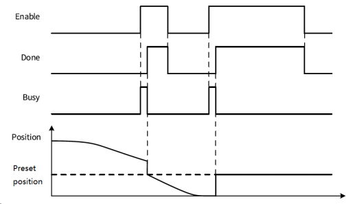
Description
The instruction Enable is triggered on the rising edge (TriggerEdge=0), and the instruction sequence diagram is shown in the following figure:
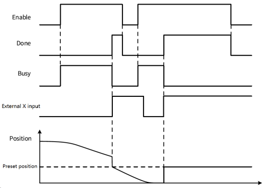
External X interrupt triggers. Take rising edge trigger (TriggerEdge=1) as an example, and the instruction sequence diagram is shown in the following figure:
| Error code | Content |
|---|---|
| 0x007000000 | Set the trigger edge to external X edge trigger, but the preset function of axis configuration interface is not enabled |
| 0x00700005 | Axis undefined or invalid axis number |
| 0x00700008 | High speed counter of local encoder axis is not enabled |
| 0x00800006 | Set the preset position out-of-limit value/set the trigger edge parameter out-of-range |
| 0x00800008 | Modify the axis number when the function block is running. |
Example
Application example
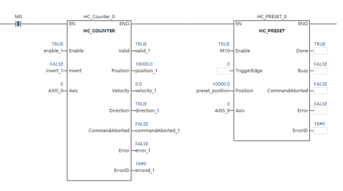
Set the preset trigger condition as Enable rising edge trigger (TriggerEdge=0). When the preset condition is met, modify the current HC_COUNTER axis position as the preset position. At this time, the current position read by the HC_COUNTER function block is the preset position.
HC_TOUCHPROBE High speed counter touch probe
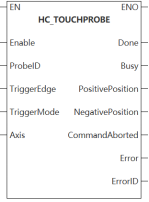
HC_TOUCHPROBE
According to the set trigger mode and conditions, record the counter value when the signal is triggered.
Content, range and data type
| Instruction | Parameter | Variable type | Can it be empty | Range | Description |
|---|---|---|---|---|---|
| HC_TOUCHPROBE | Enable | BOOL | No | TRUE FALSE | High speed counter preset enable |
| ProbeID | WORD | No | 0 | Touch probe ID 0: Touch probe 1 | |
| TriggerEdge | WORD | No | 1~3 | Trigger edge 1: External X rising edge triggers 2: External X falling edge triggers 3: External X rising or falling edge triggers | |
| TriggerMode | WORD | Yes | 0~1 | Trigger mode 0: Single triggers 1: Continuous triggers | |
| Axis | WORD | No | 0~65535 | Axis name/axis number: specify the local encoder axis to operate | |
| Done | BOOL | Yes | TRUE FALSE | Completed | |
| Busy | BOOL | Yes | TRUE FALSE | Executing | |
| PositivePosition | LREAL | Yes | - | Rising edge latch position: user unit | |
| NegativePosition | LREAL | Yes | - | Falling edge latch position: user unit | |
| CommandAborted | BOOL | Yes | TRUE FALSE | Execute interrupt | |
| Error | BOOL | Yes | TRUE FALSE | Error | |
| ErrorID | DWORD | Yes | Check "ErrorID" for details | Error code |
Device used
| Instruction | Parameter | Devices | Offset modification | DWORD expansion | Pulse expansion | |||||||||||||||||||||
|---|---|---|---|---|---|---|---|---|---|---|---|---|---|---|---|---|---|---|---|---|---|---|---|---|---|---|
| X | Y | M | S | SM | T (Bit) | HSC (Bit) | D.b | KnX | KnY | KnM | KnS | T | C | D | R | SD | LC | HSC | K | H | E | [D] | DXX | XXP | ||
| HC_TOUCHPROBE | Enable | ● | ● | ● | ● | ● | ||||||||||||||||||||
| ProbeID | ● | ● | ||||||||||||||||||||||||
| TriggerEdge | ● | ● | ||||||||||||||||||||||||
| TriggerMode | ● | ● | ||||||||||||||||||||||||
| Axis | ● | ● | ||||||||||||||||||||||||
| Done | ● | ● | ● | ● | ||||||||||||||||||||||
| Busy | ● | ● | ● | ● | ||||||||||||||||||||||
| PositivePosition | ||||||||||||||||||||||||||
| NegativePosition | ||||||||||||||||||||||||||
| CommandAborted | ● | ● | ● | ● | ||||||||||||||||||||||
| Error | ● | ● | ● | ● | ||||||||||||||||||||||
| ErrorID | ||||||||||||||||||||||||||
Function
Enable the HC_TOUCHPROBE function block instruction to latch the counter axis position value when the external input trigger condition is valid.
Each counter axis only supports one touch probe. When using, it needs to check the corresponding touch probe function in the counter parameter setting. Select the input terminal and trigger mode and condition. The input terminal can be set as X3 or X7.
Description
TriggerEdge parameter
The touch probe trigger edge can be set. The rising edge trigger position is latched in the output parameter PositivePosition. The falling edge trigger position is latched in the output parameter NegativePosition.
| Parameter | Settings | Definition |
|---|---|---|
| TriggerEdge | 1 | External X rising edge triggers |
| 2 | External X falling edge triggers | |
| 3 | External X rising or falling edge triggers |
TriggerMode parameter
Single trigger and continuous trigger modes can be set.
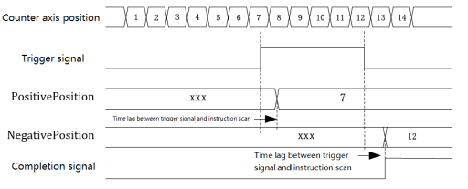
In single trigger mode, when the function block Enable is valid and external input trigger condition disappears, the counter axis position is latched and the completion signal is output. The touch probe position latches the counter axis position in real time according to the trigger edge, which is not affected by program execution. According to the scan period, the latch position is updated to the instruction output parameter when the program scanning executes to the latch instruction.
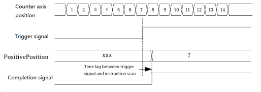
Rising edge single trigger mode
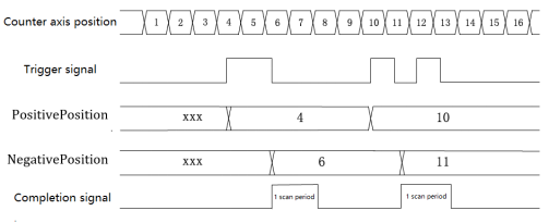
In continuous trigger mode, when the function block instruction Enable is valid and the external input trigger condition disappears, the counter axis position is latched and the completion signal is output. The valid time is 1 scan period. When the completion signal becomes OFF and the external input trigger condition is valid, the counter axis position will continue to be latched, and the completion signal with valid time of 1 scan period will be output. The counter axis position is not latched if an external input trigger condition is valid during the 1 scan period when the completion signal is valid.
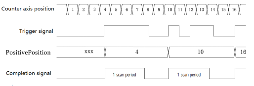
Rising edge continuous trigger mode
When using the dual-edge trigger mode, the completion signal is output when both the rising and the falling edges are triggered to complete the latch. In single trigger mode, the completion signal lasts until the instruction is completed. In continuous trigger mode, the valid time of completion signal is 1 scan period. The trigger latch signal is not responded to within 1 scan period when the completion signal is valid.
Rising and falling edges single trigger mode
Rising and falling edge continuous trigger mode
Sequence diagram
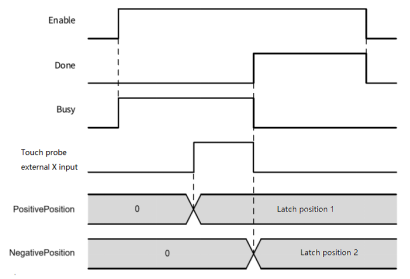
External X rising edge trigger (TriggerEdge=1), single trigger mode (TriggerMode=0), and the instruction sequence diagram is shown in the following figure.
External X falling edge trigger (TriggerEdge=2), single trigger mode (TriggerMode=0), and the instruction sequence diagram is shown in the following figure.
External X rising and falling edges triggering (TriggerEdge=3), single trigger mode (TriggerMode=0), and the instruction sequence diagram is shown in the following figure.
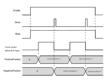
External X rising and falling edges triggering (TriggerEdge=3), continuous trigger mode (TriggerMode=1), and the instruction sequence diagram is shown in the following figure.
Error code
| Error code | Content |
|---|---|
| 0x007000000 | Touch probe of axis configuration interface is not enabled |
| 0x00700005 | Axis undefined or invalid axis number |
| 0x00800006 | Setting errors from trigger edge/trigger mode/touch probe ID |
| 0x00800008 | Modify the axis number when the function block is running. |
Example
Application example
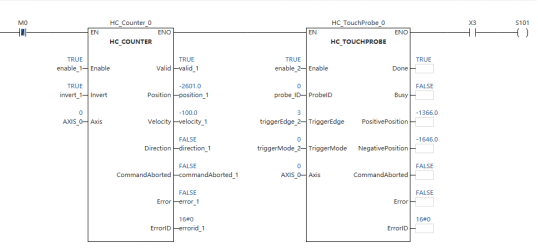
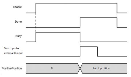
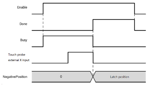
- In the axis configuration interface, the touch probe is enabled and the configuration pin is X3. Set the trigger mode to single trigger (TriggerMode = 0), and the trigger edge is external X rising and falling edges trigger (TriggerEdge = 3)
- When the function block Enable enables, Busy is set to TRUE.
- When X3 detects the rising edge, latch position to PositivePosition; When X3 detects the falling edge, latch position to NegativePosition. At this time, the execution of this function block is completed, and the Busy status is set to False and Done is set to TRUE.
HC_COMPARE High speed counters comparison
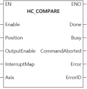
HC_COMPARE
The touch probe counter count reaches the specified value.
Content, range and data type
| Instruction | Parameter | Variable type | Can it be empty | Range | Description |
|---|---|---|---|---|---|
| HC_COMPARE | Enable | BOOL | No | TRUE FALSE | High speed counter comparison enabled |
| Position | LREAL | No | - | Comparison position: user unit | |
| OutputEnable | BOOL | Yes | TRUE FALSE | Hardware output enabled FALSE: No hardware output TRUE: Using hardware output | |
| InterruptMap | POINTER | Yes | - | Interrupt mapping: interrupts are generated and associated when the comparison value matches the count value. The interrupt name can be input directly, for instance: IRQ0: associate interrupt IRQ0 None: not associate interrupt | |
| Axis | WORD | No | 0~65535 | Axis name/axis number: specify the local encoder axis to operate | |
| Done | BOOL | Yes | TRUE FALSE | Completed | |
| Busy | BOOL | Yes | TRUE FALSE | Executing | |
| CommandAborted | BOOL | Yes | TRUE FALSE | Execution interrupt | |
| Error | BOOL | Yes | TRUE FALSE | Error | |
| ErrorID | DWORD | Yes | Check "ErrorID" for details | Error code |
Device used
| Instruction | Parameter | Devices | Offset modification | DWORD expansion | Pulse expansion | |||||||||||||||||||||
|---|---|---|---|---|---|---|---|---|---|---|---|---|---|---|---|---|---|---|---|---|---|---|---|---|---|---|
| X | Y | M | S | SM | T (Bit) | HSC (Bit) | D.b | KnX | KnY | KnM | KnS | T | C | D | R | SD | LC | HSC | K | H | E | [D] | DXX | XXP | ||
| HC_COMPARE | Enable | ● | ● | ● | ● | ● | ||||||||||||||||||||
| Position | ||||||||||||||||||||||||||
| OutputEnable | ● | ● | ● | ● | ● | |||||||||||||||||||||
| InterruptMap | ||||||||||||||||||||||||||
| Axis | ● | ● | ||||||||||||||||||||||||
| Done | ● | ● | ● | ● | ||||||||||||||||||||||
| Busy | ● | ● | ● | ● | ||||||||||||||||||||||
| CommandAborted | ● | ● | ● | ● | ||||||||||||||||||||||
| Error | ● | ● | ● | ● | ||||||||||||||||||||||
| ErrorID | ||||||||||||||||||||||||||
Function
Enabling HC_COMPARE to achieve a single position comparison of the counter axis.
Description
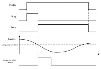
Using hardware output (OutputEnable=TRUE), the instruction sequence diagram is shown in the following figure.
Error code
| Error code | Content |
|---|---|
| 0x007000000 | OutEnable is ON, but axis configuration interface comparison output is not enabled. |
| 0x00700005 | Axis undefined or invalid axis number |
| 0x00800006 | The set comparison position is out of limit. |
| 0x00800008 | Modify the axis number when the function block is running. |
Example
Application example
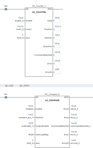
- Set the comparison position as 100, configure the interrupt mapping program (InterruptMap = IRQ0), configure the hardware output enabled (outputEnable = TRUE), and enable the function block (Enable = TRUE);
- When the counter axis position reaches 100, the comparison interrupt is triggered, and the interrupt IRQ0 is called. If the hardware output is enabled at this time, the pulse of set pulse width is output by the corresponding Y output point.
HC_ARRAYCOMPARE High speed counter array comparison
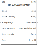
HC_ARRAYCOMPARE
Sequentially detect whether the counter count value is equal to the specified array sequence.
Content, range and data type
| Instruction | Parameter | Variable type | Can it be empty | Range | Description |
|---|---|---|---|---|---|
| HC_ARRAYCOMPARE | Enable | BOOL | No | TRUE FALSE | High speed counter comparison enabled |
| PositionArray | ARRAY OF LREAL | No | - | Comparison position array: user unit | |
| ArrayLength | WORD | No | 1~32 | Array length | |
| OutputEnable | WORD | Yes | TRUE FALSE | Hardware output enabled FALSE: No hardware output TRUE: Using hardware output | |
| InterruptMap | POINTER | Yes | - | Interrupt mapping: when the comparison value matches the count value, an interrupt is generated and associated. Interrupt name can be input directly. IRQ0: associate interrupt IRQ0 None: not associate interrupt | |
| Axis | WORD | No | 0~65535 | Axis name/axis number: specify the local encoder axis to operate | |
| Done | BOOL | Yes | TRUE FALSE | Completed | |
| Busy | BOOL | Yes | TRUE FALSE | Executing | |
| NextIndex | WORD | Yes | 0~32 | Next comparison position index | |
| CommandAborted | BOOL | Yes | TRUE FALSE | Execution interrupt | |
| Error | BOOL | Yes | TRUE FALSE | Error | |
| ErrorID | DWORD | Yes | Check "Error code" for details | Error code |
Device used
| Instruction | Parameter | Devices | Index modification | DWORD expansion | Pulse expansion | |||||||||||||||||||||
|---|---|---|---|---|---|---|---|---|---|---|---|---|---|---|---|---|---|---|---|---|---|---|---|---|---|---|
| X | Y | M | S | SM | T (Bit) | HSC (Bit) | D.b | KnX | KnY | KnM | KnS | T | C | D | R | SD | LC | HSC | K | H | E | [D] | DXX | XXP | ||
| HC_ARRAYCOMPARE | Enable | ● | ● | ● | ● | ● | ||||||||||||||||||||
| PositionArray | ||||||||||||||||||||||||||
| ArrayLength | ● | ● | ||||||||||||||||||||||||
| OutputEnable | ● | ● | ● | ● | ● | |||||||||||||||||||||
| InterruptMap | ||||||||||||||||||||||||||
| Axis | ● | ● | ||||||||||||||||||||||||
| Done | ● | ● | ● | ● | ||||||||||||||||||||||
| Busy | ● | ● | ● | ● | ||||||||||||||||||||||
| NextIndex | ● | ● | ||||||||||||||||||||||||
| CommandAborted | ● | ● | ● | ● | ||||||||||||||||||||||
| Error | ● | ● | ● | ● | ||||||||||||||||||||||
| ErrorID | ||||||||||||||||||||||||||
Function
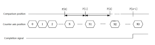
Enable HC_ARRAYCOMPARE to achieve continuous multi-position comparison of the counter axis.
Description
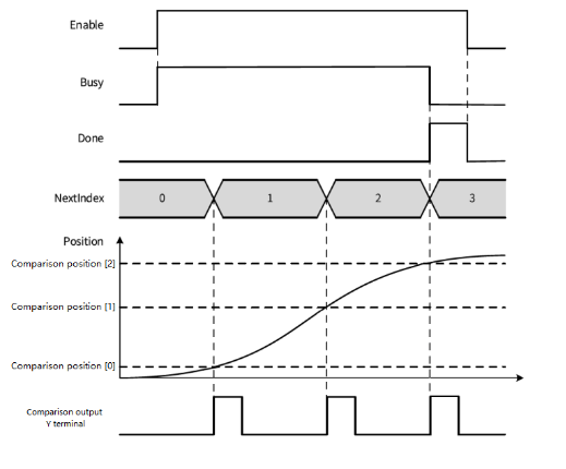
When the function block Enable is valid, the counter axis position is compared with the first position of the array. When the comparison is equal, it is compared with the next position of the array. The ArrayLength parameter in the function block is used to set the array length. When the comparison of all array positions set by the array length is completed, the signal is continuously output and the multi-position continuous comparison is completed.
The output parameter NextIndex indicates the next comparison position index, namely the number of equal comparisons that have been completed.
Sequence diagram
Compare the three positions (ArrayLength=3), using hardware output (OutputEnable=TRUE), and the instruction sequence diagram is shown in the following figure.
Error code
| Error code | Content |
|---|---|
| 0x007000000 | OutEnable is ON, but axis configuration interface comparison output is not enabled. |
| 0x00700005 | Axis undefined or invalid axis number. |
| 0x00800006 | The comparison array is not set or the length of the array is set incorrectly. |
| 0x00800008 | Modify the axis number when the function block is running. |
Example
Application example
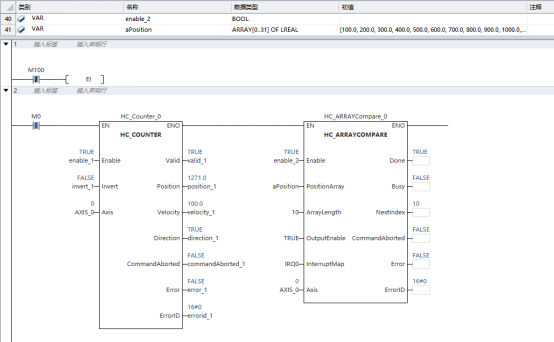
Set array parameters of current comparison position and array length n (ArrayLength=32 is allowed at the longest). When the function block Enable is enabled, the current comparison position is set to PositionArray Index 0 position value. When the current count value position is equal to the comparison position, the comparison interrupt is triggered, and the interrupt program IRQ0 specified by InterruptMap parameter is called. If the hardware output is enabled (OutputEnable=TRUE), pulse of a specific width pulse is generated in the corresponding Y point. If the comparison of all positions in the array is completed, Done completion flag will continue to be TRUE.
HC_STEPCOMPARE high speed counters equidistant comparison
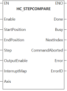
HC_STEPCOMPARE
Sequentially and continuously compares the counter count values with equidistant consecutive values within a specified range.
Content, range and data type
| Instruction | Parameter | Variable type | Can it be empty | Range | Description |
|---|---|---|---|---|---|
| HC_STEPCOMPARE | Enable | BOOL | No | TRUE FALSE | High speed counter comparison enabled |
| StartPosition | LREAL | No | - | Start position: user unit | |
| EndPosition | LREAL | No | - | End position: user unit | |
| Step | LREAL | No | Positive LREAL | Spacing: user unit | |
| OutputEnable | BOOL | Yes | TRUE FALSE | Hardware output enabled FALSE: No hardware output TRUE: Using hardware output | |
| InterruptMap | POINTER | Yes | - | Interrupt mapping: when the comparison value matches the count value, an interrupt is generated and associated. Interrupt name can be input directly. IRQ0: associate interrupt IRQ0 None: not associate interrupt | |
| Axis | WORD | No | 0~65535 | Axis name/axis number: specify the local encoder axis to operate | |
| Done | BOOL | Yes | TRUE FALSE | Completed | |
| Busy | BOOL | Yes | TRUE FALSE | Executing | |
| NextIndex | WORD | Yes | 0~65535 | Next comparison position index | |
| CommandAborted | BOOL | Yes | TRUE FALSE | Execution interrupt | |
| Error | BOOL | Yes | TRUE FALSE | Error | |
| ErrorID | DWORD | Yes | Check "Error code" for details | Error code |
Function
Enable HC_STEPCOMPARE to achieve the comparison between counter axis and equidistant continuous position.
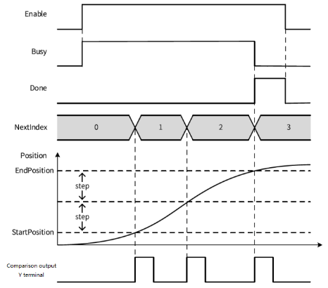
Description
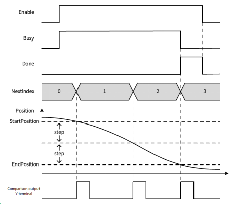
When the function block Enable is valid, the counter axis position is compared with the StartPosition position. When the comparison is equal, the comparison continues after increasing or decreasing the Step spacing in the comparison position. When the last comparison position is completed in equidistant comparison, the signal is continuously output.
Output parameter NextIndex
Indicate the index of the next comparison position, and the index starts from 0. (0 represents the first comparison position.) Therefore, the index is exactly equal to the number of comparison positions that have been completed.
Sequence diagram
Using hardware output (OutputEnable=TRUE), StartPosition<EndPosition, the instruction sequence diagram is shown in the following figure.
Using hardware output (OutputEnable=TRUE), StartPosition<EndPosition, the instruction sequence diagram is shown in the following figure.
Error code
| Error code | Content |
|---|---|
| 0x007000000 | OutEnable is ON, but axis configuration interface comparison output is not enabled |
| 0x00700005 | Axis undefined or invalid axis number |
| 0x00800000 | The number of comparison positions exceeds 65535, and the equidistant comparison is not completed. |
| 0x00800006 | Setting start position, end position and spacing error |
| 0x00800008 | Modify the axis number when the function block is running. |
Example
Application example
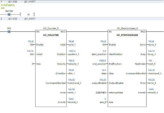
When the function block is enabled, the current comparison position is set to the specified position value of StartPosition. When the current count value position is equal to the comparison position, the comparison interrupt is triggered, and the interrupt program specified by the InterruptMap parameter is called. If the hardware output is enabled (OutputEnable=TRUE), the corresponding Y point will generate a pulse with a specific pulse width. When the current position exceeds the end position, the completion signal is continuously output.