PLC Editor2 Help (LX6)
Overview
Compared with LX5CPU series, LX6CPU series has new FB/FC function. The following text describes the new or changed part of the software to support FB/FC function. For other functions, please refer to the “LX6V Series Software Help Document” in PLC Editor2 software.
Programming
Overall Introductions
Toolbar
Add ladder diagram symbol menu for inserting series/parallel operation blocks:

Project Management
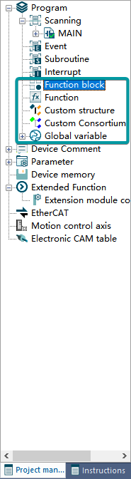
Add function blocks, functions, custom structures, custom unions, and global variables:
Ladder Diagram Editing
The program page is divided into the upper and lower areas of variable table and ladder diagram editing:
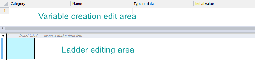
Variables can be created, deleted, and moved up and down in the variable editing area. For detailed operation of variables, please refer to 4 Variable.
Users can write programs in the ladder diagram editing area. After selecting a node in the network, elements such as contacts, operation blocks, and coils can be inserted through the ladder diagram symbols, the instruction editing window, and shortcut keys on the toolbar, or existing elements can be modified and deleted.
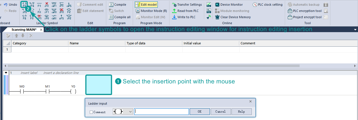
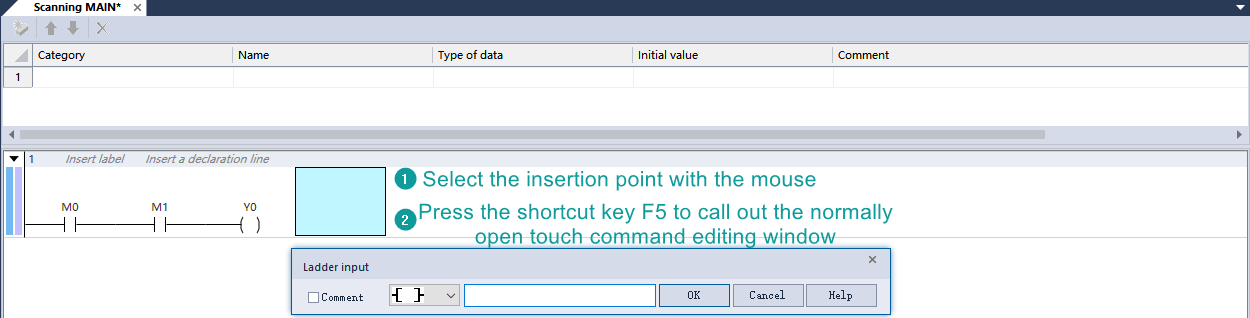
1) Instruction editing
Method 1: insert ladder diagram symbol;
Method 2: insert by shortcut key;
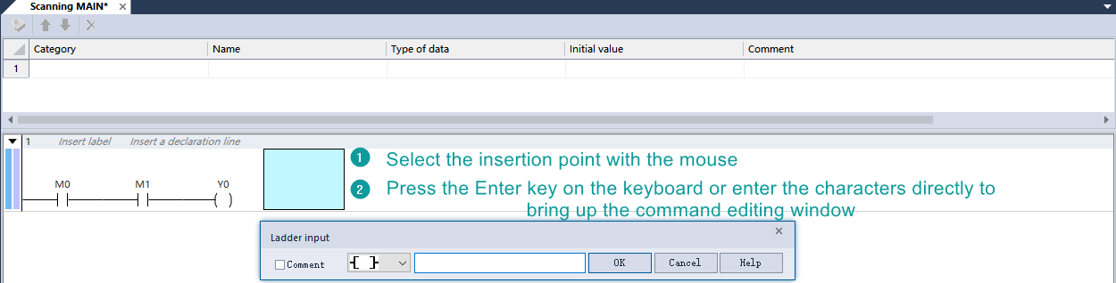
Method 3: click Enter or directly input characters.
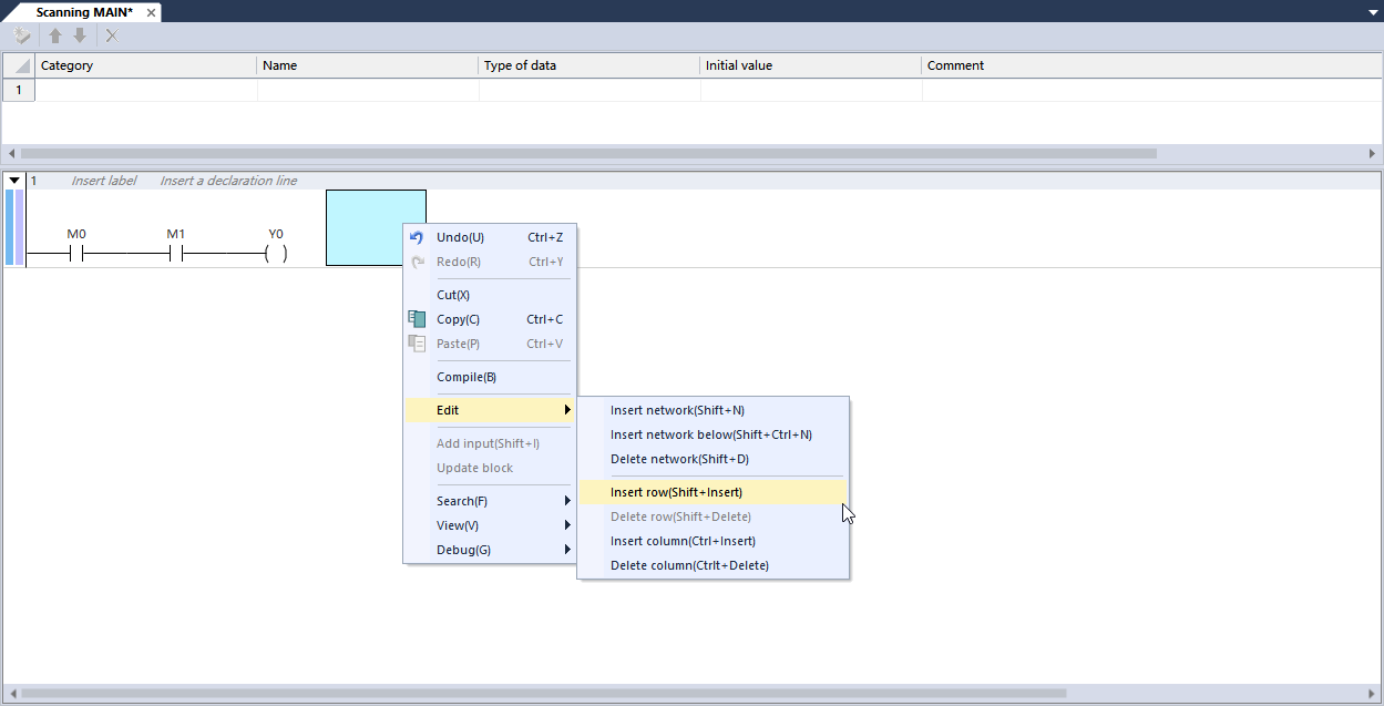
2) Row and column editing/network editing
Description of Programming Restrictions
- FC does not support the use of FB;
- Array indexing supports variables, but array nesting is not supported. For example: array[var] is allowed, array[array[var] is not allowed;
FB/FC does not support the use of combined device as variables;
- FB/FC, structure/union support up to 6 levels of nesting;
- Support variables used by contacts, coils, FB/FC, and application instructions;
- Variable names are not case-sensitive, so A1 and a1 are the same variable;
Do not support the use of device T/C/HSC/LC as BOOL input and output parameters of FB/FC.
Function Blocks and Functions (FB/FC)
Function Blocks (FB)
Function block can encapsulate a part program that is reused in a program into a general program block, which can be called repeatedly in a program. Using function blocks in programming can improve the efficiency of program development, reduce programming errors, and improve program quality.
Function blocks can produce one or more values when executed, and retain their own special internal variables. The controller execution system allocates memory to the internal status variables of the Function Blocks, and these internal variables constitute their own state characteristics. For the input variable value of the same parameter, there may be different internal state variables, and different calculation results will be obtained.
The basic steps of using a function block are: create a new function block -> program a function block -> instantiate a function block -> run a function block.
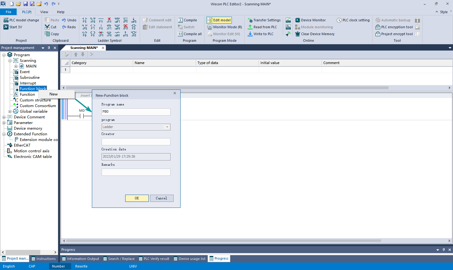
Create a New Function Block
Create a new function block via PLC Editor2 software.
Right-click the "Function Block" node in the project management area, select the New, enter the function block name and other information in the pop-up dialog box, and click "OK" to complete the creation of the function block.
Function Block Programming
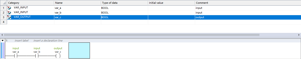
Function blocks only support ladder diagram programming. Double-click the newly created function block under the "Function Block" node to enter the function block program editing interface.
There is no difference between the function block program editing interface and the common program editing interface, and there is a local variable definition window in both.
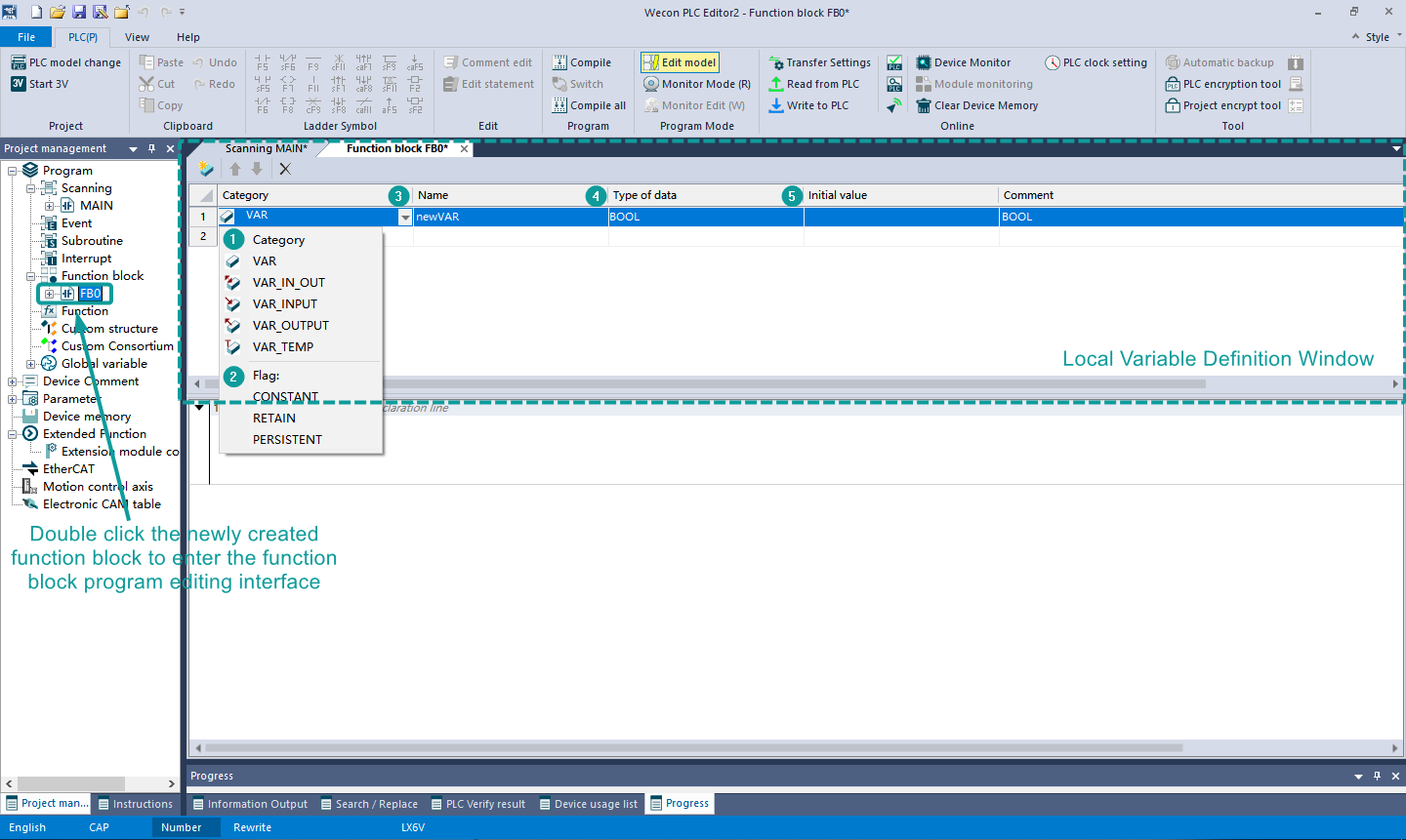
① Category: Properties of function block variables.
| Category | Category description | Description |
|---|---|---|
| VAR | Local variable | It is only valid in this logic block and cannot be accessed externally |
| VAR_IN_OUT | Input and output variable | Input and output variables can not only be passed into the called logic block, but also can be modified inside the called logic block |
| VAR_INPUT | Input variable | This parameter is provided by the logic block that calls it and command passed to the logic block is entered |
| VAR_OUTPUT | Output variable | Provide parameters to the logic block that calls it, output structure data from the logic block |
| VAR_TEMP | Temporary variables | Variables used for program and function block internal storage, and when the block is called each time, temporary variables are initialized |
② Symbol
| Category | Category description | Description |
|---|---|---|
| CONSTANT | Constant | During the running of the program, this data can only be read but not modified |
| RETAIN | Reserved | This variable will be saved after power-off, and the initialization operation will be performed when the initial value is set. |
| PRESISTENT | Save | This variable will be saved after power-off, and the initialization operation will not be performed when the initial value is set. This variable will only be cleared when the PLC memory is cleared |
③ Name: the name of the variable. Refer to the input constraints of the variable for the name constraints.
④ Data type: The variable data type supports BOOL, BYTE, INT, DINT, REAL and so on, and user can also define array variables, structures, and union. When using a structure variable, user needs to create structure members in the structure of the global variable.
⑤ Initial value: Set the initial data at the start of variable execution.
The function block program uses ladder diagram programming. In the function block program, functions (FC) or function blocks (FB) can be called, and up to 6 levels of nesting are supported.
In addition to variables, function block programs can also use devices as global variables. The current ladder diagram can use variable contacts, coils, function blocks/functions and some 5V instructions. (For details, please refer to "LX6V PLC Programming Manual")
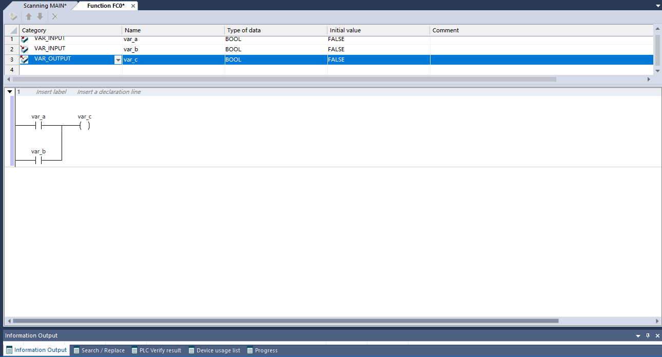
Example: Encapsulating AND with FB
Function block instantiation call
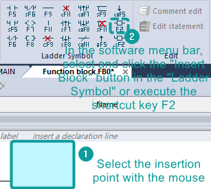
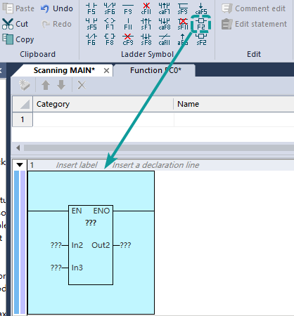
After the FB program is written, it needs to be instantiated and called for the function block to be used in the application program. In the upper menu of the software, click the "Insert Operation Block" button in the "Ladder Diagram Symbol" or execute the shortcut key F2.
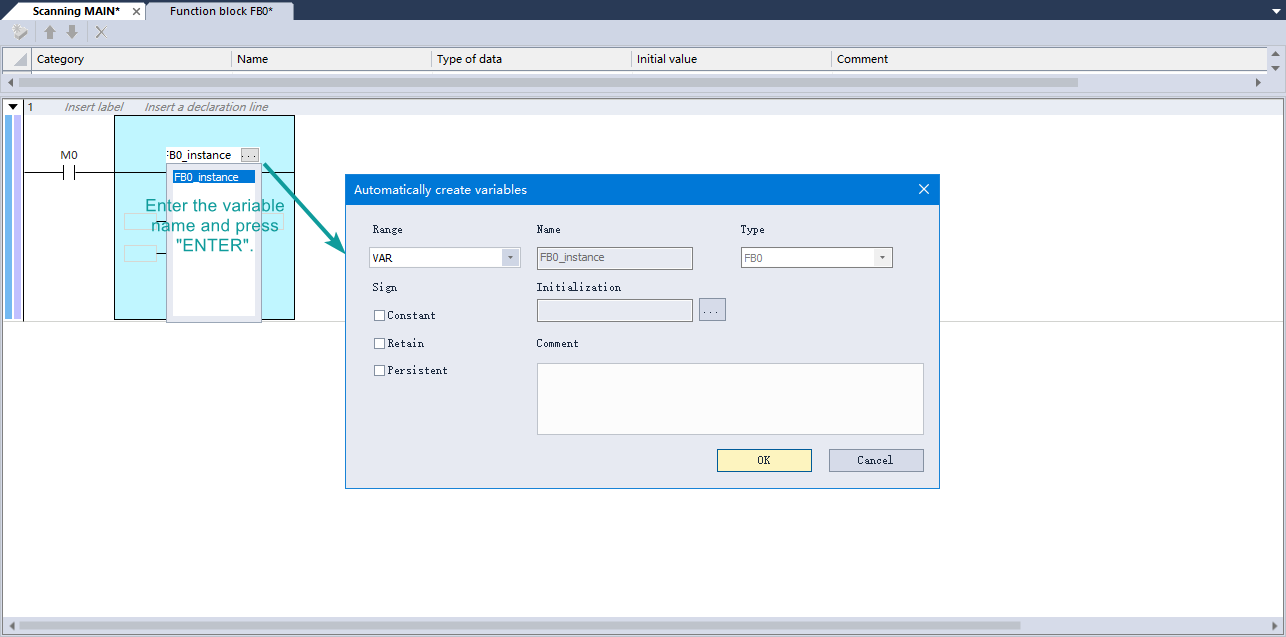
After inserting the function block, enter the name of the function block at the "???" inside the function block, and press the "Enter" key on the keyboard.

After entering the function block name, "???" will appear at the top of the function block instruction. Enter the variable name in "???", press the "Enter" key, and click "OK" in the pop-up dialog box to complete the instantiation of the function block.
Function (FC)
Function (FC) is an independently encapsulated program block. The program block can define input/output parameters type, and can also define non-static internal variables, so when a function is called with the same input parameters, the output result is the same. The important feature of a function is that its internal variables are static, without internal status storage; the same input parameters will get the same output, and it is the main difference between a function (FC) and a function block (FB). Function (FC) is often used in various mathematical operation functions as the basic algorithm unit, such as sin(x) and sqrt(x), which are typical function types.
The basic steps of using a function are: New Function -> Function Programming -> Call Function.
New Function
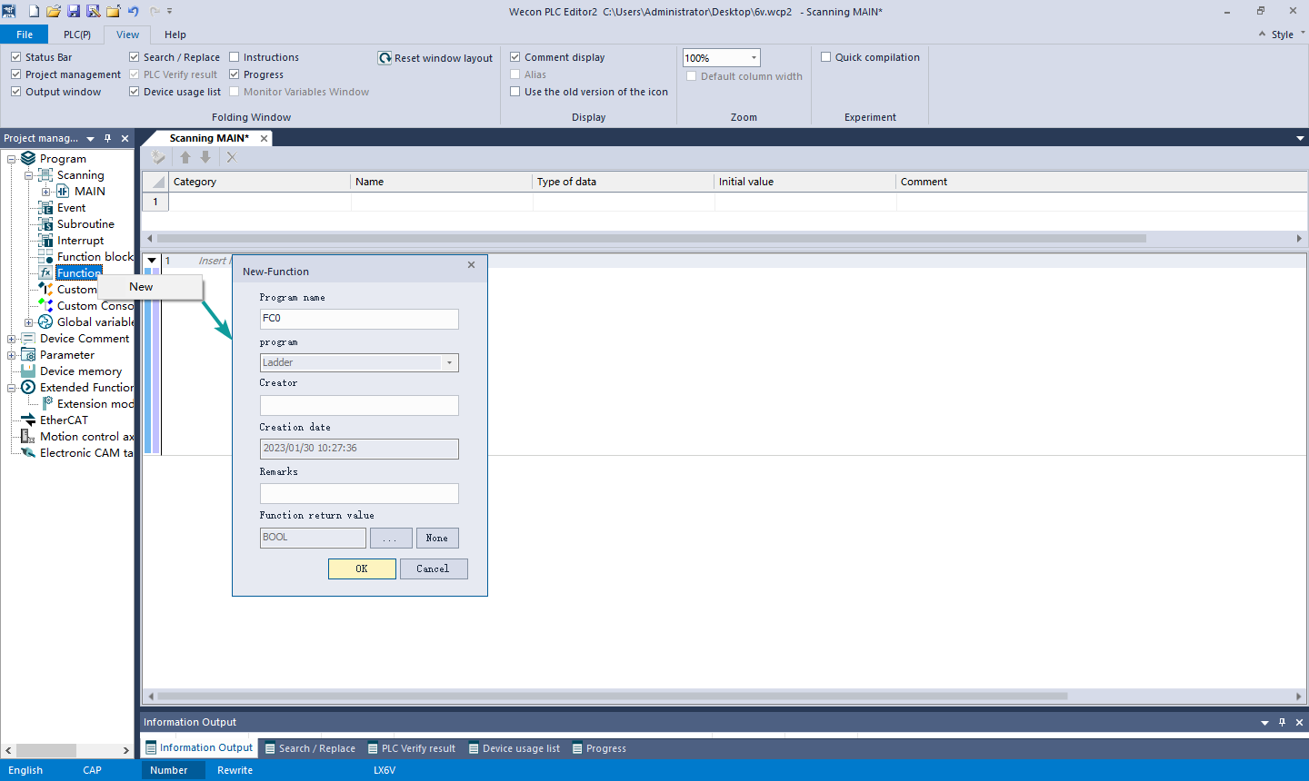
Create a new function via PLC Editor2 software.
Right-click the "Function Block" node in the project management area, select the New, enter the function name and other information in the pop-up dialog box, and click "OK" to complete the creation of the function.
Function Programming
The function only supports ladder diagram programming. Click the newly created function under the "Function" node to enter the function program editing interface. The function program editing interface is similar to that of function block.
- Compared with the variables of the function block, the function variables are non-retentive and cannot be saved after power-off;
- The function program uses the ladder diagram programming, and in the function program, functions can be called. The function itself can be called by other functions, function blocks and programs;
- In addition to variables, function programs can use global variables and devices;
- In the function program, instructions related to status or under multi-cycle execution cannot be used.
Example: Encapsulating OR with FC
Function calling
After the FC program is written, it can be used in function blocks/program.
Click the "Insert Operation Block" button in the "Ladder Diagram Symbol" and enter the function name.
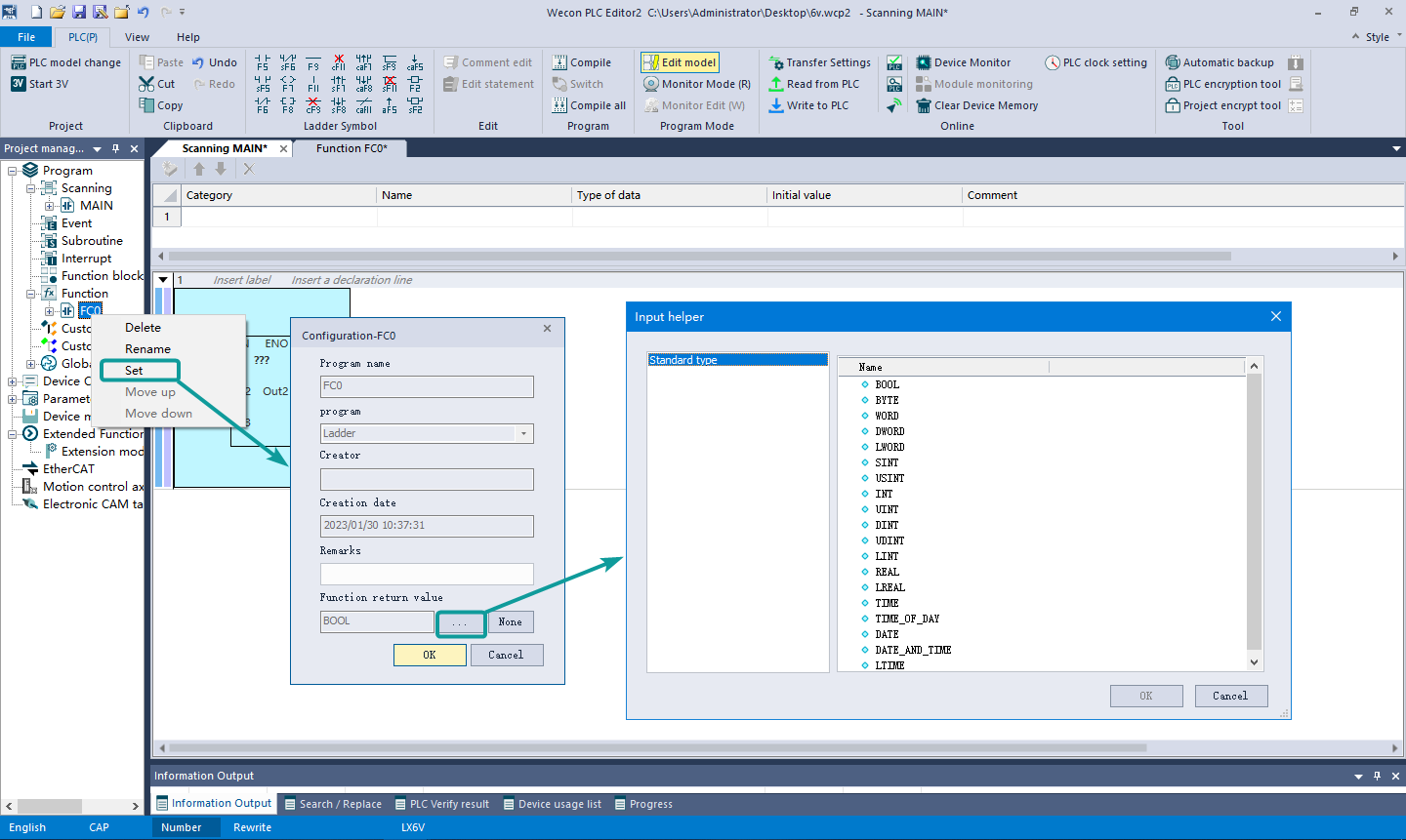
Function Return Value
Create a new function, or select the function in the project management and right-click to set, click "..." in the pop-up dialog box, and the input assistant dialog box will pop up, where user can select the data type of the return value.
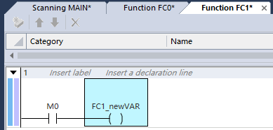
In the editing interface of the function module, the function name (FC1 in the figure below) can be programmed as the return value variable.
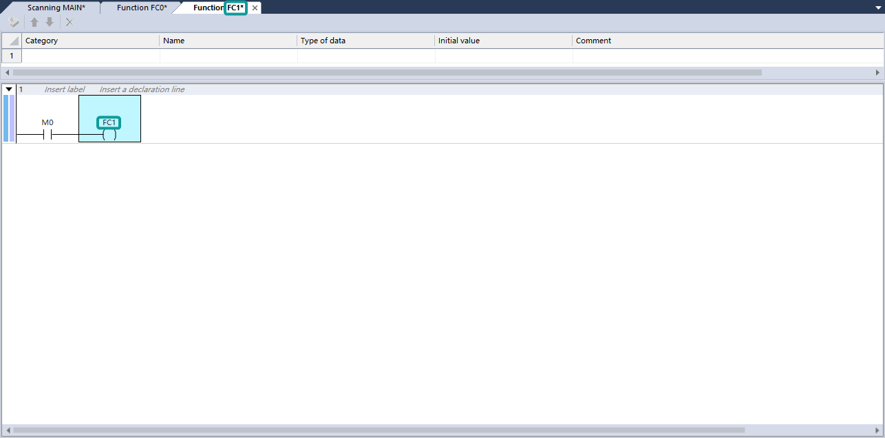
When the return value is a FB function block or a custom structure, the function name can be used as the instance name of the function block (FB), as the first-level variable to call the input and output variables under the FB. As shown in the figure below, the return value of FC1 is the FB1 function block, and the variable newVar of FB1 can be set through FC1.newVar.
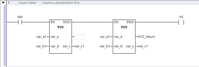
When using a custom function in the network view, there will be one more pin than the built-in function, and the pin description is empty, followed by a variable of the same data type as the function return value (FC0_return in the figure below), which is used to save the return value of the function (support blank).
Support Constant Input
Usage Rules
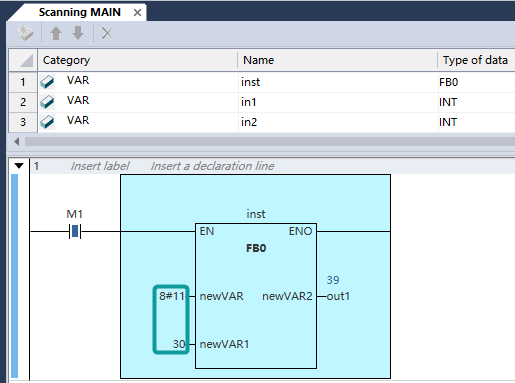
All operation block input pins (except for input output / output type) can be set to constant, constant type supports binary, octal and hexadecimal system. Integer constants are 64 bits.
Input Format
Floating point constants: -10.0, 1.2E+34
Decimal constants: 10, -10
Binary constants: 2#10111001
Octal constants: 28#0007, 8#1777
Hexadecimal constants: 16#FF, 16#FFFF, 16#FFFFFFFF
BOOL constants: TRUE and FALSE
Time constants: TIME#0ms, valid range: 0ms to 4294967295ms
TOD#0:0:0.001, valid range: 0:0:0 to 23:59:59
DATE#1970-1-1, valid range: 1970-01-01 to 2106-02-07
DT#1970-01-01:0:0:0, valid range: 1970-01-01:0:0:0 to 2106-02-07-06:28:15
LTIME#0ns, valid range: 0ns to (2^64-1)ns
Examples
The use of octal and decimal integers:
Support Input and Output Vacant
Usage Rules
① Built-in FC is not allowed to be vacant
② Input of the custom FC is not allowed to be vacant, but the output can be vacant;
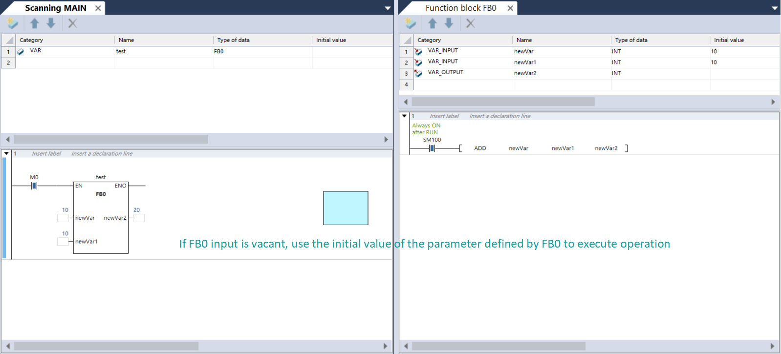
③ Custom FB input and output can be vacant;
④ Built-in FB can be vacant unless otherwise specified (for details, please refer to the description of the built-in FB in "LX6V Series PLC Programming Manual").
Examples
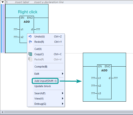
Support Extended Input
Input an operation block that supports extended input, select the operation block area, right-click --> select Add Input or use the shortcut key Shift+I to add additional input points, for example:
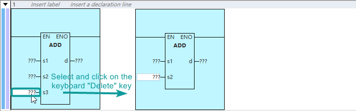
To delete the added input point, user can select the added input point and click the “Delete” to delete it.
Variable
Custom Variables
In PLC Editor2 programming, in addition to directly using addresses, such as M, D, S, X, Y and other devices for programming, user can also program in the form of [variables] without specific storage addresses, improve the convenience and reusability of code writing. The types of custom variables supported by this software are as follows:
| Data type | Keyword | Length (bits) | Value range |
|---|---|---|---|
| BOOL | BOOL | 1 | FALSE (0) or TRUE (1) |
| Byte | BYTE | 8 | 0 to 255 |
| Word | WORD | 16 | 0 to 65535 |
| Double Word | DWORD | 32 | 0 to 4294967295 |
| Long Word | LWORD | 64 | 0-(2^64-1) |
| Short Int | SINT | 8 | -128-127 |
| Unsigned Short Int | USINT | 8 | 0 to 255 |
| Int | INT | 16 | -32768 to 32767 |
| Unsigned Int | UINT | 16 | 0 to 65535 |
| Double Int | DINT | 32 | -2147483648 to 2147483647 |
| Unsigned Double Int | UDINT | 32 | 0 to 4294967295 |
| Long Int | LINT | 64 | -2^63 -(2^63-1) |
| Real Number | REAL | 32 | ±1.175495E-38 to ±3.402823E+38 |
| Long Real Number | LREAL | 64 | ±2.225073858507202E-308 to ±1.797693134862315E+308 |
| Time | TIME | 32 | 0ms - 4294967295ms |
| TIME_OF_DAY | 0:0:0 - 23:59:59 | ||
| DATE | 1970-01-01 - 2106-02-07 | ||
| DATE_AND_TIME | 1970-01-01 : 0 : 0 : 0 - 2106-02-07-06 : 28 : 15 | ||
| LTIME | 64 | 0ns - (2^64-1)ns |
Custom Variables
PLC Editor2 supports custom variables, users can directly use variable names in the program by defining global variables/local variables. The following rules shall be followed when defining global variable names:
① Can only be composed of "numbers, letters and underlines" and cannot start with "numbers";
② Cannot have the same name as "instruction, device, constant, standard data type";
③ Cannot have the same name as "program, function block, function, custom structure, custom union";
④ It cannot be keywords such as "struct, union, GVL";
⑤ It cannot start with "device + number";
⑥ The length should not exceed 32 characters.
Note: Variable names are case insensitive, i.e. A1 and a1 are the same variable.
Variable Data Types
Variable definition supports structures and arrays, and supported variable data type is shown in【Table 1 Custom variable types supported by this software】
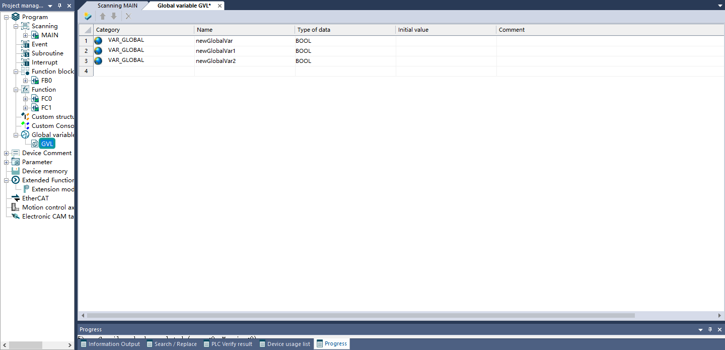
Define Global Variables
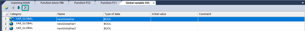
The "Program" -> "Global Variables" -> "GVL" table in the PLC Editor2 programming software project management column is used for variable management, which can realize the addition, deletion and editing of variables.
Add variable: Click the New button  at the top left of the global variable table to create a new global variable.
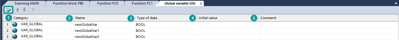
① Variable flags (constant and retain type) can be set in the category column, and the settings in the initial value column are only valid for non-retentive variables;
② Double-click the variable name column in the variable table to enter the custom variable name, and you can directly use the variable name to program when programming
③ Data type can choose the supported basic data types, arrays, structures, and unions (define the structure and union in advance). When selecting array as the data type, set the array variable type and interval length in the dialog box (the maximum length of the interval is [0,49]). When selecting a pre-defined structure or union, user can define the structure or union variable;
④ Double-click the initial value column to define the initial value for the variable, and the array, structure, and union can define the initial value of each element separately;
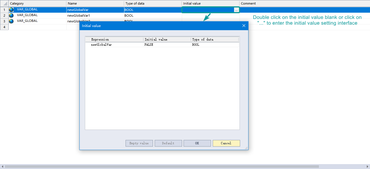
⑤ User can set the comment information of the variable in the comment column.
Delete variable: Click the delete button  on the top left of the global variable table to delete the selected variable.
Defining Local Variables
The difference between local variables and global variables is that local variables are defined in the program page/function block/function, and the scope is only in the defined window.
In the local variable window category, variables can be set as input variables, output variables, input and output variables, and temporary variables.
Defining Structure/Union
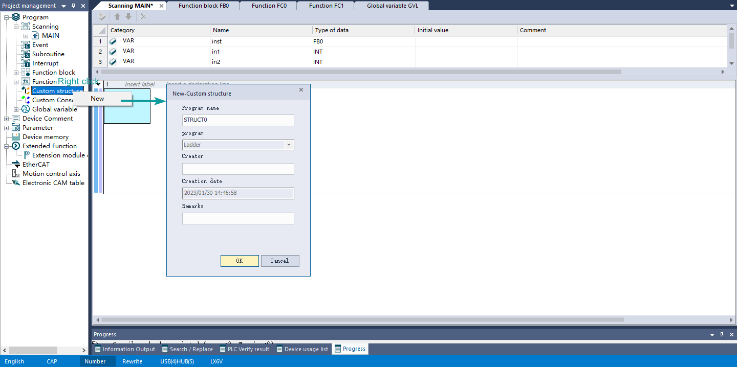
If you need to define a structure/union variable in the variable definition, you need to define the data structure of the structure/union in advance.
In "Program" -> right-click "Custom structure" / "Custom union" -> select "New" -> enter the program name in the pop-up dialog box -> click "OK", double-click the data structure name, open the data structure definition window to define the structure/union.
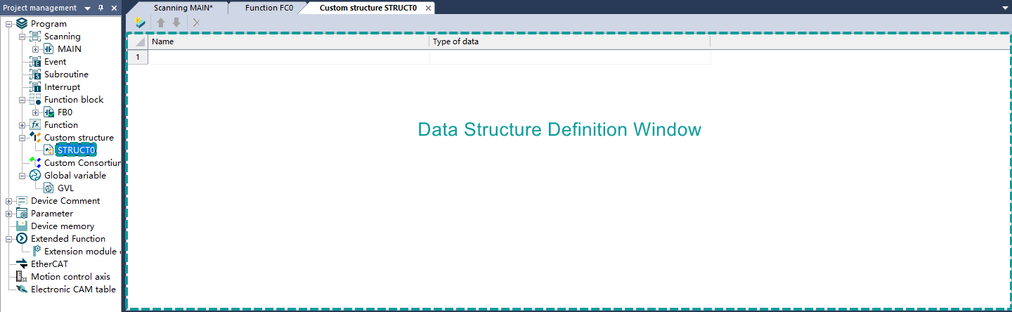
After establishing the structure/union and variable in the data structure definition window, user can select the structure in the data type of variable definition to define the structure/union variable. The operation steps are as follows:
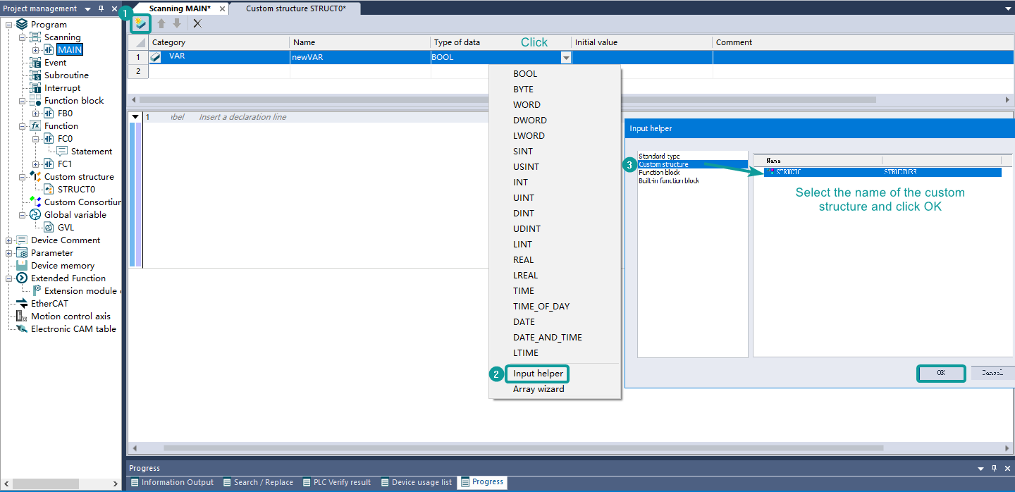
①Create a new Variable;
②Set the data type and select the input helper;
③Click the structure data type, select the name of the custom structure STRUCT0, and click "OK";
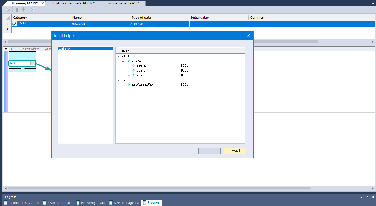
④Use the following methods to quote the defined structure data variable stu in the ladder diagram.
Method 1: Double-click the device variable name, click the button on the right, and select the variable in the variable tree information displayed in the pop-up window.
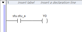
Method 2: Write the ladder diagram and directly input stu.stu_a.
The Usage of Variable
After the variable is defined, the variable name can be directly used for programming during programming, and there is no need to re-allocate the device.
- Directly perform variable programming operations;
- When using an array variable, use "[Number]" in programming to indicate the array element, and the number starts from 0;
- When using a structure variable, use "structure variable name. "Member variable" in programming to indicate a structure member;
- When using global variables, use "GVL. variable name" in programming to indicate a global variable.
Using Variables as Array Subscripts
Usage Rules
General rules for using variables as array subscripts: in the entire variable composition, at most one variable is used as a subscript, and the format is defined as array[index] or stu.var[index], wherein array means an array or a structure array, and index means a variable , stu represents the structure.
Basic Combination Types
1) array variable, as an array variable, only supports BOOL, BYTE, DATE, ATE_AND_TIME, DINT, DWORD, INT, LINT, LREAL, LTIME, LWORD, REAL, SINT, TIME, TIME_OF_DAY, LDINT, UINT, USINT, WORD, does not support pointer variables, etc.;
(2) index variable, as the variable of the array subscript, supports devices C, D, HSC, LC, R, SD, T, V, Z, and does not allow offsets; supports variable types BYTE, WORD, DWORD, LWORD, SINT, USINT, INT, UINT, DINT, UDINT, LINT; array nesting is not supported, such as array[index[5]];
(3) Structure arrays with double or multiple variables are not supported;
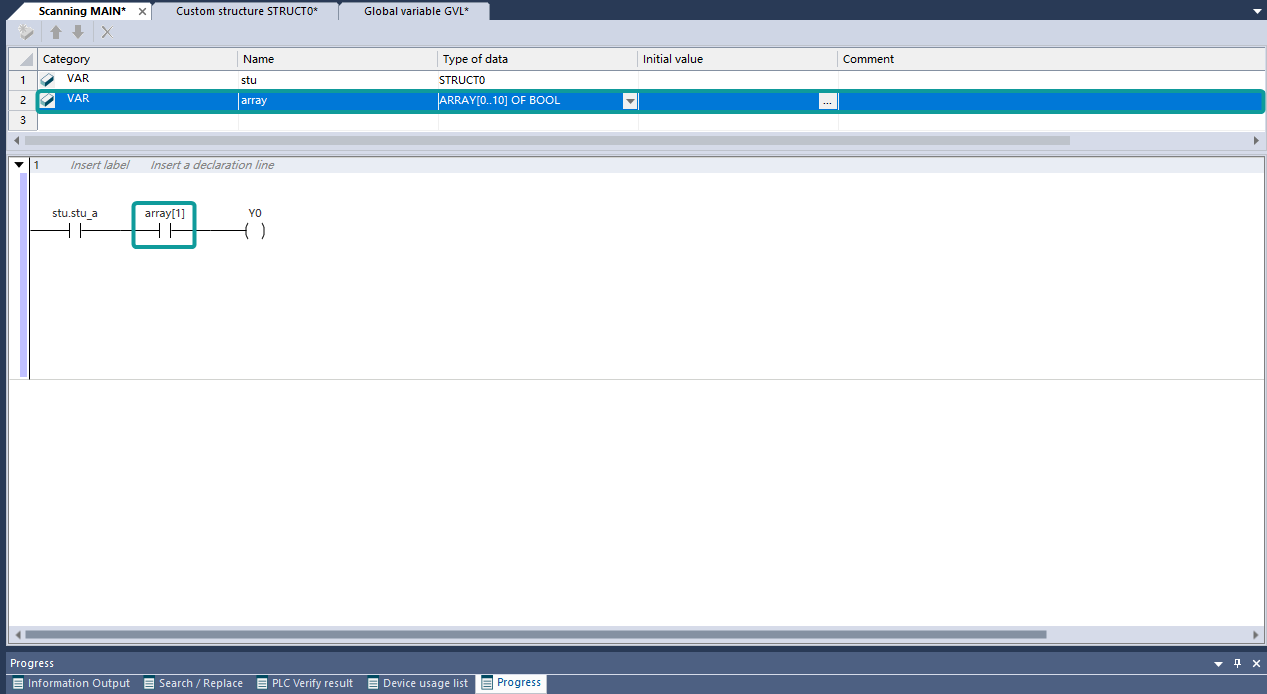
Examples
Create an array variable array[10] in the variable table, and declare array[1] for reference in the ladder diagram.
(4) Two-dimensional or multidimensional arrays array[index1][index2] are not supported.
If the array is defined in the global variable table, it is used as GVL.array[1] in the ladder diagram;
If the array is defined in a custom structure/union, it will be used as stu.array[1] in the ladder diagram.
Variable Binding Address
In programs or global variables, custom variable binding to soft element addresses is supported. After binding, the address of the custom variable is associated with the address of the soft element. The binding method involves entering a valid mapping address in the variable definition table. Only D or R soft elements can be mapped in program pages or global variables
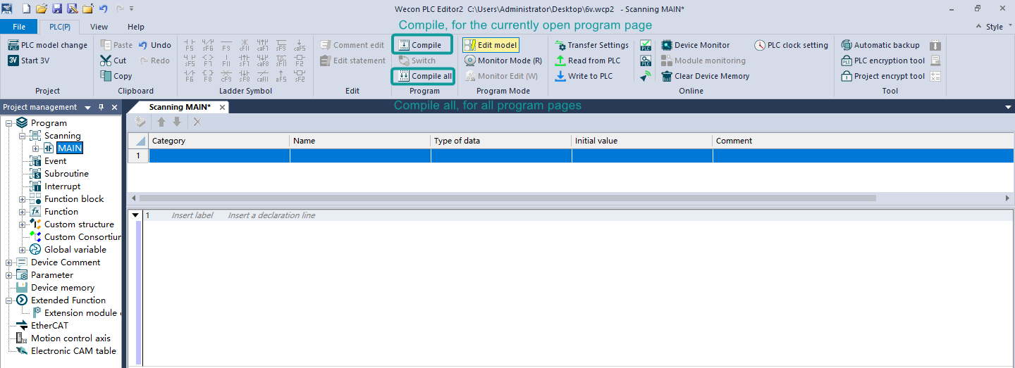
Compilation
The ladder diagram function remains consistent with the 5V function, including single-page compilation and full compilation, compilation result display, and double-clicking the compilation error report to jump to the compilation error problem. The current compilation will check the following errors:
(1) Single-page compilation will only compile the program of the current page, and full compilation will compile the programs of all pages in the project management.
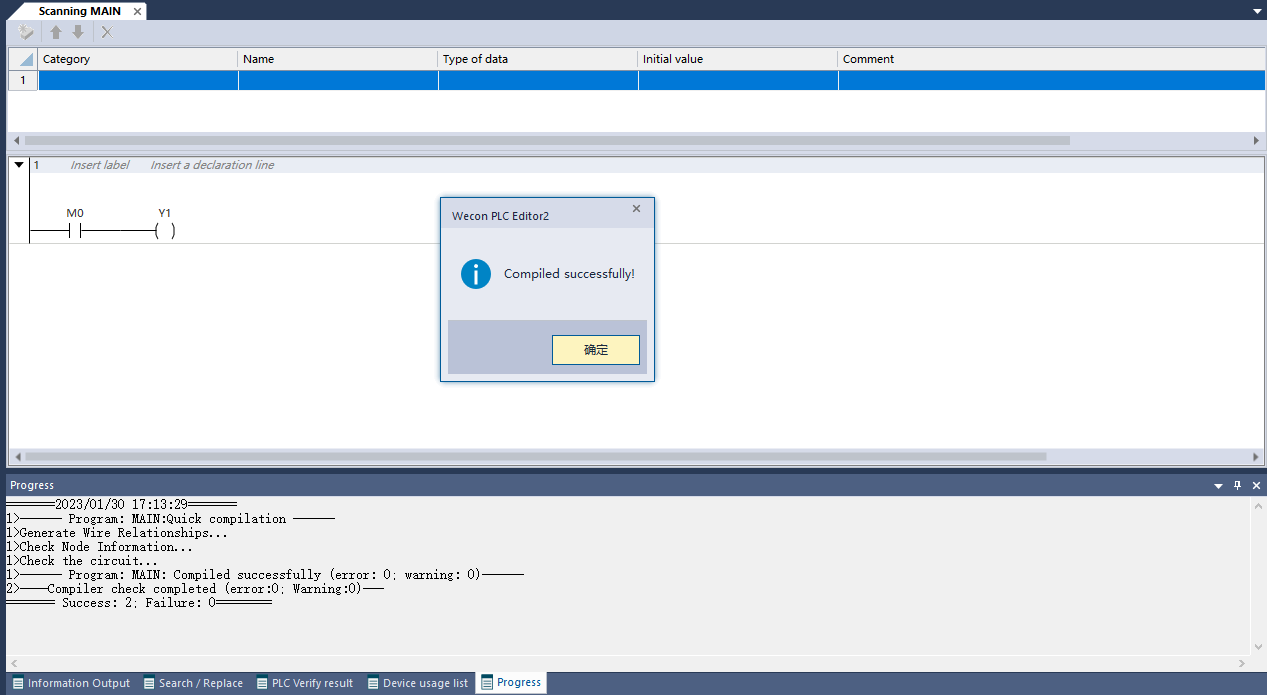
(2) Quick compilation
Check Quick Compilation in [Toolbar] --> [View] --> [Experiment], after enabling Quick Compilation, click Compile or Quick Compile to skip the compiled network and velocity up the compilation.
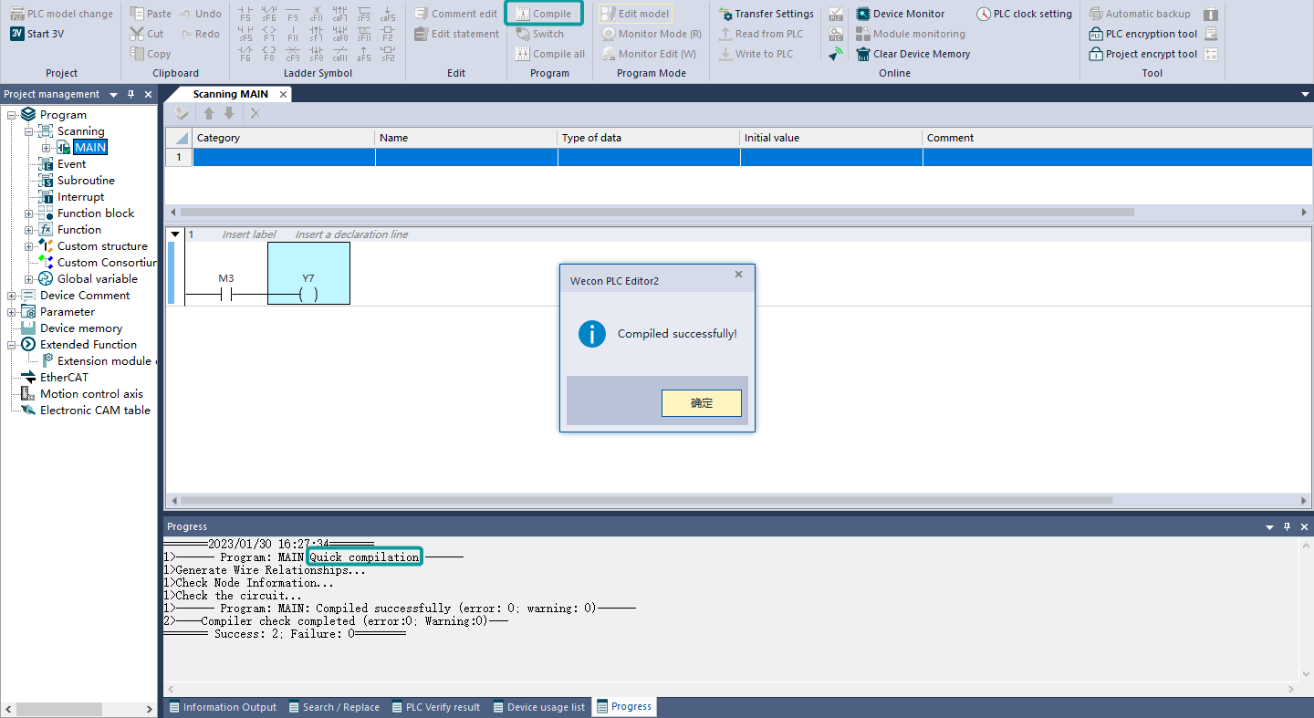
(3) Normal program without error
(4) Compilation error
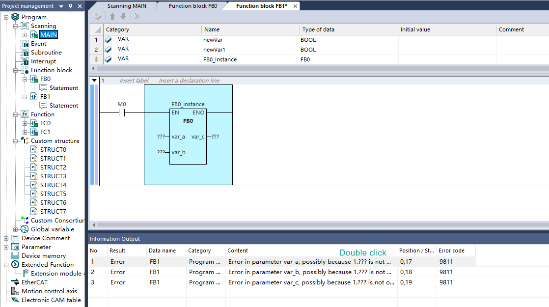
① Using undefined variables
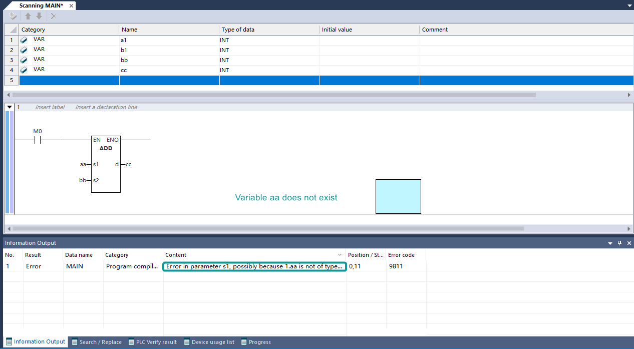
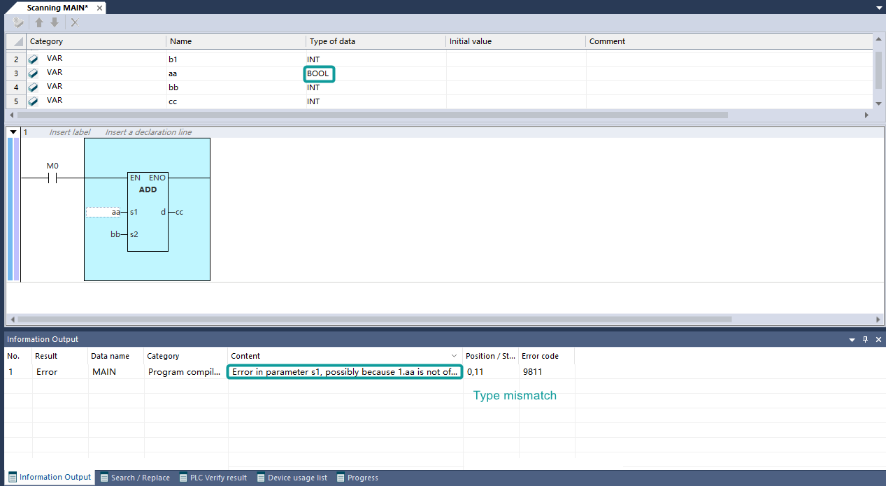
② The variable type of the function block call does not match
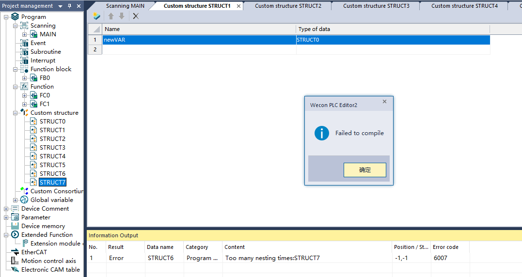
③ Too many layers of structure nesting (more than 6 layers)
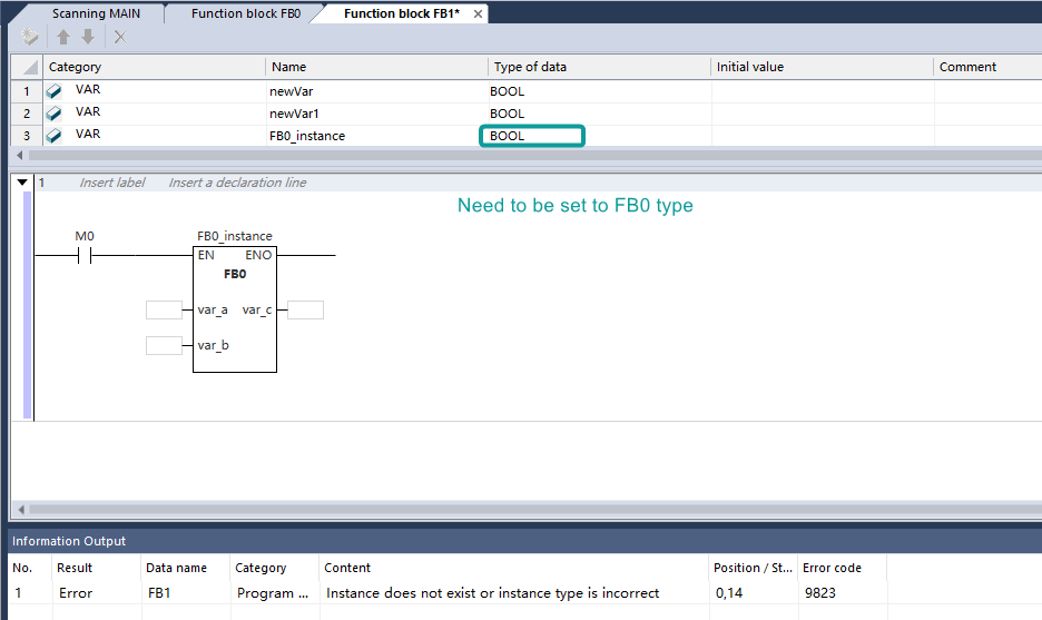
④ The instantiation type does not match
(5) Error jump: double-click the error message to jump to the error device for highlighting display.
Communication and Monitoring
Communication Test
(1) Function: The main purpose of the communication test is to check whether the project model created by the current PLC Editor2 software matches the model of the lower PLC and whether it can be connected for normal communication!
(2) Steps for usage:
① Open and run PLC Editor2;
② Move the mouse pointer to the [Online] module above the program panel;
③ Move the mouse pointer to the [Transfer Settings] button, and left-click the button;

④ Wait for the program to respond, and the [Communication Settings] dialog box will pop up;
⑤ The [Communication Settings] dialog box will pop up. If the [Detailed Settings] checkbox is not checked, select the specified port, and the panel is shown as below;
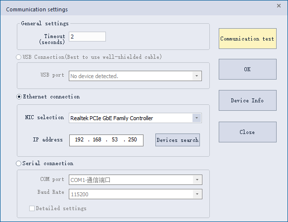
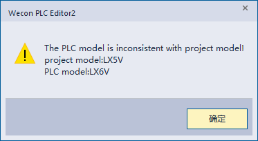
⑥ There are currently three channels that support communication with the PLC. Select the corresponding communication channel and configure the corresponding parameters (the use of each channel will be introduced below), and click the [Communication Test] button. If the PLC model is inconsistent with the project model, the following window will pop up.
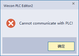
If there is a problem with the selected channel and the connection cannot be made, the following window will pop up.
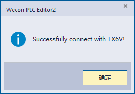
If it can communicate with PLC normally, the following window will pop up.
(3) Use of three communication channels
① USB connection: The USB channel of the 6V PLC uses the USB-C (Type-c) interface, which only supports USB-C cable for connection. If the current PC uses a USB-C cable to connect to the USB-C port of the PLC, the software will select [USB connection] button by default.

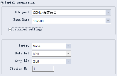
② Serial port connection: The serial port channel of the 6V PLC device uses the RS485 interface. After the PC is connected to the PLC using the 485 cable, you can select the required baud rate through the drop-down box of [Baud Rate], and check the [Detailed Settings] button to configure the corresponding serial port parameters. (Note: The default parameters of the serial port connection in the new 6V project are also the default parameters of the 6V PLC 485 serial port.)
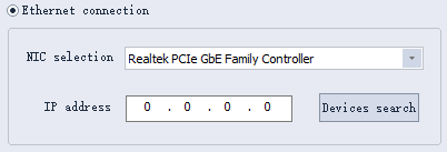
③ Ethernet configuration: 6V PLC supports communication via Ethernet connection. Plug the Ethernet interface on the 6V PLC device into the network cable to support Ethernet communication! Click the [NIC selection] drop-down box to select the network card, and enter the IP address of the PLC device in the [IP Address] input box to start the communication connection.
If user do not know the IP address of the PLC, first upload the parameter information through the USB-C or serial port, and then view the Ethernet-related information configuration on the parameter interface; or user can click the [Device Search] button to search for the PLC devices connected in the same network segment.
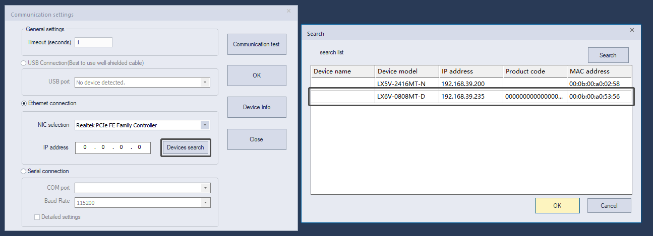
Device search: used to search for all PLCs that support Ethernet functions in the network segment that match the subnet mask. The network segment that matches the subnet mask refers to following circumstance: if the IP of the machine is 192.168.56.237 and the subnet mask is 255.255.255.0, then the PLC in the network segment of 192.168.56 is searched; if the IP of the machine is 172.16.56.1, the subnet mask is 255.255.0.0, then the PLC in the network segment of 172.16 is searched; If the IP of the machine is 10.244.56.9 and the subnet mask is 255.0.0.0, then the PLC in the network segment of 10 is searched.
Use of device search: Click [Device Search] to pop up the search interface, click the search button to search for devices in the relevant network segment. Select the device information line to be connected, and then click OK. The selected IP address information will be automatically filled in IP address input box of [Communication Settings] interface.
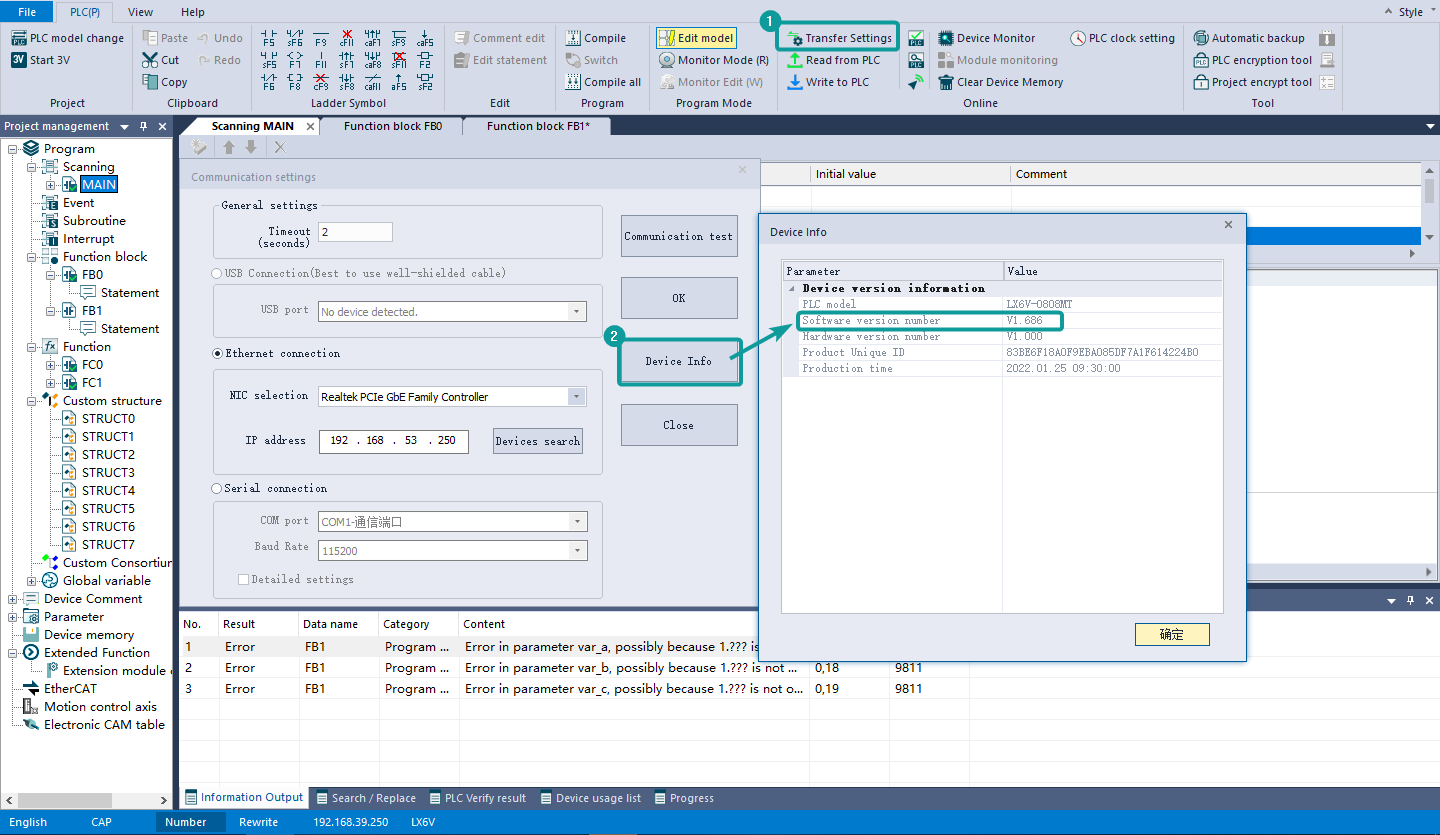
(4) Device Info
① Function: It is used to view the relevant information of the connected PLC, such as PLC model, production date and other relevant information.
② Use steps: After establishing a communication connection with the PLC device through the above steps, user can click the [Device Information] button to pop up the corresponding device information interface.
Ladder Diagram Monitoring
Function:Monitor the value of the devices and FB/FC parameters on the ladder diagram, modify and debug the program.
Steps:
① Connect to the PLC and switch to monitoring mode;
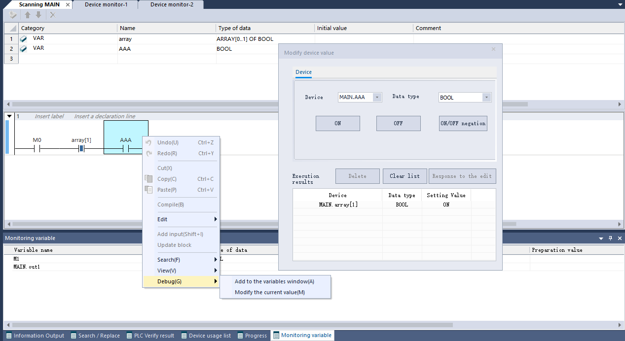
② Modification of device value: modify the used device value in the pop-up window for modifying device value.
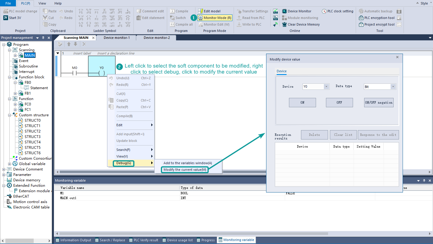
The window for modifying device values supports modification of variables.
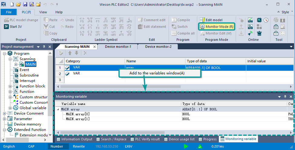
③ Variable value monitoring: In the monitoring mode, in the local variable table window, select a variable, right-click the menu, click “Add to variable window” to add the variable to the monitoring variable window below, and then monitor the variable value.
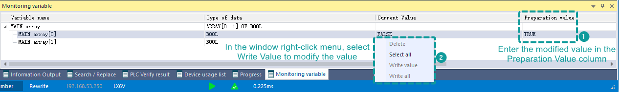
Variable value modification: after adding the variable to the monitoring variable window, modify the value in the following steps.
Search and Replace
Search/Replace: Similar to the search and replace function of OFFICE, it can locate the data block specified by the user in a large amount of data, or perform batch addition, deletion, modification and query, which can greatly improve efficiency.
Usage method: Open the main program, after creating a new project, click [Ctrl] + [F] on the keyboard to pop up the search/replace interface, as shown in the figure below.
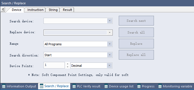
Buttons are divided into four categories: device, instruction, string and result, as shown in the figure above. Click any one to switch to the corresponding operation interface.
Device: The following contents can be searched/replaced.
① All devices
② Legal custom variables, including array type variables and multi-level variables
③ Real numbers in scientific notation format
④ Strings with quotation marks
⑤ Customize the name of FC
⑥ FB instance names
Instruction: The following contents can be searched/replaced.
①All instructions
②Built-in FB/FC
③ Custom FB/FC
Device Usage List
The device usage list mainly displays the specified type of devices. You could check the usage, and the corresponding comment of the device. Devices used in program pages such as scans, events, subroutines, interrupts, function blocks, and functions can be displayed.
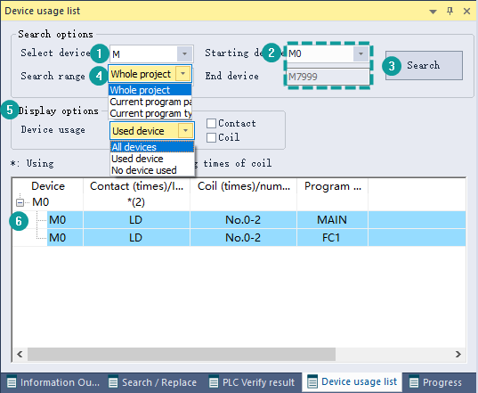
Instructions for device usage list:
① Device selection drop-down box: select a device, search and display the usage of the corresponding type of device (starting from serial number 0);
② Starting device drop-down box: You can input the full name or serial number of the starting device, press the Enter key or click the "Search" button to search for the usage of specified type of device (starting from the initial button, search and display the serial number). Record the search record in the drop-down box. After selecting the record, you could perform the search again.

③Search button: perform a search operation. When the starting device is empty, it will prompt to input a device.
④ Search range: specify the device search range;
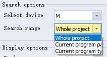
Whole project: for all program pages of the current project;
Current program page: Search only for the currently active program page.
Current program type: Only for all program pages of the same type in the currently activated program page. (Program page types are divided into: scan, event, subroutine, interrupt, function block, function.)
⑤ Display options
All devices: After selecting, search and display all devices of this type;
Used devices: After selecting, search and display the used devices of this type according to the contact and coil options;
Neither the contact nor the coil is selected, and all the devices of this type that have been used in the program are displayed;
Select the contact (coil) to display the device of this type as the contact (coil) in the program.
Select both contacts and coils, display the devices of this type that are used as contacts and coils in the program.
Unused devices: After selecting, display all the devices of this type that are not used in the program.
⑥ Expand and close the sub-item of the device usage list, including the instruction, step number, type and other information of the device in the program. Double-click the content of the subitem to locate the corresponding position in the program.
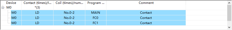
Device comment: (the background color is white) displays the comment of the device.
Expansion Module
Description
The expansion module is used to expand the functions of the PLC. It is easy to install, and the number of modules can be increased or decreased. The types of modules include IO modules, analog quantities, communication modules, etc. (LX6V series PLC currently only supports IO modules). The upper computer can download the module parameter information to the expansion module through the function of the expansion module configuration.
Use of Functions
(1) Expansion module configuration interface display
[Expansion module configuration] is located under the [Extended function] note of project management, double-click to open the expansion module configuration interface!
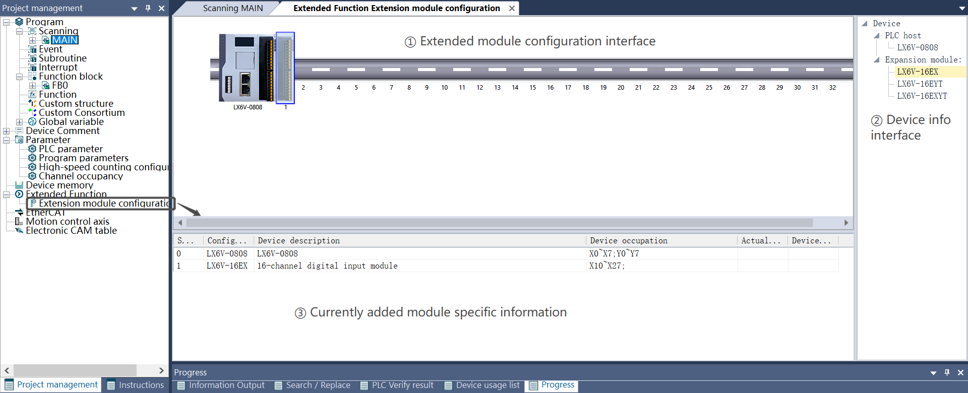
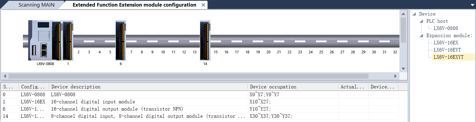
(2) Functions of each part of the expansion module configuration interface
① Device information interface: the information under the PLC host node stores the host points supported by the current model. User can manually select or switch different host points. The maximum number of expansion modules supported by PLC with different points is different; the information under the expansion module node stores the expansion module models supported by the current model, and user can choose to add modules of the corresponding model;
② Display interface for the specific information of the currently added module: the slot number shows the position of the current module configuration (the 0th position defaults to display the PLC information with the corresponding points); the configuration device name shows the model of the expansion module; the equipment description shows the brief introduction of the expansion module; the device occupation shows the device range mapped by the current module (note: when adding a module, an unused address will be allocated in order by default); the actual installation type shows the actual expansion module model at the corresponding position of the lower computer (note: this will only display the actual expansion module model at the corresponding position in the monitoring mode); the device version number shows the actual expansion module version number of the corresponding position of the lower computer (note: only in the monitoring mode will the actual expansion module model of the corresponding position be displayed);
③ Configuration interface of expansion module: configure the extension module in a visual way, which makes the effect more intuitive! Operations such as moving the position of the expansion module, deleting the expansion module, and exchanging the position of the expansion module improve the efficiency of human-machine interaction.
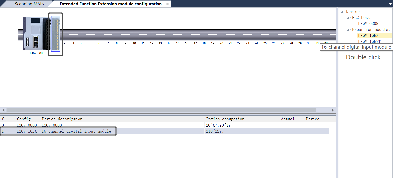
(3) Basic operation of expansion module configuration
① Add an expansion module: first select the corresponding PLC host points, then select the corresponding expansion module model and double-click, the picture of the corresponding configuration expansion module will appear in the configurationinterface, and the corresponding device information will also appear in the lower left corner of the interface, then the extension module is added successfully.
When adding an expansion module, the system will assign an unused device address for the IO mapping of the expansion module by default, and the user can also enter the configuration interface to manually modify the range of the IO mapping.
② User can drag the position of the expansion module, and drag the expansion module to different machine slot positions.
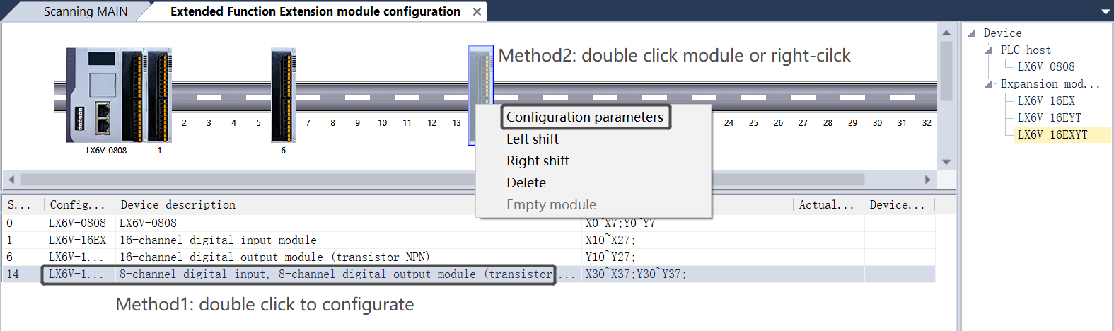
③ Configure expansion module parameters: method 1: user can right-click on the corresponding expansion module in the configuration interface to select configuration parameters or double-click to directly pop up the parameter configuration interface; method 2: in the configuration interface of the expansion module, double-click the corresponding module configuration line to pop up the parameter configuration interface.
④ The information to be configured is different for different expansion module models, but a default configuration information will be generated when an expansion module is added. Currently there are mainly 3 configuration interfaces.
- Device info: mainly used to store some basic information of the current expansion module.

- I/O mapping interface: It is mainly used to allocate the input and output mapping corresponding to the expansion module. Enter a starting device in the edit box, and a continuous address will be automatically assigned. After clicking OK, the corresponding I/O mapping configuration will be saved. (Note: Clicking the reset button will reassign unused addresses according to the order of addresses.)

Note 1: Software that has already been mapped is not allowed to be re-mapped, otherwise an error will be reported when the configuration is saved.
Note 2: Unsupported I/O mapping address is not allowed to be assigned. (For the address type of I/O mapping supported by the expansion module, please refer to the manual of the corresponding expansion module model.)
Note 3: For device of octal type X and Y, the address of I/O mapping must be X0~X7, X10~X17(consecutive 8-multiple addresses), and discontinuous addresses such as X1~X10, X2~X11 are not allowed.
- Module configuration interface: mainly used to configure parameters information of the module. (For the parameter information to be configured by the expansion module, please refer to the manual of the corresponding expansion module model.)

(4) After the configuration of the expansion module interface is completed, the corresponding module configuration information can be downloaded to the PLC through the download interface. The PLC expansion module configuration can also be uploaded through the configuration upload interface.

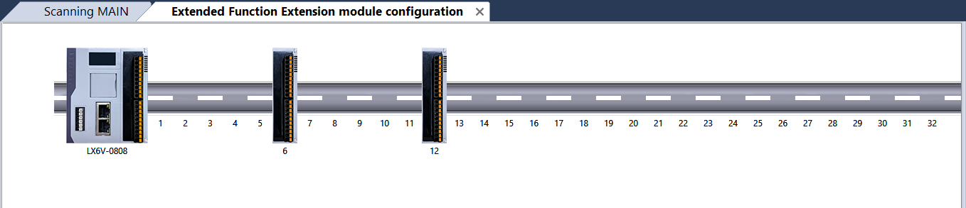
Note 1: When downloading the configuration of the extension module, the configuration of the module must be continuous in order to ensure normal download. As shown in following left figure, if the expansion module is placed at following intervals, the configuration cannot be downloaded normally. The module position shall be adjusted and the configuration can be downloaded normally when the modules are continuously arranged.

Note 2: When downloading the extension module configuration, the configuration host points must be the same as the actual PLC host points to ensure normal download.
(5) After the download is completed, enter the monitoring mode. On the display interface of the specific information of the currently added modules, the actual installation type column and the device version number column will display the corresponding model and version number according to the type of module actually connected to the corresponding position of the PLC.

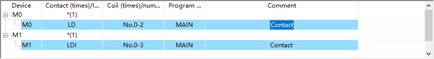
(6) User can view the occupied address of the device configured by the expansion module through the device usage list interface.


EtherCAT
Description
EtherCAT is an open industrial field technology based on Ethernet, which has the characteristics of short communication refresh cycle, small synchronization jitter, and low hardware cost.
Master Station Configuration
Double-click the EtherCAT node of the project management tree to pop up the EtherCAT configuration, modify the configuration and save it.

Importing and Adding Slaves
Importing Configurations
Right-click the EtherCAT node in the project management tree, click New, click the Import button in the pop-up Add Slave window, and select the EtherCAT xml file of the corresponding manufacturer to import.

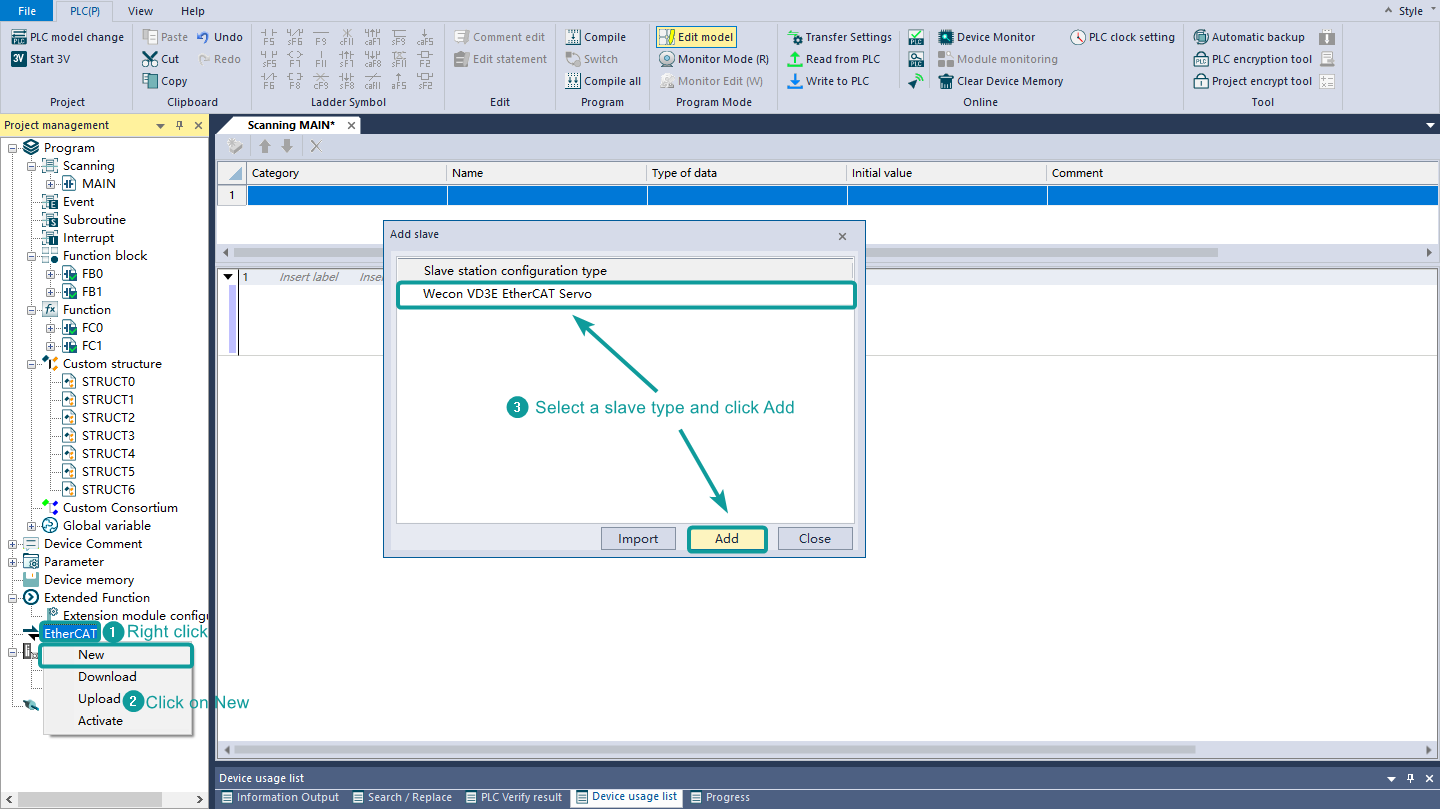
Adding a Slave
Right-click the EtherCAT node in the project management tree, click New, select a slave type and click Add, a new slave node will be added to the EtherCAT node in the project management tree, and click Close to end the operation of adding a slave.

Slave Configuration
Delete
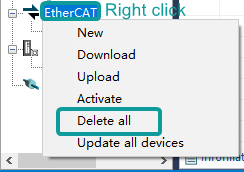
① Right-click the EtherCAT node, select Delete All, and delete all currently created slave station configurations.
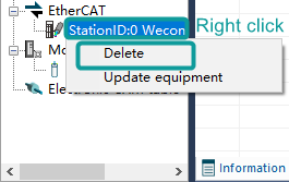
② Right-click the slave station under the EtherCAT node, select Delete, and delete the current slave station configuration.
Updating Devices
① Right-click the EtherCAT node and select Update All Devices to update the configuration information of the current EtherCAT node to the newly imported EtherCAT configuration file information.
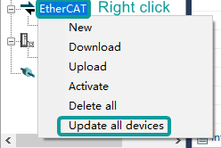

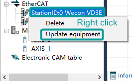
② Right-click the slave station under the EtherCAT node, select Update equipment, and update the configuration information of the corresponding slave station node to the newly imported EtherCAT configuration file information.
Slave Parameters
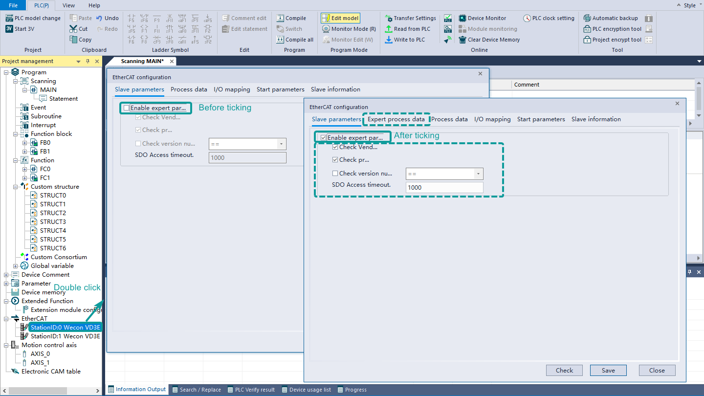
Double-click the slave station under the EtherCAT node to pop up the EtherCAT configuration dialog box. In the slave station parameter interface, check the enable expert parameter to use the expert process data interface and the check box and edit box below.
- Check Vendor ID: check whether the downloaded slave configuration is consistent with the vendor ID of the slave connected to the PLC during activation;
- Check product ID: check whether the downloaded slave configuration is consistent with the product ID of the slave connected to the PLC during activation;
- Check the version number: check whether the version number is consistent during activation;
- SDO access timeout: set the SDO access time.
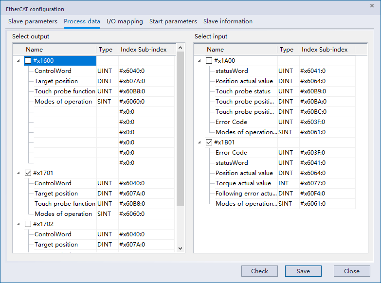
Expert Parameters
- Select ① the synchronization manager table area, select input and output, and ② the PDO allocation table area will be updated with the PDO allocation list corresponding to the output or input of the synchronization manager;
- Check or uncheck to enable the ②PDO allocation list area, which will be fed back to the ③PDO list;
- Select the checked row in the ③PDO list, and the contents of the ④PDO content table will be updated;
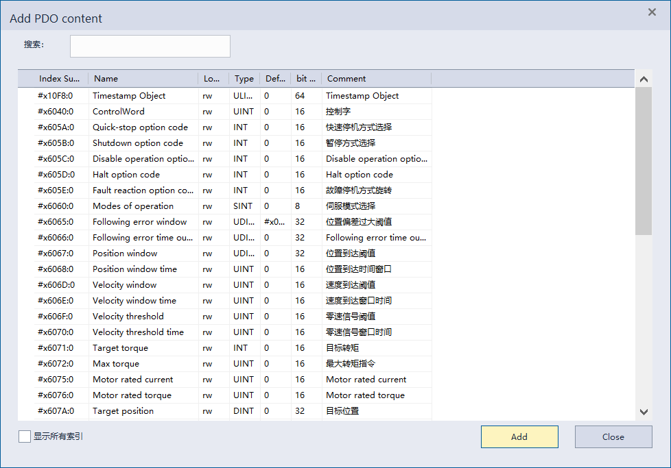
- In the ④PDO content table, right-click the menu and select Add or click the ⑤Add button, select the content to be added in the Add PDO content interface, and then click Add;
- After selecting the content to be deleted in the ④PDO content table, right-click the menu and select Delete or directly click the ⑥Delete button to delete.
Process Data
Except that the process data interface cannot customize the PDO content, other functions are basically the same as the expert process parameters.
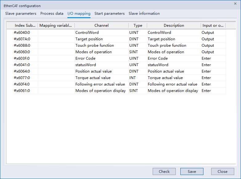
I/O Mapping
For the PDO content set by the process parameters, user can select devices or variables for mapping.
Start-up Parameters
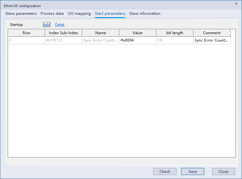
① Add
Right-click the menu to select Add or click the Add button directly to enter the interface for adding startup parameters, select the corresponding item, and add startup parameters.
② Delete
After selecting the parameter content to be deleted, right-click the menu and select delete or directly click the delete button to delete.
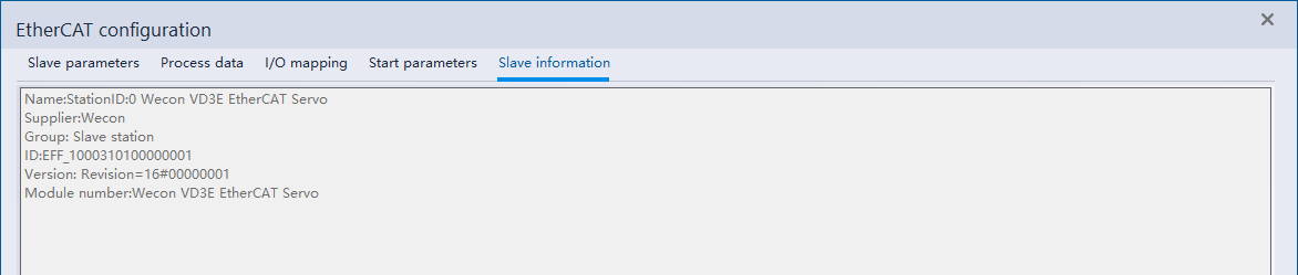
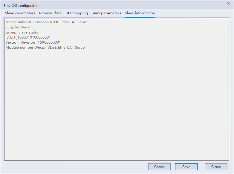
Slave Information
Display slave information.
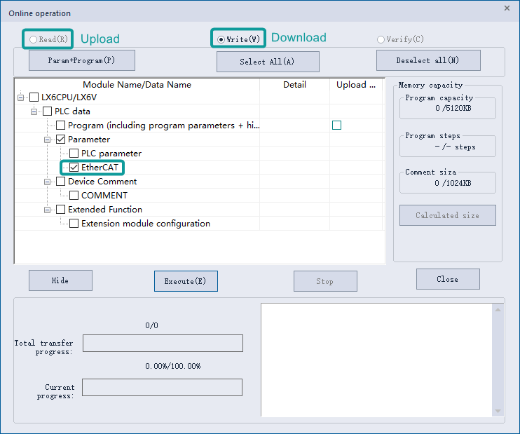
Activate Download and Upload
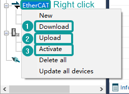
① Download
Select EtherCAT node in the project management tree and right-click, and select Download EtherCAT configuration or upload it by using PLC download interface.
②Upload
Select EtherCAT node in the project management tree and right-click, and select Upload EtherCAT configuration or upload it by using PLC upload interface.
③Activate
Select EtherCAT node in the project management tree and right-click, and select Activate EtherCAT configuration. (Note: The servo device connected to the PLC needs to correspond to the downloaded configuration slave during activation, otherwise an activation error will occur.)
Motion Control
Description
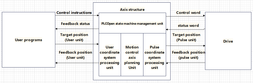
In the LX6V motion control system, the object of motion control is called "logic axis". Axis is the bridge between mapped Motion Control function blocks and servo drives. The logic axis of LX6V is used to control the EtherCAT bus driver conforming to the CIA402 protocol, and can also be configured as local high-velocity pulse output and input (the current version of high-velocity pulse input and output is not yet supported).
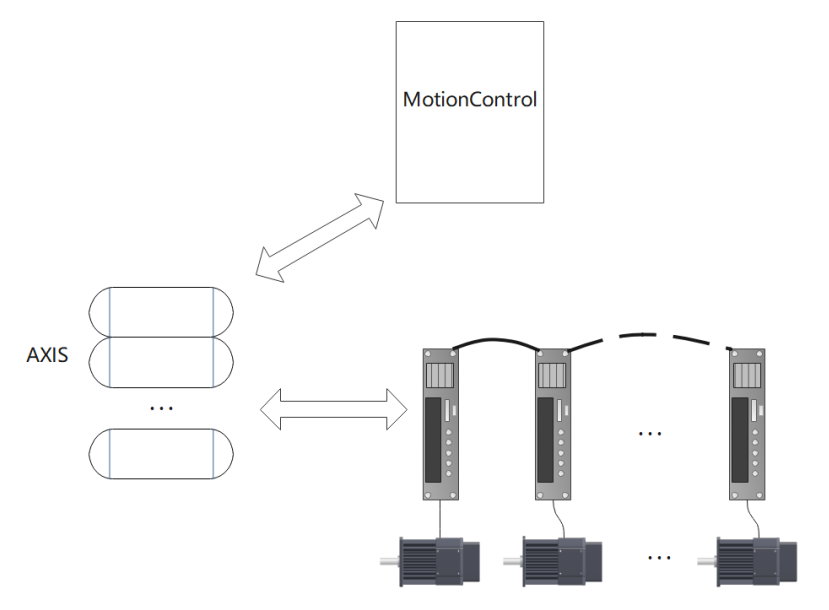
Inside the PLC, the basic composition and processing logic of the logic axis are as follows:
Motion Control Axis Operation
New
Method 1: Creating a new EtherCAT slave station will automatically create a motion control axis. And the newly created motion control axis will be bound to the newly created EtherCAT slave station.
Method 2: Create a new motion control axis directly. The output device of the newly created motion control axis in this way is unallocated by default.
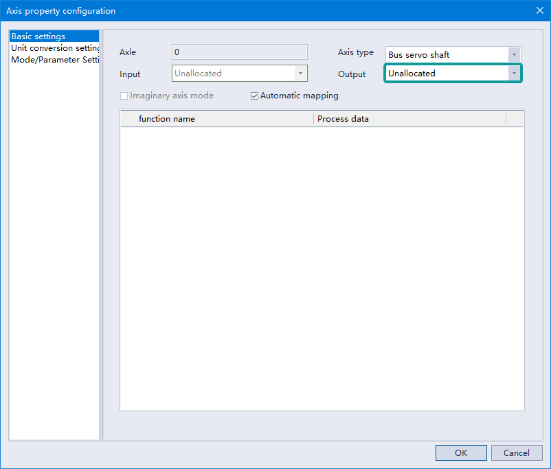
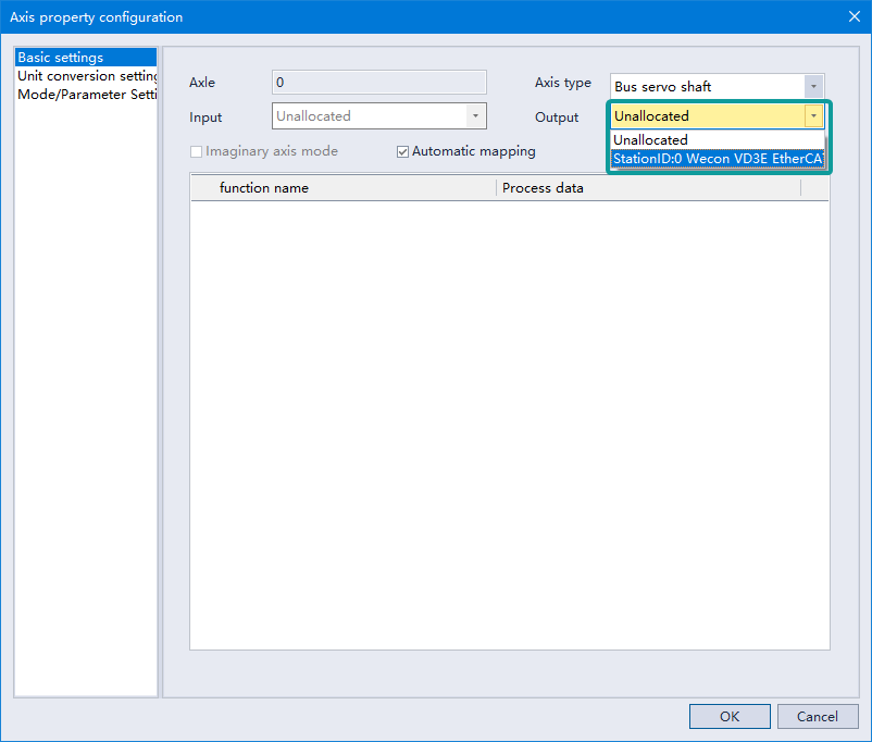
Setting up Output Devices
Only the idle EtherCAT slave axis can be selected in the drop-down box, click OK after selection, other axes cannot select the output device.
Upload and Download
Follow the EtherCAT upload and download, there is no separate download and upload interface.
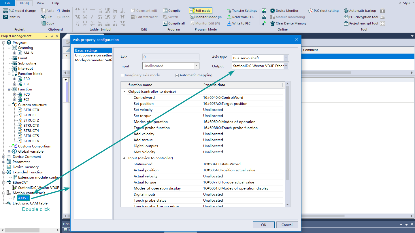
Configuration Interface
Basic Settings
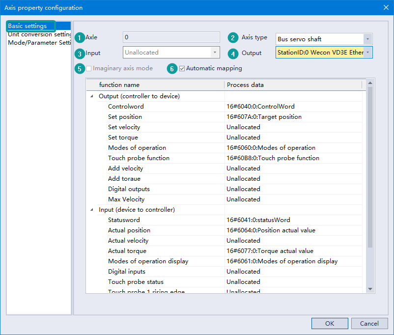
① Axis number: automatically generated by the system and unique. The current software version only supports binding motion control function blocks through axis numbers;
② Axis type: the current version only supports the motion control function of the bus servo axis;
③ Input device: the current version does not support;
④ Output device: used to select and bind the physical servo axis on the EtherCAT bus;
⑤ Virtual axis mode: provide virtual axis mode to support use in the mode without physical axis, for debugging purposes or other advanced programming methods;
⑥ Automatic mapping: TxPDO and RxPDO in the bound EtherCAT bus physical servo axis will be automatically mapped to the output and input supported by motion control.
Unit Conversion Settings
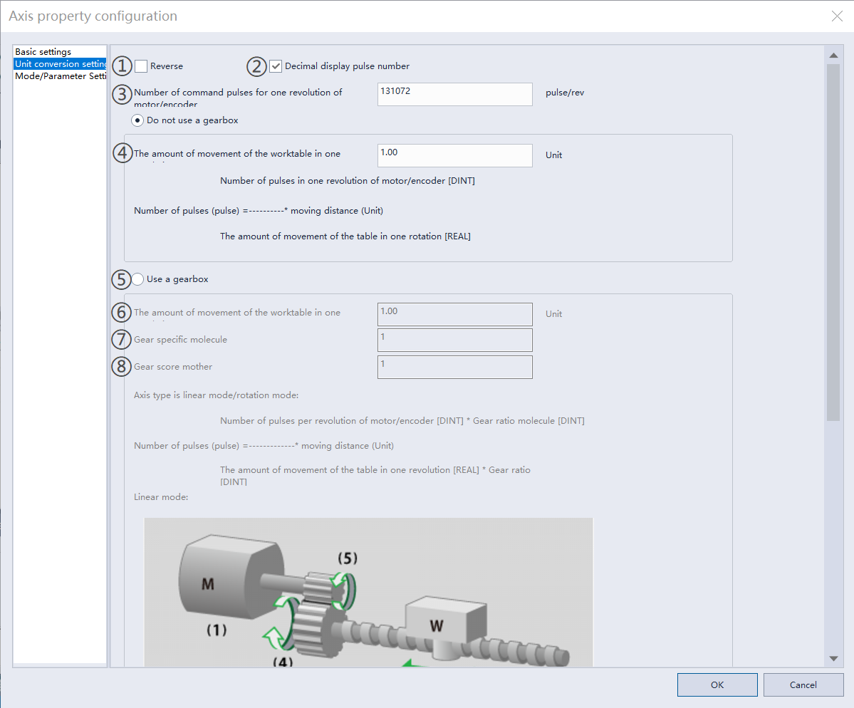
① Reverse: opposite to the set motor rotation direction (for example: after selecting reverse option, set the target position as positive, and the motor will run in the reverse direction);
② Decimal display of pulse number: display the pulse number value in decimal system;
③ Number of command pulses for one revolution of the motor/encoder: the real encoder resolution of the bound servo drive;
④ The amount of movement of the worktable in one rotation: this is the relationship amount between the user unit and the pulse unit;

Example: The encoder resolution of the user's servo axis is 17 bits, and the set pulse number is 131072. At this time, set the movement amount of the worktable to rotate one circle as 1 user unit. When using the motion control function and the target position is 1 (Unit), the number of pulses received by the servo drive is 131072 when the target position is reached, that is, the servo makes one revolution. When the target velocity is set to 5 (Unit)/s, it means that the servo operating velocity in the constant velocity section is 5 revolutions/s.
⑤Enabling gearboxes;
⑥ The amount of movement of the worktable in one rotation: set the movement amount of the worktable for one circle
⑦⑧ are respectively (5) and (6) in the linear model.
Mode/Parameter Setting
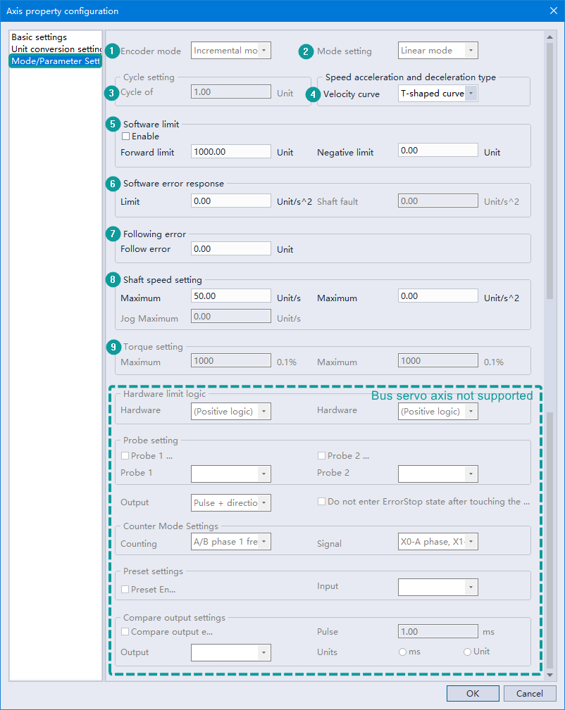
① Encoder mode: Incremental mode and absolute mode are optional. Under the current software settings, only incremental mode is supported;
② Mode setting: linear mode and rotary mode are optional. The current software only supports linear mode;
③ Cycle setting: cannot be modified. controlled by the EtherCAT task cycle;
④ Velocity acceleration and deceleration type: currently supports S-curve and T-curve. Among them, the S-shaped curve is a 7-segment and 5-segment adaptive curve;
⑤ Software limit: It is optional to enable software limit. When it is turned on, periodically check whether the target position exceeds the limit in the motion control function;
⑥ Software error response: limit deceleration and axis fault deceleration can be set, currently only support limit deceleration;
⑦ Tracking error: You can set the maximum tracking error threshold allowed by the system (user unit);
⑧ Axis velocity setting: the axis velocity limit function is enabled by default. User can set the maximum velocity (Vel), maximum acceleration (Jerk), and jog maximum velocity (JogVel) respectively;
⑨ Torque setting: set the limit of positive torque and negative torque. The motion control function will check whether the torque value fed back by the servo exceeds the corresponding limit every cycle, and if it exceeds, an error will be reported;
Hardware limit logic, probe, output mode, counter mode setting, preset setting and comparison output setting: bus servo axis does not support such settings.
E-CAM
Description
The electronic cam is essentially the movement of the slave axis following the master axis, and the motion relationship between the master axis and the slave axis can be expressed by cam table data or electronic gear ratio.
Instructions for Use of E-CAM Table
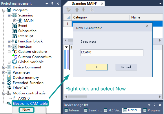
(1) In the project management window, right-click [Electronic Cam Table], click [New], enter the table name, and click [OK] to create an electronic cam table.
(2) Open the newly created electronic cam table and enter the relevant configuration interface.
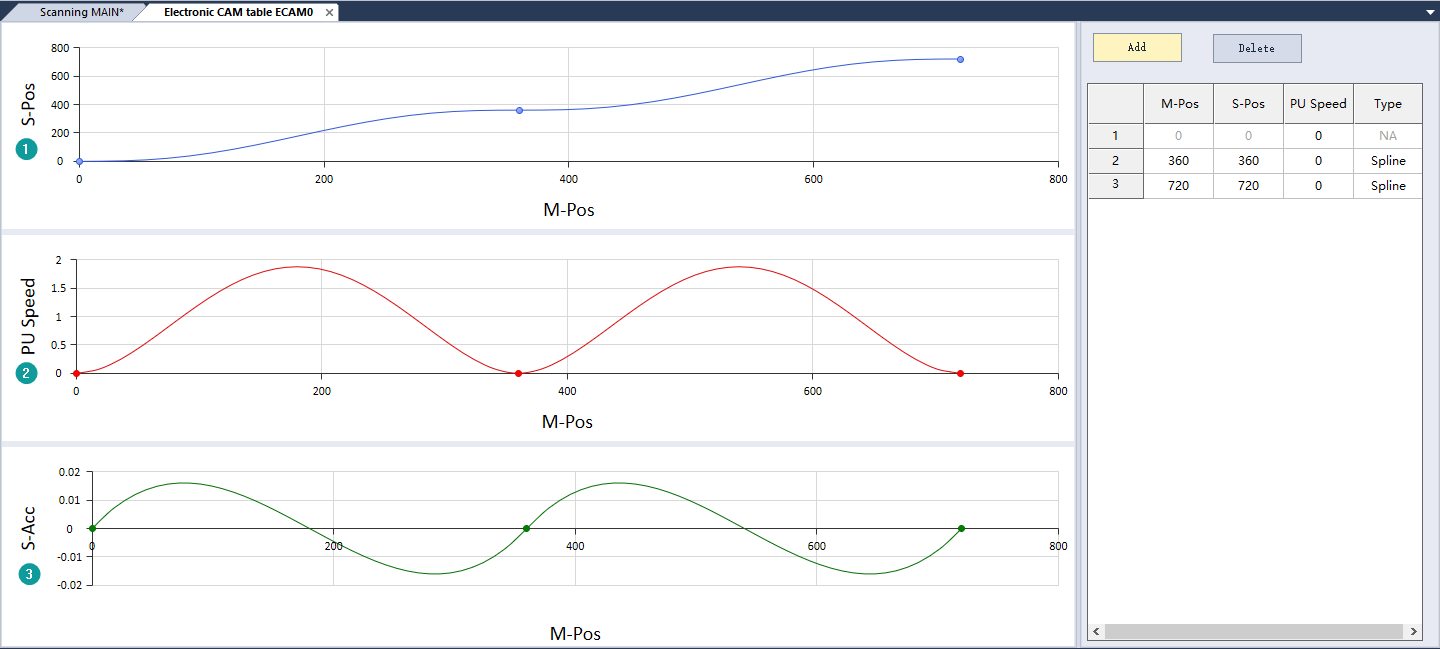
(3) Curve description: ①SPos: displacement curve; ②PU Speed: Speed curve; ③S-Acc: Acceleration curve.
(4) The middle key point of the displacement curve allows dragging up, down, left, and right, and the rightmost key point allows dragging up and down; the speed curve only allows the middle key point to be dragged up and down; the acceleration curve does not allow dragging.
Data Configuration
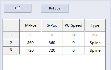
① MPos: master axis phase, set the phase of the master axis, the data range is 0 to 9999999;
② SPos: slave axis displacement, set the offset position of the slave axis, data range: -9999999 to 9999999;
③ PU Speed: connection speed, data range: -9999999 to 9999999;
④ Type: curve type; Line: straight line; Spline: 5th degree curve;
⑤ Table data configuration description: the master axis phase and slave axis offset of the first point are 0 by default and cannot be changed; the value of the next point of the master axis phase must be greater than the value of the previous point; the last point of the master axis determines the period of the master axis, so there is no need to set the cycle separately.
E-CAM Table Download
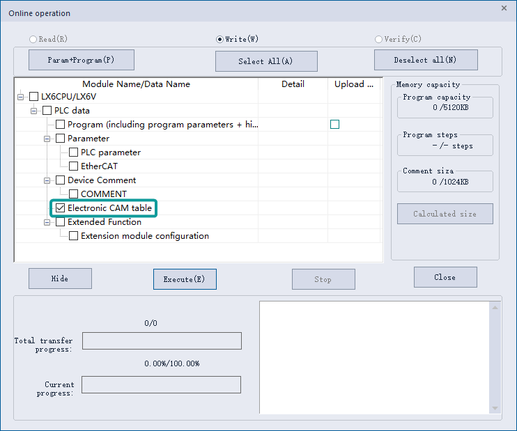
On the PLC download page, check the name of the electronic cam table to be downloaded, click "Execute", and wait for the PLC to be written; when there is an electronic cam table, the download page will display the electronic cam table checkbox, otherwise it will not be displayed; after checking, all electronic cam tables are downloaded.
Caution
Description of the function disable instructions
| Project management | Extended function | Electronic CAM table | No |
|---|---|---|---|
| Edit Function | Comment edit | No | |
| Statement editor | No | ||
| Switch | No | ||
| Communication related | PLC checksum | Detail check | No |
| U disk download | No | ||
| Generate download file | No | ||
| Calculation of total program steps | No | ||
| Monitor edit (W) | No | ||
| Module monitoring | No |
Shortcut Keys
For general shortcut keys, refer to the “Software Help” in PLC Editor2 software. The following table shows the shortcut keys available in the Ladder Diagram Editor.
| Shortcut key | Summary |
|---|---|
| F5 | Normally open contact |
| Shift+F5 | Normally open contact OR |
| F6 | Normally closed contact |
| Shift+F6 | Normally closed contact OR |
| F7 | Coil |
| F8 | Application instruction |
| F9 | Horizontal line input |
| F11 | Vertical line input |
| Ctrl+F9 | Delete horizontal line |
| Ctrl+F11 | Delete vertical line |
| Shift+F7 | Rising edge pulse |
| Shift+F8 | Falling edge pulse |
| Ctrl+Alt+F7 | Parallel rising edge pulse |
| Ctrl+Alt+F8 | Parallel falling edge pulse |
| Ctrl+Alt+F11 | Invert the result of the operation |
| Shift+F9 | Continuous underline |
| Shift+F11 | Continuous strikethrough |
| Alt+F5 | MEP |
| Ctrl+Alt+F5 | MEF |
| Shift+Insert | Insert program line |
| Shift+Delete | Delete row |
| Ctrl+Insert | Insert column |
| Ctrl+Delete | Delete column |
| Ctrl + → | Underline |
| Ctrl + ← | Underline |
| Ctrl + ↓ | Underline |
| Ctrl + ↑ | Underline |
| Ctrl+/ | Normally open/normally closed/rising edge/falling edge contact switching |
| Ctrl+F5 | Comment display |
| F1 | Open instruction help |
| HOME | Beginning of line |
| Ctrl+HOME | First line |
| END | End of line |
| Ctrl+END | End of program |
| PAGE UP | Previous page |
| PAGE DOWN | Next page |
| Backspace | Delete |
| Delete | Delete |
| Shift+N | Insert network |
| Shift+Ctrl+N | Insert network below |
| Shift+D | Delete network |
| F2 | Insert a concatenation operation block |
| Shift+F2 | Insert a parallel operation block |