Rockwell
DF1
MicroLogix 1000/1100/1200/1400/1500; SLC 5/03 5/04 5/05; PLC-5
HMI Settings
| Item | Recommended | Note |
|---|---|---|
| Protocol | Rockwell DF1 | |
| Connection | RS232 | |
| Baud rate | 19200 | |
| Stop bits | 1 | |
| Data bits | 8 | |
| Parity | None | |
| PLC Station No. | 1 | |
| HMI Station No. | 0 |
PLC Settings
DF1 Full Duplex protocol and CRC error check
Address List
| Type | Device registers | Format | Range | Note |
|---|---|---|---|---|
| Bit | I | I ddd.dd | 0.0~255.15 | Only able to communicate with file number I1 |
| O | O ddd.dd | 0.0~255.15 | Only able to communicate with file number O0 | |
| B | B nnhh.dd | 0.0~ffff.15 | Only able to communicate with file number B3 | |
| S | S ddd.dd | 0.0~255.15 | Only able to communicate with file number S2 | |
| N | N nnhh.dd | 0.0~ffff.15 | Only able to communicate with file number N7 | |
| Word | S | S ddd | 0~255 | Only able to communicate with file number S2 |
| TS | TS nnhh | 0~ffff | Only able to communicate with file number T4 (Timer Preset Value) | |
| TP | TP nnhh | 0~ffff | Only able to communicate with file number T4 (Timer Accumulator Value) | |
| CS | CS nnhh | 0~ffff | Only able to communicate with file number C5 (Counter Preset Value) | |
| CP | CP nnhh | 0~ffff | Only able to communicate with file number C5 (Counter Accumulator Value) | |
| N | N nnhh | 0~ffff | Only able to communicate with file number N7 |
Cable Wiring

DF1 Advanced
MicroLogix 1000/1100/1200/1400/1500; SLC 5/03 5/04 5/05; PLC-5
HMI Settings
| Item | Recommended | Note |
|---|---|---|
| Protocol | Rockwell DF1 Advanced | |
| Connection | RS232 | |
| Baud rate | 19200 | |
| Stop bits | 1 | |
| Data bits | 8 | |
| Parity | None | |
| PLC Station No. | 1 | |
| HMI Station No. | 0 |
PLC Settings
DF1 Full Duplex protocol and CRC error check
Address List
| Type | Device registers | Format | Range | Note |
|---|---|---|---|---|
| Bit | I1 | I1ddd.dd | 0.0~255.15 | Only able to communicate with file number I1 |
| O0 | O0ddd.dd | 0.0~255.15 | Only able to communicate with file number O0 | |
| S2 | S2ddd.dd | 0.0~255.15 | Only able to communicate with file number S2 | |
| B3 | B3ddd.dd | 0.0~255.15 | Only able to communicate with file number B3 | |
| BN | BNddddd.dd | 0.0~99255.15 | Bit data file B0~B99 First two digits is for file number For example, BN13001.00 represents file number B13, address 001, the 0th bit. | |
| N7 | N7ddd.dd | 0.0~255.15 | Only able to communicate with file number N7 | |
| NN | NNddddd.dd | 0.0~99255.15 | Integer data file bit format N0~N99 First two digits is for file number For example, NN13001.00 represents file number N13, address 001, the 0th bit. | |
| Word | S2 | S2ddd | 0~255 | Only able to communicate with file number S2 |
| T4S | T4Sddd | 0~255 | Only able to communicate with file number T4 (Timer Preset Value) | |
| T4P | T4Pddd | 0~255 | Only able to communicate with file number T4 (Timer Accumulator Value) | |
| TNS | TNSddddd | 0~99255 | Timer Preset Value First two digits is for file number For example, TNS99255 represents file number T99, address 255. | |
| TNP | TNPddddd | 0~99255 | Timer Accumulator Value First two digits is for file number For example, TNP99255 represents file number T99, address 255. | |
| C5S | C5Sddd | 0~255 | Only able to communicate with file number C5 (Counter Preset Value) | |
| C5P | C5Pddd | 0~255 | Only able to communicate with file number C5 (Counter Accumulator Value) | |
| CNS | CNSddddd | 0~99255 | Counter Preset Value First two digits is for file number For example, CNS99255 represents file number C99, address 255. | |
| CNP | CNPddddd | 0~99255 | Counter Accumulator Value First two digits is for file number For example, CNP99255 represents file number C99, address 255. | |
| N7 | N7ddd | 0~255 | Only able to communicate with file number N7 | |
| NN | NNddd | 0~99255 | Integer data file First two digits is for file number For example, NN99255 represents file number N99, address 255. | |
| Double Word | F8 | F8ddd | 0~255 | Only able to communicate with file number F8 |
| FN | FNddddd | 0~99255 | Floating point data file First two digits is for file number For example, FN99255 represents file number F99, address 255. | |
| LN | LNddddd | 0~99255 | Long |
Cable Wiring
MicroLogix
MicroLogix 1000/1100/1200/1400/1500; SLC 5/03 5/04 5/05 PLC-5
HMI Settings
| Item | Settings | Note |
| Protocol | Allen-Bradlley MicroLogix | |
| Connection | RS232 | |
| Baud rate | 19200 | |
| Data bit | 8 | |
| Parity | None | |
| Stop bit | 1 | |
| PLC station No. | 1 |
Address List
| Type | Device registers | Format | Range | Note |
| Bit | I | I d.d | 0.0~255.15 | |
| O | O d.d | 0.0~255.15 | ||
| B | B nnhh.dd | 0.0~ffff.15 | nn: block number (hex) | |
| S | S d.d | 0.0~255.15 | ||
| N | N nnhh.dd | 0.0~ffff.15 | nn: block number (hex) | |
| Word | S | S d | 0~255 | |
| TS | TS nnhh | 0~ffff | nn: block number (hex) | |
| TP | TP nnhh | 0~ffff | ||
| CS | CS nnhh | 0~ffff | ||
| CP | CP nnhh | 0~ffff | ||
| N | N nnhh | 0~ffff | ||
| C | C nnhh | 0~ffff | ||
| T | T nnhh | 0~ffff | ||
| R | R nnhh | 0~ffff |
Cable Wiring

EtherNet/IP(CompactLogix Series)
Allen-Brandly Compact Logix Free Tag
HMI Settings
| Items | Settings | Note |
| Protocol | EtherNet/IP(CompactLogix Series) | |
| Connection | Ethernet | |
| Port No. | 44818 |
PLC Setting
Create new tags

Export tags to CSV file. ([Tools] » [Export] » [Tags and Logic Comments])

Import labels, please open [Communication] window and click [Import label];
Select csv file, all tags will be displayed as belows;

✎Note:
Because in different region, the separation symbol is different, we suggest you check this before you want to import your tags. To open csv file as text format.

The directory of changing system settings: [Control Panel] -> [Date, Time, Language,and Regional Options] -> [Change the format of numbers, dates, and times]->[Customize]-> [List separator]. Please select [,] and export CSV file after setting.
Communication settings in HMI
Enable HMI Ethernet in [Project Settings];

Set PLC IP in [Device IP] settings;

Cable Wiring

MicroLogix 1200
The operational address is determined by the connection of Allen-Bradley PLC to HMI. For extension modules or other special conditions, refer to allen-Bradley PLC instruction manual. The following is an example of allen-bradley MicroLogix1200.
- Bit address I: The address ranges from 0.0 to 255.15. The value of the data before the decimal point ranges from 0 to 255 (decimal). The value from 0 to 15 after the decimal point is the sub address (decimal).
- Bit address B: The address ranges from 000.0 to fff.15. The first f from left to right represents the block number (hexadecimal); The second and third f from left to right represent the word address (hexadecimal). The value 0 to 15 after the decimal point reprensents the sub address (decimal).
- Word address S: The word address ranges from 0 to 255 (decimal).
- Word address TS: The address ranges from 000.0 to ffff. The first and second f from left to right represents the block number (hexadecimal); The third and fourth f from left to right represent the word address (hexadecimal).
✎Note: Register address TP, CS, CP, N, F and TS address edit are same. D indicates decimal, and F indicates hexadecimal. Different PLC models may support different registers. See the following table.
| PLC bit address type | Address format | Address range |
| I | dd.dd | I 0.0 ~ 255.15 |
| O | dd.dd | O 0.0 ~ 255.15 |
| B | fff.dd | B 000.0 ~ fff.15 |
| S | dd.dd | S 0.0 ~ 255.15 |
| N | ffff.dd | N 000.0 ~ fff.15 |
| PLC word address type | Address format | Address range |
| S | ddd | S0 ~ 255 |
| TS | ffff | TS0 ~ FFFF |
| TP | ffff | TP0 ~ FFFF |
| CS | ffff | CS0 ~ FFFF |
| CP | ffff | CP0 ~ FFFF |
| N | ffff | N0 ~ FFFF |
| F | ffff | F0 ~ FFFF |
Ethernet/IP DF1
Supported Series: Rockwell MicroLogix 1100, 1400, SLC5/05 Ethernet port. MicroLogix1000,1200,1500,SLC 5/03, 5/04 with 1761-NET-ENI
| Items | Settings | Note |
| Protocol | Rockwell Ethernet/IP DF1 | |
| Connection | Ethernet | |
| Port No. | 44818 | |
| PLC station No. | 1 |
Address List
| Type | Device registers | Format | Range | Note |
|---|---|---|---|---|
| Bit | I1 | I1ddd.dd | 0.0~255.15 | Only able to communicate with file number I1 |
| O0 | O0ddd.dd | 0.0~255.15 | Only able to communicate with file number O0 | |
| S2 | S2ddd.dd | 0.0~255.15 | Only able to communicate with file number S2 | |
| B3 | B3ddd.dd | 0.0~255.15 | Only able to communicate with file number B3 | |
| BN | BNddddd.dd | 0.0~99255.15 | Bit data file B0~B99 First two digits is for file number For example, BN13001.00 represents file number B13, address 001, the 0th bit. | |
| N7 | N7ddd.dd | 0.0~255.15 | Only able to communicate with file number N7 | |
| NN | NNddddd.dd | 0.0~99255.15 | Integer data file bit format N0~N99 First two digits is for file number For example, NN13001.00 represents file number N13, address 001, the 0th bit. | |
| Word | S2 | S2ddd | 0~255 | Only able to communicate with file number S2 |
| T4S | T4Sddd | 0~255 | Only able to communicate with file number T4 (Timer Preset Value) | |
| T4P | T4Pddd | 0~255 | Only able to communicate with file number T4 (Timer Accumulator Value) | |
| TNS | TNSddddd | 0~99255 | Timer Preset Value First two digits is for file number For example, TNS99255 represents file number T99, address 255. | |
| TNP | TNPddddd | 0~99255 | Timer Accumulator Value First two digits is for file number For example, TNP99255 represents file number T99, address 255. | |
| C5S | C5Sddd | 0~255 | Only able to communicate with file number C5 (Counter Preset Value) | |
| C5P | C5Pddd | 0~255 | Only able to communicate with file number C5 (Counter Accumulator Value) | |
| CNS | CNSddddd | 0~99255 | Counter Preset Value First two digits is for file number For example, CNS99255 represents file number C99, address 255. | |
| CNP | CNPddddd | 0~99255 | Counter Accumulator Value First two digits is for file number For example, CNP99255 represents file number C99, address 255. | |
| N7 | N7ddd | 0~255 | Only able to communicate with file number N7 | |
| NN | NNddd | 0~99255 | Integer data file First two digits is for file number For example, NN99255 represents file number N99, address 255. | |
| Double Word | F8 | F8ddd | 0~255 | Only able to communicate with file number F8 |
| FN | FNddddd | 0~99255 | Floating point data file First two digits is for file number For example, FN99255 represents file number F99, address 255. | |
| LN | LNddddd | 0~99255 | Long |
PLC Setting:
1.Open the RSLinx Classic Lite software and click [Configure Drivers...] in [Communications].
2.Click the drop-down menu and select EtherNet/IP driver
3.Click Add New and a pop-up window will pop up. Name the driver and click [OK] in the pop-up window.
4.The configuration driver window pops up., click on the correct network adapter option (such as the ASIX USB to Fast Ethernet Family Adapter option in this picture), and click OK

5.Click the [Close] button.
6.Click the [RSWho] button.
7.Pop up the RS Who window, indicating that the driver has been added successfully.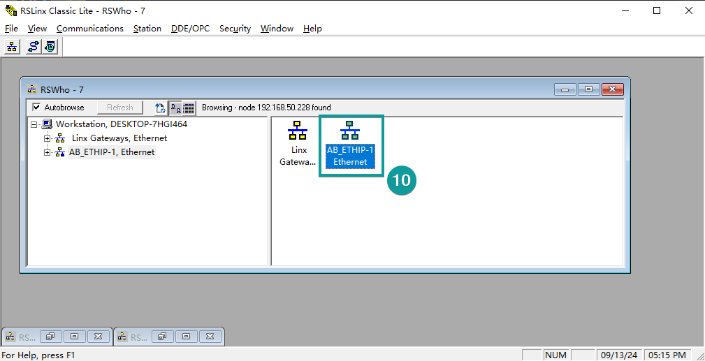
8.Open the RSLogix 500Pro software and select [System Comms...] in the [Comms] option.
9.Select the driver you have created. All device nodes in the same LAN as the computer will be scanned. Select the PLC to be connected and click [OK].

10.Click Comms [Go Online].
11.Click [YES] in the pop-up window.
12.Enter online mode.
Cable Wiring

Rockwell EtherNet/IP(CompactLogix Series)
Supported Series: Rockwell CompactLogix Series Ethernet
| Items | Settings | Note |
| Protocol | Rockwell EtherNet/IP (CompactLogix Series) | |
| Connection | Ethernet | |
| Port No. | 44818 | |
| PLC station No. | 1 |
Support Variable Type
| PLC data type | Bit/Word | PIStudio data format | Memo |
| BOOL | Boolean | Bit object | |
| BitArray | |||
| SINT | -128-127 | ||
| USINT | 0~255 | ||
| INT | Integer | 16-bit signed, ASCll | -32768~32767 |
| UINT | 0~65535 | ||
| DINT | Double integer | 32-bit signed | -2^31~(2^31-1) |
| UDINT | 0~4294967295 | ||
| REAL | Single Precision Float | 32-bit floating | |
| LINT | Long integer | 64-bit signed | |
| ULINT | Long integer | 64-bit unsigned | |
| LREAL | Double Precision Float | 64-bit double | |
| STRING | Enable Read DWord |
PLC Setting:
1.Open the RSLinx Classic Lite software and click [Configure Drivers...] in [Communications].

2.Click the drop-down menu and select EtherNet/IP driver

3.Click Add New and a pop-up window will pop up. Name the driver and click [OK] in the pop-up window.

4.The configuration driver window pops up., click on the correct network adapter option (such as the ASIX USB to Fast Ethernet Family Adapter option in this picture), and click [OK].

5.Click the [Close] button

6.Open Stuido5000 and create a new project or open an existing project.
To create a new project: click [New Project].

7.Click the [1769-L16ER-BB1B]→ Edit Project Name → Select the file storage location → [Next]

8. Select the software version →Select [Expansion I/O] number→ Security Authority → Click [Finish].
The software version must be the same as the PLC firmware version, and the Security Authority protection should be selected according to personal needs.

Create a new tag
1.Click the drop-down menu on the left of [Controller ABcs]→ Right-click [Controller Tags] → Click [New tag].

2.Input tag name → Select tag type → Create

Establishing communication
1.Click [Communications]→Click[Who Active].

2.Select the drive → Select the corresponding PLC →Click [Go Online].
The driver is a new created driver from step 1.2

3.Click [Download]

4.Click [Download]→ [YES].


Export Tags
1.Click the drop-down menu on the left of [Controller ABcs]→Right-click [Controller Tags]→ Click [Export Tags].

2.Edit the tag file name → Select the file storage location → [Export].

HMI Setting:
① [Project]→[Communication]→[Setting]

② Choose protocol:
Device type [Rockwell]→[Rockwell EtherNet/IP(CompactLogix Series)]→[OK]

③[Setting]→[PLC IP Address]→[OK]→[Labels manage].

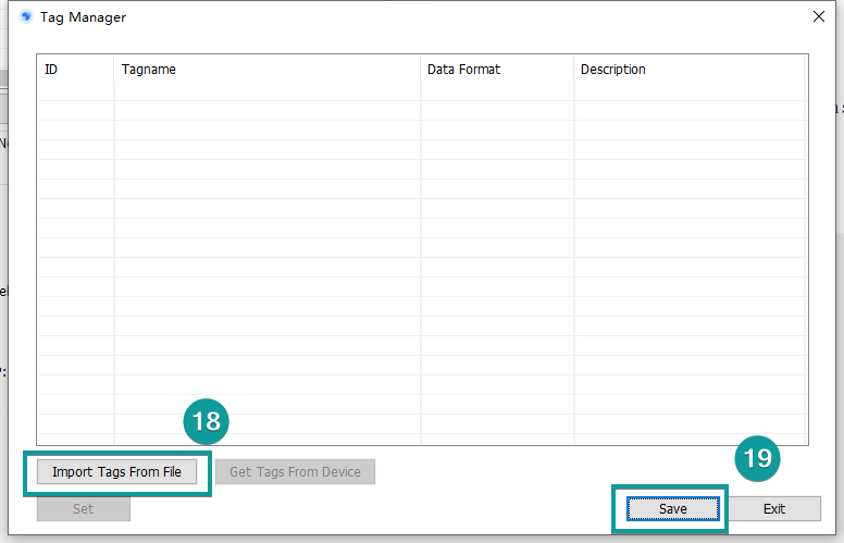
④Tags import:
[Import Tags From File]→Choose the .CSV file→[Open]→[Save]→[OK]
Project making
①Using PIStudio to program a HMI project depending on the requirements.

②After programming[Compile], you can download the project into HMI when compilation complete.
