Schneider
Schneider Modicon MODBUS RTU
HMI Setting
| Parameters | Recommended | Notes |
|---|---|---|
| Protocol | Schneider Modicon MODBUS RTU | |
| Connection | RS485 | |
| Baud rate | 19200 | |
| Data bit | 8 | |
| Parity | Even | |
| Stop bit | 1 | |
| PLC station No. | 1 |
PLC Setting
| Communication mode | Modbus RTU protocol |
|---|
Device Address
| Bit/Word | Device type | Format | Range | Memo |
|---|---|---|---|---|
| B | IX | DDDDDo | 0 ~ 655357 | Input bit (read only) |
| B | QX | DDDDDo | 0 ~ 655357 | Write multiple coils |
| B | MX | DDDDDDo | 0 ~ 9999997 | Output register bit (octal) |
| W | MW | DDDDDD | 0 ~ 999999 | Output register |
| DW | MD | DDDDDD | 0 ~ 999999 | Output register |
Wiring Diagram
RS-485 2W (RJ45 Connector): The following is the view from the soldering point of a connector.

TM218 Series
HMI Setting
| Parameters | Recommended | Notes |
|---|---|---|
| Protocol | TM218 Series | |
| Connection | RS485 | |
| Baud rate | 19200 | |
| Data bit | 8 | |
| Parity | Even | |
| Stop bit | 1 | |
| PLC station No. | 1 |
Device Address
| Bit/Word | Device type | Format | Range |
|---|---|---|---|
| B | IX | IX dddd.d | 0 to 65535 |
| B | QX | QX dddd.d | 0 to 65535 |
| B | MX | MX dddd.dd | 0 to 999999 |
| W | MW | MW dddd | 0 to 999999 |
Configure the communication protocol


PLC Setting:
Open SoMachine Central, create a new project or open the project that has been created.
Create new project: [Create a new project]→[Empty Project]→[OK]→[Open Configuration]


Into the [Open Configuration].
[Untitled]→[Add Device]→[Logic Controller]→[M218]→[TM218LDA16DRN]

PLC Default Parameters:
In the Devices tree [MyController]→[Serial Line 2]→[Modbus_Manager]
Modbus:
[Transmission Mode] RTU→[Addressing] Slave
Serial Line Settings:
[Baud rate] 19200, [Data bits] 8, [Stop bits] 1, [Parity] EVEN, [Physical Medium] RS485

Cable Wiring

Schneider TM221 Ethernet
Supported Series: Modicon M221 Series
HMI Setting
| Items | Settings | Note |
| Protocol | Schneider TM221 | |
| Connection | Ethernet | |
| Port No. | 502 | |
| Device No. | 1 | |
| HMI No. | 0 |
Address List
| Type | Address Type | Format | Range | Note |
|---|---|---|---|---|
| Bit | IWMB | IWMB DD.dd | 0~20.15 | Output Register(Bit type) |
| QWMB | QWMB DD.dd | 0~20.15 | Input Register(Bit type) | |
| MWB | MWB DDDD.dd | 0~8000.15 | Internal memory word(Bit type) | |
| M | M DDDD | 0~1024 | Internal memory bit | |
| IWB | IWB DDDDDD.dd | 0~255255.15 | Analog Input(Bit type) | |
| I | I DDD.dd | 0~255.13 | Digital Input | |
| Q | Q DDD.d | 0~255.9 | Digital Output | |
| S | S DDD | 0~159 | System Bit | |
| Word | IWM | IWM DD | 0~20 | Output Register |
| QWM | QWM DD | 0~20 | Input Register | |
| MW | MW DDDD | 0~7999 | Internal memory word | |
| MD | MD DDDD | 0~7998 | Internal memory double word | |
| MF | MF DDDD | 0~7998 | Internal memory floating point | |
| IW | IW DDDDDD | 0~255255 | Analog Input | |
| SW | SW DDD | 0~233 | System word | |
| KW | KW DDD | 0~511 | Constant word | |
| KD | KD DDD | 0~510 | Internal constant double word | |
| KF | KF DDD | 0~510 | Internal constant floating point | |
| TM_V | TM_V DDD | 0~254 | Timer | |
| TM_P | TM_P DDD | 0~254 | Timer |
PLC Settings
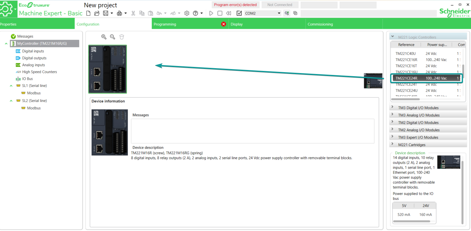
1.Open the software EcoStruxure Machine Expert - Basic, drag the corresponding model from M221 Logic Controller list into the [Configuration] tab.
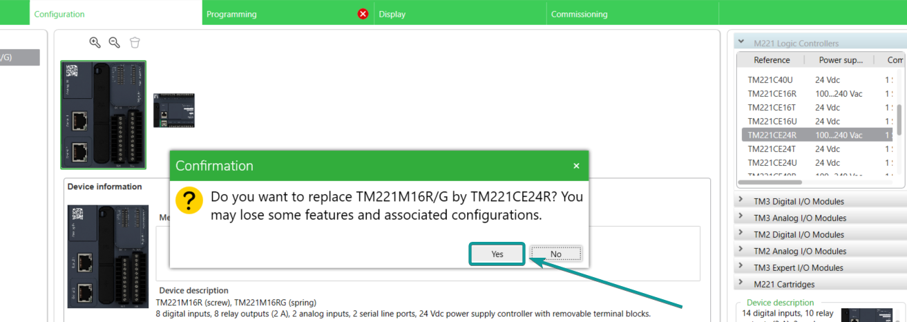
2.Click [Yes] to replace the model in current project.
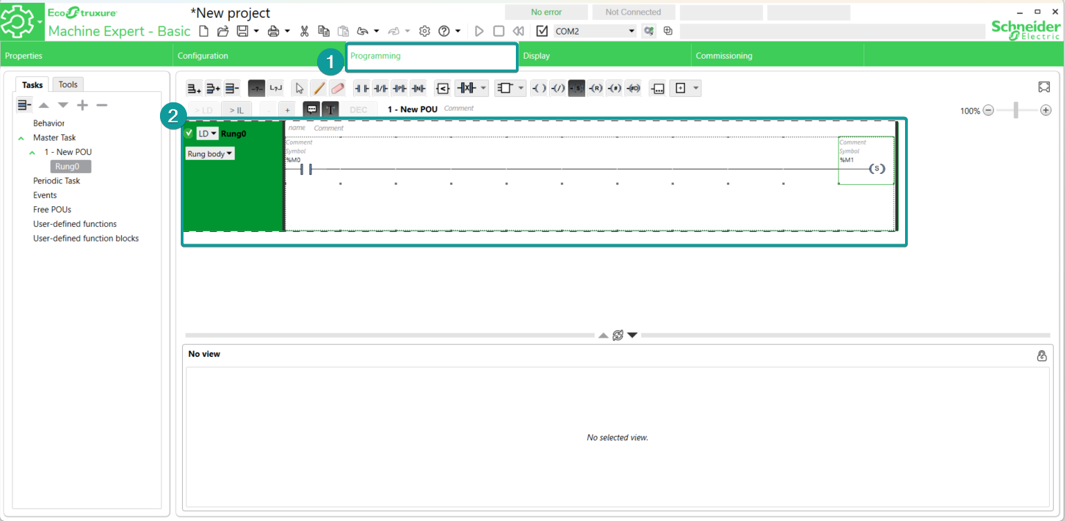
3.Program the PLC project in [Programming] tab.
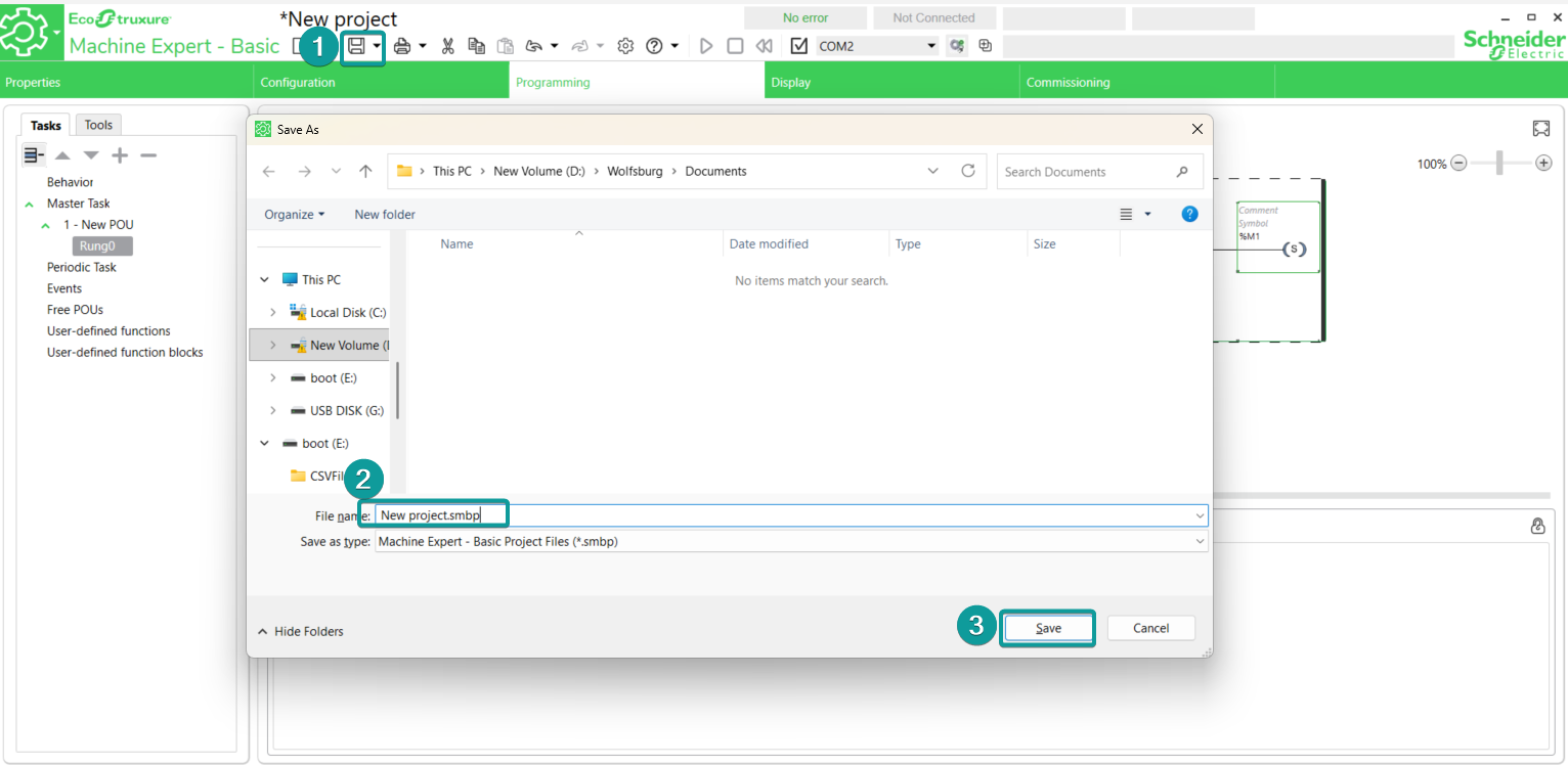
4. Click [Save] to save the project file.
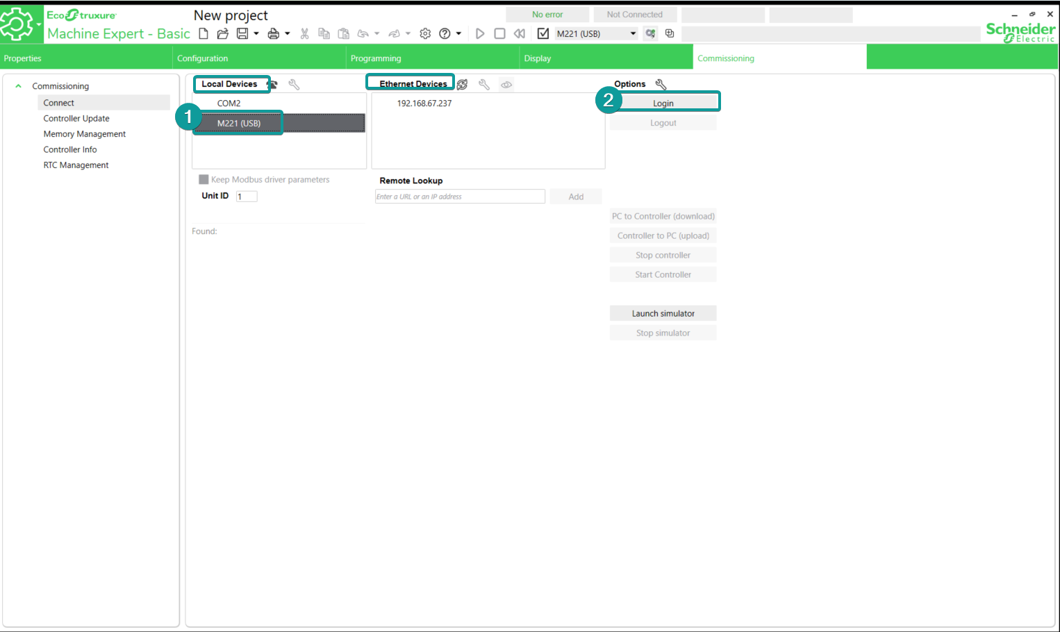
5. Go to the Commissioning tab to log in the PLC. Choose either Local Devices(USB or COM) or Ethernet Devices. Example here uses USB(mini USB port) to log in the PLC.
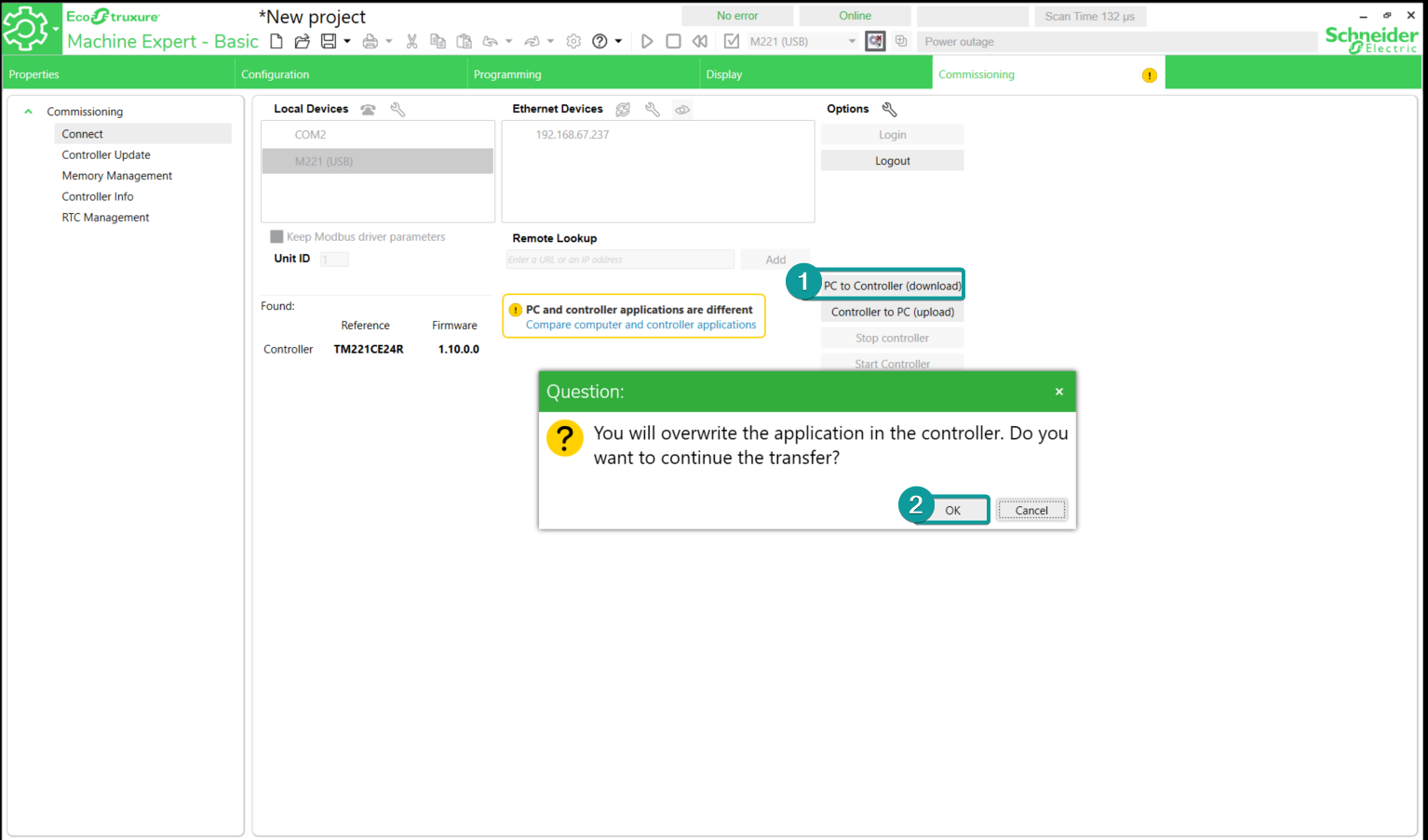
6. Click [PC to Controller (download)], then click OK.
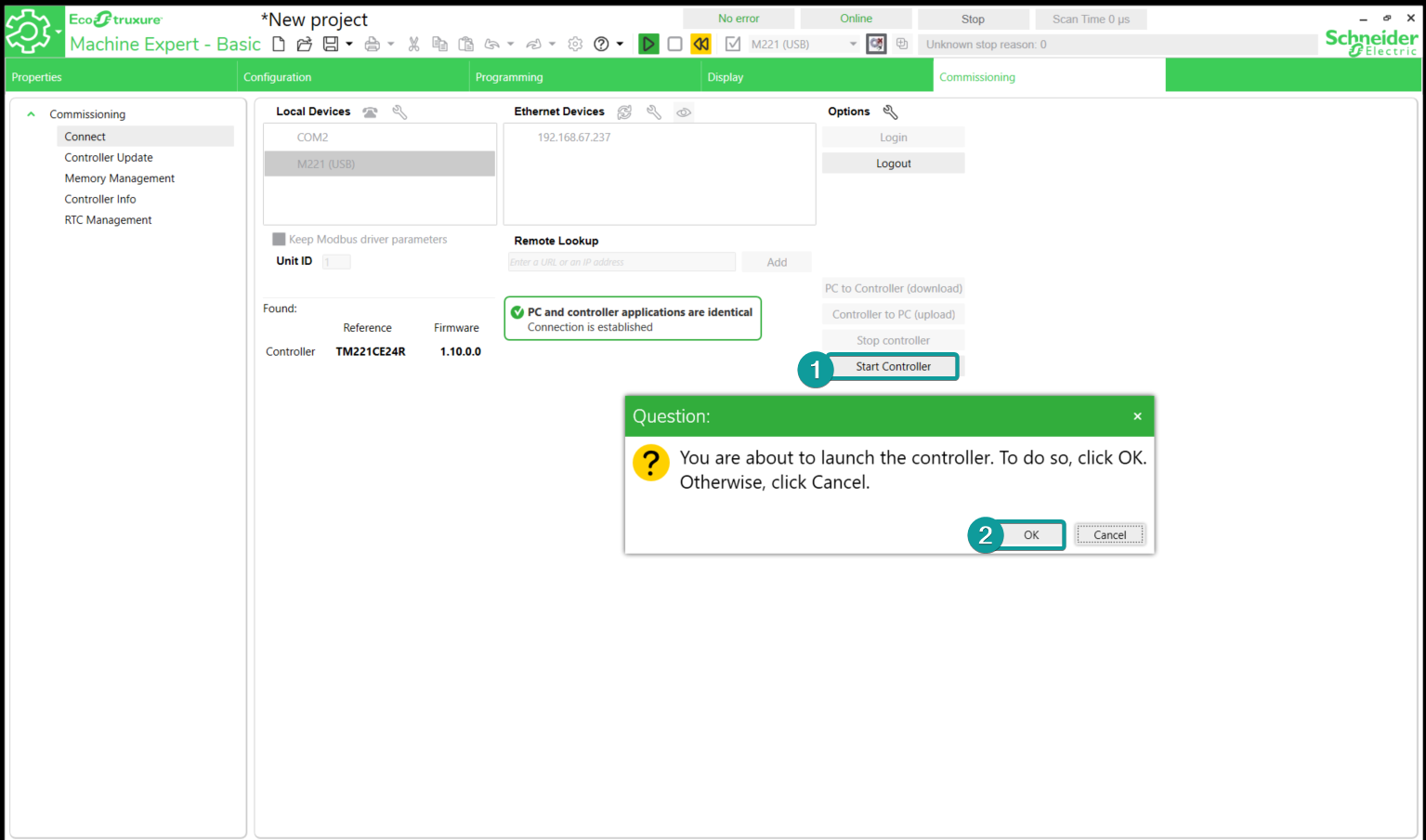
7. Click [Start controller] to run the program.
PIStudio Setting
1. Create new project

2. Select the protocol as Schneider TM221 Ethernet

3. Change the Device IP according to the PLC actual IP settings.
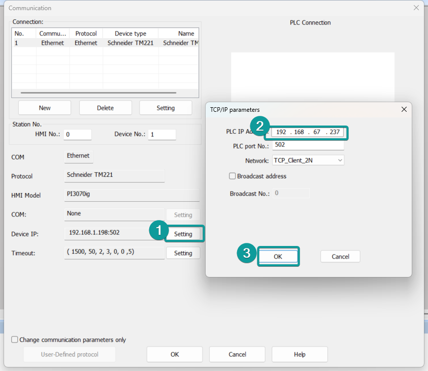
4. Click OK to save the communication settings.
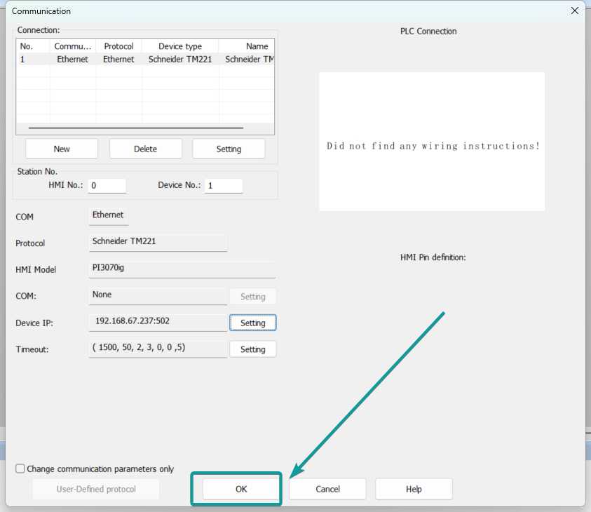
5. Add the communication address according to the PLC program, then download into the HMI.