5-5 Counter
Counter
Counter performs counting function, it contains coil, contact and count value register. The current value of the counter increases each time coil C0 is turned ON. The output contact is activated when count value reach to preset value.
Counters which are latched are able to retain their status information, even after the PLC has been powered down. This means on re-powering up, the latched counters could immediately resume from where they were at the time of the original PLC power down.
Devices numbered in: Decimal, i.e. C0 to C9, C10 to C19
Table 1
| PLC | 16bit UP Counters 0 – 32,767 | 32bit Bi-directional Counters -2,147,483,648 - +2,147483647 | ||
| General | Latched | General | Latched | |
| LX1S | 16 (C0 – C15) ※3 | 16 (C16 – C31) ※3 | - | - |
| LX2N | 100 (C0-C99) ※1 | 100(C100 – C199) ※2 | 20 (C200 – C219) ※1 | 15 (C220 – C234) ※2 |
| LX3V | 100 (C0-C99) ※1 | 100(C100 – C199) ※2 | 20 (C200 – C219) ※1 | 15 (C220 – C234) ※2 |
※1, Non-latched area, it could be changed to latched area by parameter setting.
※2, Latched area, it could be changed to non-latched area by parameter setting.
※3, The non-latched or latched feature couldn’t be changed.
16bit up counter
16bit counters: 1 to +32,767, as below picture shows, the current value of the counter increases each time coil C0 is turned ON by X2. The output contact is activated when the coil is turned ON for the tenth time.
After this, the counter data remains unchanged when X2 is turned ON. The counter current value is reset to ‘0’ (zero) when the RST instruction is executed by turning ON X1 in the example. The output contact Y0 is also reset at the same time.
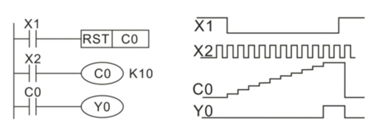
Figure 2
32bit bi-directional counter
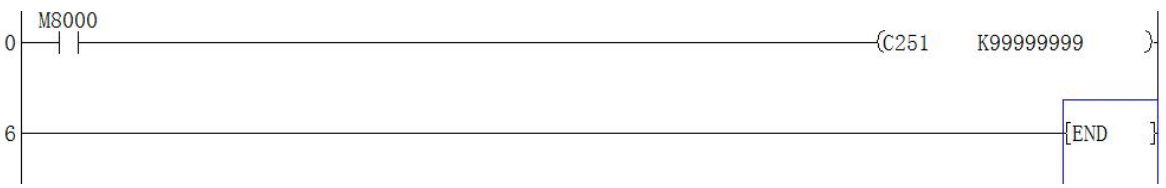
32bit bi-directional counters: -2,147,483,648 to +2,147,483,647. C200- 219 are general, C220- 234 are latched.
The counting direction is designated with special auxiliary relays M8200 to M8234. When the special auxiliary relay is ON, it is decremented; otherwise, it is counting up.
High speed counter
Although counters C235 to C255 (21 points) are all high speed counters, they share the same range of high speed inputs. Therefore, if an input is already being used by a high speed counter, it couldnot be used for any other high speed counters or for any other purpose, i.e as an interrupt input.
The selection of high speed counters is not free, they are directly dependent on the type of counter required and which inputs are available.
- Available counter types
- 1 phase with user start/reset: C235 to C240
- 1 phase with assigned start/reset: C241 to C245
- 2 phase bi-directional: C246 to C250
- A/B phase type: C251 to C255
Different types of counters could be used at the same time but their inputs must not coin-cider. Inputs X0 to X7 couldnot be used for more than one counter.
Table 3
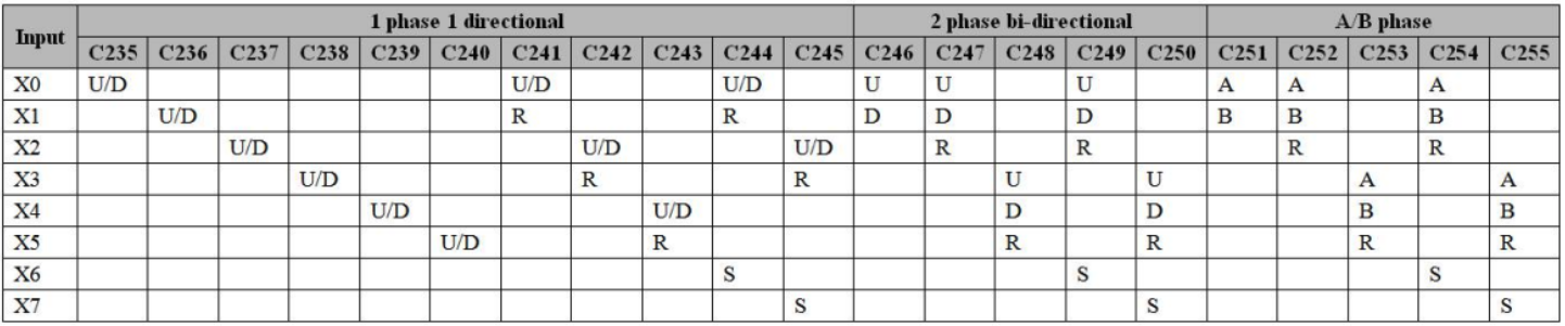
U: up counter input
D: down counter input
R: reset counter (input)
S: start counter (input)
A: A phase counter input
B: B phase counter input
1 phase
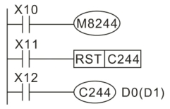
Figure 4
As above program shows, C244 is 1 phase high speed counter with start, stop and reset functions. From the table, X1~X6 are for start and reset. C244 start counting when X12 and X6 are turned ON, the counter input terminal is X0, set value for C244 is determined by D0 (D1), so C244 could be reset by X0 or X11.
2 phase
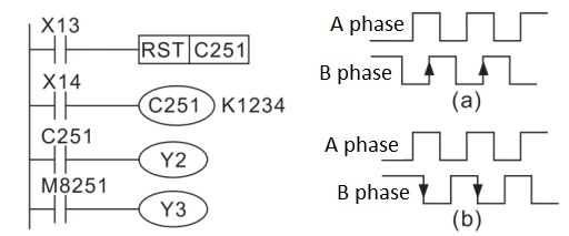
Figure 5
C251~C255 are 2 phase (AB phase) high speed counter. As above (b) picture shows, C251 counts according from X0 (A phase) and X1 (B phase), when X14 is turned ON. C251 is reset when X13 is turned ON.
While A phase is turned ON, if B changes state from OFF to ON, C251 executes up count operation. While A phase is turn ON, if B changes state from ON to OFF, C251 executes down count operation. According to this principle, C251 executes up count operation while machine forward, and C251 executes down count operation while machine reverse. The M8251 monitors the C251's up / down counting status, OFF is for up counting, ON is for down counting.
Output Y: high speed pulse output transistor
- It supports up to 4 channels, and each channel maximum output frequency is 200K;
- The output frequency could be used for controlling inverter, stepper and servo motors and so on;
Input X: one phase
- X0, X1 hardware counters (C235, C236, C246), could support 200K pulse input at the same time;
- X0, X1 software counters (C241, C244, C247, C249), could support the input of 100K pulses at the same time;
- The hardware counter could be switched to software counting using HSCS, HSCR, HSZ instructions;
- The last four X points are software counting, which could support the input of 10K pulses at the same time.
Input X: A/B phase
- X0, X1 hardware counter (C251), can support 100K pulse input;
- X0, X1 software counters (C252, C254) support the simultaneous input of 50K pulses at the same time;
- Hardware counter can be switched to software counter, using HSCS, HSCR, HSZ instructions;
- The remaining X points are counted by software, and each 5K pulse frequency can be input at the same time;
- There are two frequency modes for 2 phase 2 input, one is 2 times, and the other is 4 times, as following table shows, users select mode in D8200;
Table 6
| Value in D8200 | Count icon |
K2 (two times) | 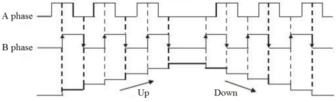 |
K4 or others (four times) (default) | 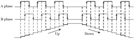 |
Note:
HSCS, HSCR and HSCZ couldn’t be used with Frequency multiplication
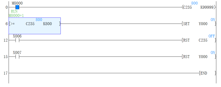
Program example1:
If X0 input pulse number >=800,The Y0 will set ON.
X6 means reset C235.
X7 means reset Y0.
You also could use M register instead of X registers.(M is a auxiliary register
Program example2: AB encoder