07 Convenient instructions
ABSD/BIN 16-bit data absolute method
ABSD
Create multiple output modes corresponding to the current counter (BIN 16-bit value).
-[ABSD (S1) (S2) (D) (N)]
Content, range and data type
| Parameter | Range | Data type | Data type (label) | |
| (S1) | The start device number storing the data tableContent (rising edge point and falling edge point) | - | Signed BIN 16 bit | ANY16 |
| (S2) | The counter number used for monitoring of the current value compared to the data table | - | Signed BIN 16 bit | ANY16 |
| (D) | The number of points of the output start device | - | Bit | ANY16_BOOL |
| (N) | Number of table rows and output bit device points | 1 to 64 | Signed BIN 16 bit | ANY16 |
Device used
| Instruction | Parameter | Devices | Offset modification | Pulse extension | |||||||||||||||
| Y | M | S | SM | D.b | KnX | KnY | KnM | KnS | T | C | D | R | SD | K | H | [D] | XXP | ||
| ABSD | Parameter 1 | ● | ● | ● | ● | ● | ● | ● | ● | ● | ● | ||||||||
| Parameter 2 | ● | ● | |||||||||||||||||
| Parameter 3 | ● | ● | ● | ● | ● | ● | |||||||||||||
| Parameter 4 | ● | ● | ● | ● | ● | ● | ● | ● | ● | ● | ● | ● | |||||||
Features
Take the turntable to rotate 1 revolution (0 to 360 degrees) to control the output ON/OFF as an example. (1 degree, 1 pulse angle signal)
Compare the data table of row (N) starting from (S1) (row (N) multiply by 2 points) with the current value of the counter (S2), from (D) to continuous (N) in the course of one revolution The output is ON/OFF control up to the point.
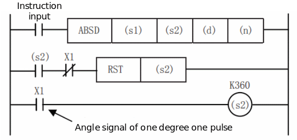
Use the transfer instruction to write the following data into (S1) to (S1)+2(N)-1 in advance. For example, the rising edge point data stores 16-bit data to even-numbered devices in advance, and the falling edge point data stores 16-bit data to odd-numbered devices in advance.
| Rising edge point | Falling edge point | Object output | ||
| - | Data value (example) | - | Data value (example) | |
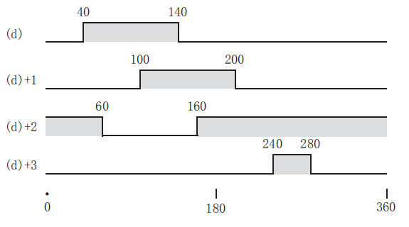
| (S1) | 40 | (S1)+1 | 140 | (D) |
| (S1)+2 | 100 | (S1) +3 | 200 | (D) +1 |
| (S1) +4 | 160 | (S1) +5 | 60 | (D) +2 |
| (S1) +6 | 240 | (S1) +7 | 280 | (D) +3 |
| ... | - | ... | - | ... |
| (S1)+2(N)-2 | (S1)+2(N)-1 | (D) +N-1 | ||
If the instruction input is set to ON, (D) is the start, (N) point is the output mode as shown below. Each rising edge point and falling edge point can be individually changed by rewriting the data from (S1) to (S1)+2(N)-1.
Error code
| Error code | Content |
| 4084H | When the value specified in (N) exceeds the range of 1 to 64 |
| 4085H | When the device specified in the read application instruction (S1), (S2 )and (N) exceeds the corresponding device range |
| 4086H | When the device specified in the write application instruction (D) exceeds the corresponding device range |
Example
Refer to the example in the function description.
DABSD/BIN 32-bit data absolute method
DABSD
Create multiple output modes corresponding to the current counter (BIN 32-bit value).
-[DABSD (S1) (S2) (D) (N)]
Content, range and data type
| Parameter | Content | Range | Data type | Data type (label) |
| (S1) | The start device number storing the data table (rising edge point and falling edge point) | - | Signed BIN 32 bit | ANY32 |
| (S2) | The counter number used for monitoring of the current value compared to the data table | - | Signed BIN 32 bit | ANY32 |
| (D) | The number of points of the output start device | - | Bit | ANY16_BOOL |
| (N) | Number of table rows and output bit device points | 1 to 64 | Signed BIN 32 bit | ANY32 |
Device used
| Instruction | Parameter | Devices | Offset modification | Pulse extension | |||||||||||||||||
| Y | M | S | SM | D.b | KnX | KnY | KnM | KnS | T | C | D | R | SD | LC | HSC | K | H | [D] | XXP | ||
| DABSD | Parameter 1 | ● | ● | ● | ● | ● | ● | ● | ● | ● | ● | ● | ● | ||||||||
| Parameter 2 | ● | ● | ● | ● | |||||||||||||||||
| Parameter 3 | ● | ● | ● | ● | ● | ● | |||||||||||||||
| Parameter 4 | ● | ● | ● | ● | ● | ● | ● | ● | ● | ● | ● | ● | ● | ● | |||||||
Features
Take the turntable to rotate 1 revolution (0 to 360 degrees) to control the output ON/OFF as an example. (1 degree, 1 pulse angle signal)
Compare the data table of row (N) starting from (S1) (row (N) × 4 points) with the current value of the counter (S2), from (D) to continuous (N) in the course of one revolution The output is ON/OFF control up to the point.
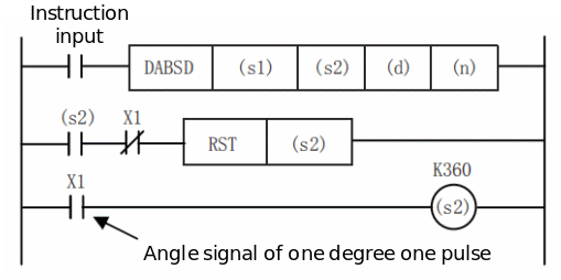
Use the transfer instruction to write the following data into (S1), (S1)+1 to (S1)+4(N)-2, (S1)+4(N)-1 in advance. For example, the rising edge point data stores 32-bit data to even-numbered devices in advance, and the falling edge point data stores 32-bit data to odd-numbered devices in advance.
| Rising edge point | Falling edge point | Object output | ||
| - | Data value (example) | - | Data value (example) | |
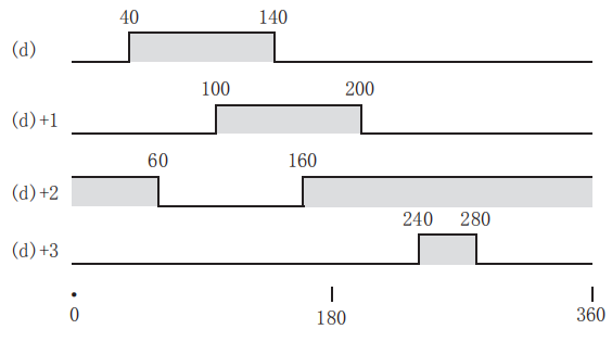
| (S1)+1, (S1) | 40 | (S1)+3, (S1)+2 | 140 | (D) |
| (S1)+5, (S1)+4 | 100 | (S1) +7, (S1) +6 | 200 | (D) +1 |
| (S1) +9, (S1) +8 | 160 | (S1)+11, (S1)+10 | 60 | (D) +2 |
| (S1) +13, (S1) +12 | 240 | (S1) +15, (S1) +14 | 280 | (D) +3 |
| ... | - | ... | - | ... |
(S1)+4(N)-3, (S1)+4(N)-4 | (S1)+4(N)-1, (S1)+4(N)-2 | (D) +N-1 | ||
If the instruction input is set to ON, (D) is the start, (NN) point is the output mode as shown below. Each rising edge point and falling edge point can be individually changed by rewriting the data from (S1) to (S1)+2(N)-1.
When specifying the number of bit devices in (S1), the device number should be a multiple of 16 (0, 16, 32, 64...), and only K8 should be specified for the number of bits.
The number of target output points is determined by the value of (N). (1≤(N)≤64)
Even if the instruction input is turned off, the output does not change.
Error code
| Error code | Content |
| 4084H | When the value specified in (N) exceeds the range of 1 to 64 |
| 4085H | When the device specified in the read application instruction (S1), (S2 )and (N) exceeds the corresponding device range |
| 4086H | When the device specified in the write application instruction (D) exceeds the corresponding device range |
Example
Refer to the example in the function description.
SER/16-bit data search
SER(P)
Search the same data and the maximum and minimum values from the data table.
-[SER (S1) (S2) (D) (N)]
Content, range and data type
| Parameter | Content | Range | Data type | Data type (label) |
| (S1) | Search for the start device number of the same data, maximum value, and minimum value | - | Signed BIN 16 bit | ANY16 |
| (S2) | Search for the value of the same data or its storage destination device number | - | Signed BIN 16 bit | ANY16 |
| (D) | Search for the same data, maximum value, minimum value and store the start device number | - | Signed BIN 16 bit | ANY16 |
| (N) | Search the number of same data, maximum and minimum | 1 to 256 | Signed BIN 16 bit | ANY16 |
Device used
| Instruction | Parameter | Devices | Offset modification | Pulse extension | ||||||||||
| KnX | KnY | KnM | KnS | T | C | D | R | SD | K | H | [D] | XXP | ||
| SER | Parameter 1 | ● | ● | ● | ● | ● | ● | ● | ● | ● | ● | ● | ||
| Parameter 2 | ● | ● | ● | ● | ● | ● | ● | ● | ● | ● | ● | ● | ● | |
| Parameter 3 | ● | ● | ● | ● | ● | ● | ● | ● | ● | ● | ||||
| Parameter 4 | ● | ● | ● | ● | ● | ● | ● | ● | ● | ● | ● | ● | ● | |
Features
For (S1) as the first (N) data, search for the same data as the BIN 16-bit data of (S2), and store the result in (D) to (D)+4.
In the case of the same data, the number of the same data, the first/final position, and the maximum and minimum positions of the same data are stored in the device with the first 5 points (D).
If there is no identical data, the number of identical data, the first/final position, and the maximum and minimum positions of the same data are stored in the device with the first 5 points (D). However, in (D) is the first 3 points of the device (the number of the same data, the first \\ final position), 0 is stored.
• The structure and data examples of the search result table are as follows. (N=10)
| The searched device (s1) | The value of the searched data (s1) | Comparison data (S2) value | Data location | search results | ||
| Maximum value (d) +4 | Consistent (d) | Minimum value (d+3) | ||||
| (s1) | K100 | K100 | 0 | ○(First time) | ||
| (s1)+1 | K111 | 1 | ||||
| (s1)+2 | K100 | 2 | ○ | |||
| (s1) +3 | K98 | 3 | ||||
| (s1) +4 | K123 | 4 | ||||
| (s1) +5 | K66 | 5 | ○ | |||
| (s1) +6 | K100 | 6 | ○ (final) | |||
| (s1) +7 | K95 | 7 | ||||
| (s1) +8 | 210 | 8 | ○ | |||
| (s1) +9 | K88 | 9 | ||||
• The search result table based on the above example is shown below.
| Device number | Content | Search result items |
| (d) | 3 | Number of identical data |
| (d) +1 | 0 | The position of the same data (first time) |
| (d) +2 | 6 | The position of the same data (last time) |
| (d) +3 | 5 | The final position of the minimum |
| (d) +4 | 8 | The final position of maximum |
✎Note: Perform algebraic size comparison. (-10<2)
When there are multiple minimum and maximum values in the data, the positions behind each are stored.
If driven by this instruction , the search result (d) occupies 5 points of (d), (d)+1, (d)+2, (d)+3, (d)+4. Be careful not to overlap with the device used for machine control.
Error code
| Error code | Content |
| 4084H | When the value specified in (N) exceeds the range of 0 to 256 |
| 4085H | When the device specified in read application instruction (S1), (S2), (D) and (N) exceeds the corresponding device range |
| 4086H | When the device specified in the write application instruction (D) exceeds the corresponding device range |
Example
Refer to the example in the function description.
DSER/32-bit data search
DSER(P)
Search the same data and the maximum and minimum values from the data table.
-[DSER (S1) (S2) (D) (N)]
Content, range and data type
| Parameter | Content | Range | Data type | Data type (label) |
| (S1) | Search for the start device number of the same data, maximum value, and minimum value | - | Signed BIN 32 bit | ANY32 |
| (S2) | Search for the value of the same data or its storage destination device number | - | Signed BIN 32 bit | ANY32 |
| (D) | Search for the same data, maximum value, minimum value and store the start device number | - | Signed BIN 32 bit | ANY32 |
| (N) | Search the number of same data, maximum and minimum | 1 to 128 | Signed BIN 32 bit | ANY32 |
Device used
| Instruction | Parameter | Devices | Offset modification | Pulse extension | ||||||||||||
| KnX | KnY | KnM | KnS | T | C | D | R | SD | LC | HSC | K | H | [D] | XXP | ||
| DSER | Parameter 1 | ● | ● | ● | ● | ● | ● | ● | ● | ● | ● | ● | ● | ● | ||
| Parameter 2 | ● | ● | ● | ● | ● | ● | ● | ● | ● | ● | ● | ● | ● | ● | ● | |
| Parameter 3 | ● | ● | ● | ● | ● | ● | ● | ● | ● | ● | ● | ● | ||||
| Parameter 4 | ● | ● | ● | ● | ● | ● | ● | ● | ● | ● | ● | ● | ● | ● | ● | |
Features
For (S1)+1, (S1) as the initial (N) data, search for the same data as the BIN 32-bit data of (S2)+1, (S2), and store the result in (D)+1, (D) to (D) +9, (D) +8.
In the case of the same data, the number of the same data, the first/final position and the maximum and minimum values are stored in a 5-point BIN 32-bit data device starting with (D)+1 and (D) position.
In the case of no identical data, the number of identical data, the first/final position and the maximum and minimum values are stored in the device with (D)+1 and (D) as the starting BIN 32-bit data with 5 points position. However, 0 is stored in the 32-bit 3-point device (the number of the same data, the first\\last position) with (D)+1 and (D) as the starting BIN.
• The structure and data examples of the search result table are as follows. (N=10)
| The searched device (S1) | The value of the searched data (S1) | Comparison data (S2) value | Data location | search results | ||
| Maximum value (d) +4 | Consistent (d) | Minimum value (d+3) | ||||
| (S1)+1, (S1) | K100 | K100 | 0 | ○ (First time) | ||
| (S1)+3, (S1)+2 | K111 | 1 | ||||
| (S1)+5, (S1)+4 | K100 | 2 | ○ | |||
| (S1) +7, (S1) +6 | K98 | 3 | ||||
| (S1) +9, (S1) +8 | K123 | 4 | ||||
| (S1)+11, (S1)+10 | K66 | 5 | ○ | |||
| (S1) +13, (S1) +12 | K100 | 6 | ○ (final) | |||
| (S1) +15, (S1) +14 | K95 | 7 | ||||
| (S1) +17, (S1) +16 | 210 | 8 | ○ | |||
| (S1) +19, (S1) +18 | K88 | 9 | ||||
• The search result table based on the above example is shown below.
| Device number | Content | Search result items |
| (d)+1, (d) | 3 | Number of identical data |
| (d)+3, (d)+2 | 0 | The position of the same data (first time) |
| (d) +5, (d) +4 | 6 | The position of the same data (last time) |
| (d) +7, (d) +6 | 5 | The final position of the minimum |
| (d) +9, (d) +8 | 8 | The final position of maximum |
✎Note: Perform algebraic size comparison. (-10<2)
When there are multiple minimum and maximum values in the data, the positions behind each are stored.
If driven by this instruction , the search result (d) occupies [(d)+1, (d)], [(d)+3, (d)+2,], [(d)+5, (d)+ 4], [(d)+7, (d)+6], [(d)+9, (d)+8] 5 points. Be careful not to overlap with the device used for machine control.
Error code
| Error code | Content |
| 4084H | When the value specified in (N) exceeds the range of 0 to 128 |
| 4085H | When the device specified in read application instruction (S1), (S2), (D) and (N) exceeds the corresponding device range |
| 4086H | When the device specified in the write application instruction (D) exceeds the corresponding device range |
Example
Refer to the example in the function description.
ALT/Bit device output inversion
ALT(P)
If the input turns ON, the bit device is inverted (ON→OFF).
-[ALT (d)]
Content, range and data type
| Parameter | Content | Range | Data type | Data type (label) |
| (d) | Alternate output device number | - | Bit | ANY16_BOOL |
Device used
| Instruction | Parameter | Devices | Offset modification | Pulse extension | ||||
| Y | M | S | SM | D.b | [D] | XXP | ||
| ALT | Parameter 1 | ● | ● | ● | ● | ● | ● | ● |
Features
Alternating output (level 1)
Each time the instruction input changes from OFF→ON, the bit device specified in (d) is turned OFF→ON inverted.
Divided frequency output (through alternate output (2 levels))
Combine multiple ALTP instructions to perform frequency division output.
Error code
| Error code | Content |
| 4085H | When the device specified in the read application instruction (d) exceeds the corresponding device range |
| 4086H | When the device specified in the write application instruction (d) exceeds the corresponding device range |
Example
(1) Start/stop via an input.
1) After pressing the button X4, start the action of output Y1 and stop the action of Y0.
2) After pressing the button X4 again, stop the action of output Y1 and start the action of Y0.
(1) Flashing action
1) When input X6 is ON, the contact of timer T2 will act instantaneously every 5 seconds.
2) The contact of T2 makes the output Y7 alternately ON/OFF every time it is ON.
INCD/BIN 16-bit data relative method
INCD
Use a pair of counters to create multiple output modes.
-[INCD (S1) (S2) (D) (N)]
Content, range and data type
| Parameter | Content | Range | Data type | Data type (label) |
| (S1) | The start device number storing the set value | - | Signed BIN 16 bit | ANY16 |
| (S2) | The start number of counter for current value monitoring | - | Signed BIN 16 bit | ANY16 |
| (D) | The start bit device number of output | - | Bit | ANY16_BOOL |
| (N) | Number of output bit device points | 1 to 64 | Signed BIN 16 bit | ANY16 |
Device used
| Instruction | Parameter | Devices | Offset modification | Pulse extension | |||||||||||||||
| Y | M | S | SM | D.b | KnX | KnY | KnM | KnS | T | C | D | R | SD | K | H | [D] | XXP | ||
| INCD | Parameter 1 | ● | ● | ● | ● | ● | ● | ● | ● | ● | ● | ||||||||
| Parameter 2 | ● | ● | |||||||||||||||||
| Parameter 3 | ● | ● | ● | ● | ● | ● | |||||||||||||
| Parameter 4 | ● | ● | ● | ● | ● | ● | ● | ● | ● | ● | ● | ● | |||||||
Features
Compare the data table of row (N) starting from (S1) (row (N) × 2 points occupied) with the current value of the counter (S2), reset if they match, and control the output on/off in turn.
Example
The operation is explained by the following circuit example. (S2) Take up 2 points. C0 and C1 are equivalent to this in the following timing chart.

• It is assumed that the following data is written using the transfer instruction in advance.
| Storage device | Output | ||
| - | Data value (example) | - | Example |
| (S1) | D300=20 | (D) | M0 |
| (S1)+1 | D301=30 | (D) +1 | M1 |
| (S1)+2 | D302=10 | (D) +2 | M2 |
| (S1) +3 | D303=40 | (D) +3 | M3 |
| ... | .... | ... | ... |
| (S1)+(N)-1 | - | (D) +N-1 | - |
Timing diagram
If the instruction contact turns on, the M0 output turns on.
The output (M0) is reset when the current value of C0 reaches the comparison value D300, the count value of the process counter C1 is +1, and the current value of the counter C0 is also reset.
The next output M1 turns ON.
Compare the current value of C0 with the comparison value D301. When the comparison value is reached, the output M1 is reset, the count value of the process counter C1 is +1, and the current value of the counter C0 is also reset.
Compare the same to the point (K4) specified in (N). (1≤(N)≤64)
After the final process specified in (N) is completed, the execution end flag SM229 turns ON for 1 operation cycle. SM229 is the instruction execution end flag used in multiple instructions, so it should be used as a contact after the instruction to execute the end flag dedicated to the instruction.
Return to the beginning and repeat output.
✎Note: In (S1), when specifying the device number by specifying the digits of the bit device, the device number should be a multiple of 16 (0, 16, 32, 64...).
Up to 4 INCD instructions can be driven simultaneously in the program.
Error code
| Error code | Content |
| 4084H | When the value specified in (N) exceeds the range of 1 to 64 |
| 4085H | When the device specified in read application instruction (S1), (S2), (D) and (N) exceeds the corresponding device range |
| 4086H | When the device specified in the write application instruction (S2) and (D) exceeds the corresponding device range |
| 4089H | The number of instruction drives exceeds the limit. |
Example
Refer to the example in the function description.
RAMP/Control ramp signal
RAM(P)
Obtain data that changes between the start (initial value) and end (target value) two values specified (N) times.
-[RAMP (S1) (S2) (D) (N)]
Content, range and data type
| Parameter | Content | Range | Data type | Data type (label) |
| (S1) | The device number that stores the initial value of the set ramp | - | Signed BIN 16 bit | ANY16 |
| (S2) | The device number that stores the set ramp target value | - | Signed BIN 16 bit | ANY16 |
| (D) | The device number that stores the current value data of ramp | - | Signed BIN 16 bit | ANY16 |
| (N) | Ramp transition time (scan period) | 1-32767 | Signed BIN 16 bit | ANY16 |
Device used
| Instruction | Parameter | Devices | Offset modification | Pulse extension | ||||||||||
| KnX | KnY | KnM | KnS | T | C | D | R | SD | K | H | [D] | XXP | ||
| RAMP | Parameter 1 | ● | ● | ● | ● | ● | ● | ● | ● | ● | ● | |||
| Parameter 2 | ● | ● | ● | ● | ● | ● | ● | ● | ● | ● | ||||
| Parameter 3 | ● | ● | ● | ● | ● | ● | ||||||||
| Parameter 4 | ● | ● | ● | ● | ● | ● | ● | ● | ● | ● | ● | ● | ||
Features
Specify the start value (S1) and the value to end (S2) in advance. If the instruction input is turned ON, the value divided by the number of times specified in (N) will be added to (S1) in sequence in each operation cycle The value of is stored in (D). This instruction and analog output can be combined to output soft start/stop instructions.
(D)+1 stores the number of scans (0→N times).
The time from the start to the end value requires operation cycle×(N) scan.
If the input instruction is turned OFF during operation, it will be in the execution interrupt state ((D): current value data retention. (D)+1 scan times clear), if it is turned ON again, (D) will be cleared (S1) Restart the action.
After the transition is completed, the instruction execution completed flag SM229 will act, and the value of (D) will return to the value of (S1).
In the case of obtaining the calculation result at a certain time interval (constant scan mode), write the specified scan time to SD120 (a value slightly longer than the actual scan time), and turn on SM120. For example, when the value is specified as 20 ms and N=100 times, the value of (D) changes from (S1) to (S2) in 2 seconds.
The value of the constant scan mode can also be set by the parameter setting of the engineering tool (the constant scan execution interval setting of the CPU parameter).
According to the ON/OFF action of the mode flag SM226, the content of (D) is changed as shown below.
✎Note: When the power failure retention device (retention area) is specified in (D), the instruction input remains ON. When the CPU module is set to RUN (start), clear (D) in advance.
Error code
| Error code | Content |
| 4084H | When the value specified in (N) exceeds the specified range of 1 to 32767 |
| 4085H | When the device specified in read application instruction (S1), (S2), (D) and (N) exceeds the corresponding device range |
| 4086H | When the device specified in the write application instruction (D) exceeds the corresponding device range |
Example

As in the above procedure, turn SM120 ON, and the program will run with a constant scan cycle (the value in SD120 is 10ms). When M0=ON, it changes from 10 to 100 within 100×10ms.
ROTC/Rotary table proximity control
ROTC
In order to take out the items on the rotating table, take out the window according to the requirements, and make the rotating table rotate nearby.
-[ROTC (S) (N1) (N2) (D)]
Content, range and data type
| Parameter | Content | Range | Data type | Data type (label) | |
| (S) | The specified register of the calling condition (pre-set according to the transfer instruction) | (s)+0: Register for counting | - | Signed BIN 16 bit | ANY16 |
| (s)+1: Call the window number setting | |||||
| (s)+2: Call the item number setting | |||||
| (N1) | Number of divisions | 2 to 32767 | Signed BIN 16 bit | ANY16 | |
| (N2) | Singular in low speed zone | 0 to 32767 | Signed BIN 16 bit | ANY16 | |
| (D) | The specified bit of the calling condition (constitutes an internal contact circuit driven in advance from the input signal (X)) | (d): phase A signal | - | Signed BIN 16 bit | ANY16 |
| (d)+1: phase B signal | |||||
| (d)+2: zero point detection signal | |||||
| (d)+3: high-speed forward rotation | |||||
| (d)+4: low speed forward rotation | |||||
| (d)+5: stop | |||||
| (d)+6: low speed reverse rotation | |||||
| (d)+7: high-speed reverse rotation | |||||
Device used
| Instruction | Parameter | Devices | Offset modification | Pulse extension | |||||||||||||||
| Y | M | S | SM | D.b | KnX | KnY | KnM | KnS | T | C | D | R | SD | K | H | [D] | XXP | ||
| ROTC | Parameter 1 | ● | ● | ● | ● | ||||||||||||||
| Parameter 2 | ● | ● | ● | ● | ● | ● | ● | ● | ● | ● | ● | ● | |||||||
| Parameter 3 | ● | ● | ● | ● | ● | ● | ● | ● | ● | ● | ● | ● | |||||||
| Parameter 4 | ● | ● | ● | ● | ● | ● | |||||||||||||
Features
In order to take out the items on the rotating table divided into N1 (=10) as shown in the figure below, take out the inserted window as required, and rotate the rotating table nearby under the condition of N2 or (S), (D) . If the following operating conditions are specified, (D)+3 to (D)+7 can be used for forward/reverse, high-speed/low-speed/stop output.
Set up the switch X2 that is used to detect the two-phase shape (X0, X1) of the forward/reverse rotation of the rotary table and window 0. Replace X0 to X2 with (d) to (d) +2 internal contacts. The start device number specified in X or (d) can be arbitrary.

(S) is a counter, which counts how many items come to window 0.
(S)+1 set the number of the window to be called.
(S)+2 sets the number of the recalled item.
Specify the number of divisions (N1) and low-speed operation section (N2) of the rotary table.
✎Note: If the instruction input is turned ON to drive the instruction, the result of (D)+3 to (D)+7 will be automatically obtained. If the instruction input is turned off, (D)+3 to (D)+7 will turn off.
As an example, when the rotation detection signal ((D) to (D)+2) is set to 10 actions within 1 division interval, the division number setting, calling window number setting, and article number setting should all be 10 Times the value. In this way, the setting value of the low-speed section can be set to the middle value of the number of divisions, etc.
When the instruction input is ON and the 0 point detection signal (M2) is turned ON, the content of the counting register (S) is cleared to 0. It is necessary to perform this clear operation in advance before starting operation.
ROTC instructions can drive up to 4.
Error code
| Error code | Content |
| 4084H | When the value specified in (N1) exceeds the range of 2 to 32767 |
| When the value specified in (N2) exceeds the range of 0 to 32767 | |
| When the values specified in (N1) and (N2) meet the condition of (N1)<(N2) | |
| When one of (S), (S)+1 and (S)+2 is negative. | |
| When one of (S), (S)+1 and (S)+2 is (N1) or more. | |
| 4085H | When the device specified in read application instruction (S1), (N1), (N2) and (D) exceeds the corresponding device range |
| 4086H | When the device specified in the write application instruction (S2) and (D) exceeds the corresponding device range |
| 4089H | The number of instruction drives exceeds the limit. |
Example
| Variable | Features | Instructions |
| D200 | Used as a counting register | The 3 units are pre-set by the user program |
| D201 | Call window number setting | |
| D202 | Call work piece number setting |
| M0 | Phase A signal |  The user program executes before each scan of this statement: The user program executes before each scan of this statement: |
| M1 | Phase B signal | |
| M2 | Zero point detection signal | |
| M3 | High speed forward rotate | When X0 is ON, the result of M3 to M7 could be automatically obtained. When X0 is OFF, M3 to M7 are all OFF. |
| M4 | Low speed forward rotate | |
| M5 | Stop | |
| M6 | Low speed reverse rotate | |
| M7 | High spped reverse rotate |
STMR/Special function timer
STMR
Use the 4 points starting from the device specified in (D) to perform 4 types of timer output.
-[STMR (S1) (S2) (D)]
Content, range and data type
| Parameter | Content | Range | Data type | Data type (label) |
| (S1) | Timer number used: T0 to T511 (100ms timer) | - | Device Name | ANY16 |
| (S2) | Timer setting value | 1-32767 | Signed BIN 16 bit | ANY16 |
| (D) | The start bit number of the output (occupies 4 points) | - | Bit | ANYBIT_ARRAY |
Device used
| Instruction | Parameter | Devices | Offset modification | Pulse extension | ||||||||||||||||
| Y | M | S | SM | D.b | KnX | KnY | KnM | KnS | T | C | D | R | SD | K | H | E | [D] | XXP | ||
| STMR | Parameter 1 | ● | ● | |||||||||||||||||
| Parameter 2 | ● | ● | ● | ● | ● | ● | ● | ● | ● | ● | ● | ● | ||||||||
| Parameter 3 | ● | ● | ● | ● | ● | ● | ||||||||||||||
Features
Use the 4 points starting from the device specified in (d) to perform 4 types of timer output.
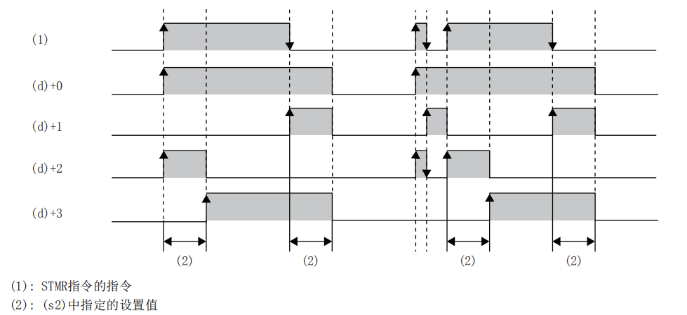
- STMR instruction instruction
- The setting value specified in (S2)
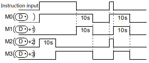
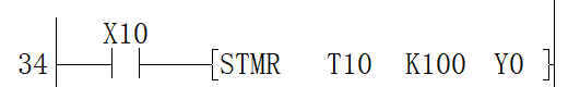
The blink will be in (d)+3 normally closed contact through the following program which turns on/off the STMR instruction (T10 is allocated in (s1), K100 is allocated in (s2), and M0 is allocated in (d)) Output to (d)+1, (d)+2.


The setting value of (S2) can be specified in the range of 1 to 32767 (1 to 3276.7 seconds).
✎Note: The timer number specified by this instruction cannot be reused with other general circuits (OUT instructions, etc.). In the case of repetition, the timer action cannot be executed correctly.
The timer specified in (S1) is regarded as a 100ms timer, starting from the rising edge of the instruction contact.
Occupy the device specified in 4 points (D) at the beginning. Be careful not to overlap with the device used for machine control.
When the instruction contact is turned off, (D), (D)+1, (D)+3 will turn off after the set time. (D) +2 and timer (S1) are reset immediately.
Error code
| Error code | Content |
| 4084H | When the value specified in (S2) is less or equal to 0 |
| 4085H | When the device specified in the read application instruction (S2) and (d) exceeds the corresponding device range |
Example
Y0: When X10 changes from Off→On, Y0=On, when X10 changes from On→Off, Y0=Off after a delay of 10 seconds.
Y1: When X10 changes from On→Off, make Y1=On output once for 10 seconds.
Y3: When X10 changes from Off to On, Y3=On after 10 seconds of delay. When X10 changes from On to Off, Y3=Off after 10 seconds of delay.
Y2: When X10 changes from Off to On, output Y2=On once for 10 seconds.
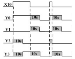
If the component (d)+3 is introduced into the instruction stream, the oscillator output can be easily realized (this function can also be realized by the ALT instruction), as shown in the following figure:

TTMR/Demonstration timer
TTMR
Test the time when the TTMR instruction is ON. It is used when adjusting the timer setting time with buttons.
-[TTMR (D) (S)]
Content, range and data type
| Parameter | Content | Range | Data type | Data type (label) |
| (D) | Device for storing teaching data | - | Signed BIN 16 bit | ANY16 |
| (S) | Multiplying ratio of teaching data | 0-2 | Signed BIN 16 bit | ANY16 |
Device used
| Instruction | Parameter | Devices | Offset modification | Pulse extension | |||||||||||
| KnX | KnY | KnM | KnS | T | C | D | R | SD | K | H | E | [D] | XXP | ||
| TTMR | Parameter 1 | ● | ● | ● | ● | ● | ● | ||||||||
| Parameter 2 | ● | ● | ● | ● | ● | ● | ● | ● | ● | ● | ● | ● | |||
Features
Measure the pressing time of the execution instruction (button) in seconds, multiply it by the magnification (10S) specified in (s) and store it in the device specified in (d).
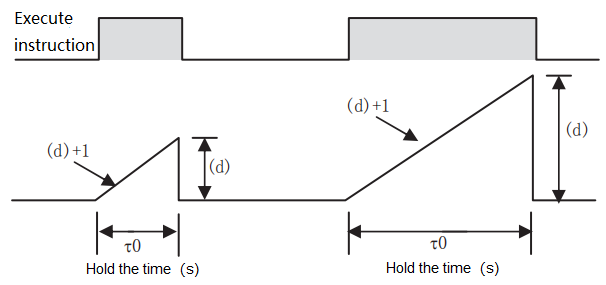
For the time stored in (d), when the hold time is
 (unit: second), the actual value of (d) is as follows according to the magnification specified in (s).
| (s) | Magnification | (D) |
| K0 | | (D) ×1 |
| K1 |  | (D)×10 |
| K2 |  | (D) ×100 |
| (s) | (d) | (d)+1 (unit: 100 milliseconds) |
| K0 (unit: second) |  | (d)+1 =(d)×10 |
| K1 (unit: 100 milliseconds) |  | (d)+1 =(d) |
| K2 (unit: 10 milliseconds) |  | (d)+1 =(d)/10 |
Occupy the device specified in the 2 teaching time (d) at the beginning. Be careful not to overlap with the device used for machine control.
Error code
| Error code | Content |
| 4084H | When the value specified in (N) exceeds the range of 0 to 2 |
| 4085H | When the device specified in read application instruction (D) and (S) exceeds the corresponding device range |
| 4086H | When the device specified in the write application instruction (D) exceeds the corresponding device range |
Example
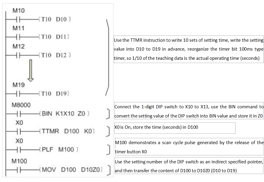
Example 1

When X0 is closed, D10=D11; when X0 is opened, the value of D10 remains unchanged, while D11 becomes 0.
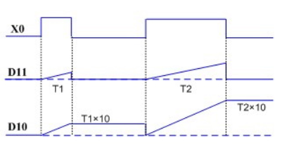
Example 2
Use the TTMR instruction to write 10 sets of setting time, write the setting value into D10 to D19 in advance, reorganize the timer bit 100ms type timer, so 1/10 of the teaching data is the actual operating time (seconds)
Connect the 1-digit DIP switch to X10 to X13, use the BIN command to convert the setting value of the DIP switch into BIN value and store it in Z0
X0 is On, store the time (seconds) in D100
M100 demonstrates a scan cycle pulse generated by the release of the timer button X0
Use the setting number of the DIP switch as an indirect specified pointer, and then transfer the content of D100 to D10Z0 (D10 to D19)
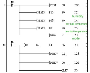
TRH/Conversion of wet and dry bulb temperature and humidity
TRH
This instruction completes the conversion of dry bulb temperature, wet bulb temperature and corresponding humidity.
-[TRH (d1) (s) (d2) (N)]
Content, range and data type
| Parameter | Content | Range | Data type | Data type (label) |
| (d1) | humidity | 0 to 100 | Single precision floating point | ANYREAL_32 |
| (s) | Dry bulb temperature | - | Single precision floating point | ANYREAL_32 |
| (d2) | Wet bulb temperature | - | Single precision floating point | ANYREAL_32 |
| (N) | mode | 0 to 1 | Signed BIN 32 bit | ANY32 |
Device used
| Instruction | Parameter | Devices | Offset modification | Pulse extension | ||||||||||
| KnX | KnY | KnM | KnS | T | C | D | R | SD | K | H | [D] | XXP | ||
| TRH | Parameter 1 | ● | ● | ● | ● | ● | ● | |||||||
| Parameter 2 | ● | ● | ● | ● | ● | ● | ||||||||
| Parameter 3 | ● | ● | ● | ● | ● | ● | ||||||||
| Parameter 4 | ● | ● | ● | ● | ● | ● | ● | ● | ● | ● | ● | ● | ||
Features
(N)There are two modes to choose from:
Mode 0: Calculate the corresponding humidity by wet bulb temperature and dry bulb temperature.
Mode 1: Calculate the corresponding wet bulb temperature by dry bulb temperature and humidity.
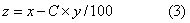
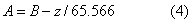
The conversion process formula is as follows:
Assuming that the wet bulb temperature is A, the dry bulb temperature is B, and the corresponding current humidity is C, the three meet the following conditions:


✎Note:
● The wet bulb temperature is not greater than the dry bulb temperature. When the two are the same, the humidity reaches the maximum 100%.
● The unit of dry and wet bulb temperature is (℃).
● The general value range of dry bulb is between 0 to 100℃, the command does not judge its range, so pay special attention when using this command.
Error code
| Error code | Content |
| 4084H | The value specified in (N) is out of the following range. 0 to 1 |
| The value specified in (d1) is out of the following range. 0 to 100 | |
| A negative value is specified in (s). | |
| A negative value is specified in (d2). | |
| 4085H | The output result of (d1)(s)(d2)(N) in the read application instruction exceeds the device range |
| 4086H | The output result of (d1)(d2) in the writing application instruction exceeds the device range |
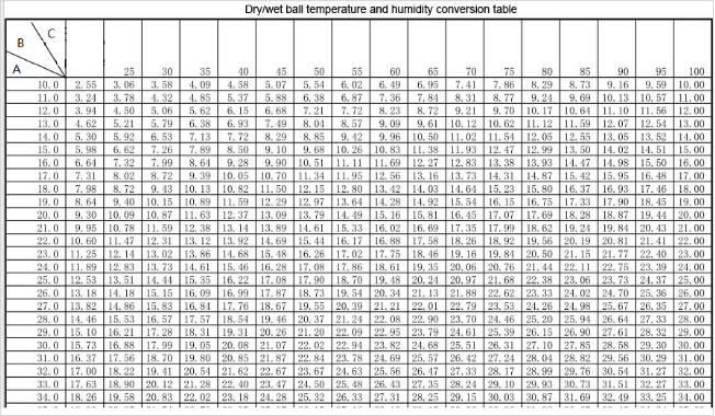
Dry and wet bulb humidity comparison table
Example
MOVAVG/BIN 32-bit moving average filtering instructions
MOVAVG
(s1) is the data to be filtered, (s2) is the set sliding average window size, (d1) saves the process data in the instruction calculation in (s2+1) double-word devices after specifying the initial device, (d2 ) is the calculation end flag, (d3) saves the filtered result.
PLC Editor2 version that supports this instruction: 2.3.1 and above
-[MOVAVG (s1) (s2) (d1) (d2) (d3)]
Content, range and data type
| Parameter | Contect | Range | Data type | Data type (label) |
| (s1) | The starting device number of the data to be filtered is stored | 0、2-126≤|(s)|<2128 | Single precision floating point | ANYREAL_32 |
| (s2) | The sliding average window size or the initial device number of the sliding average window is stored | 1~4294967295 | Un-signed BIN 32 bit | ANY32 |
| (d1) | The storage instruction calculates the starting device number of the process data storage queue (consecutively occupies (s2+1) double-word devices) | - | Signed BIN 32 bit | ANY32_ARRAY |
| (d2) | Instruction calculation end flag bit | - | Bit | ANYBIT |
| (d3) | The starting device number of the filtered result is stored | - | Single precision floating point | ANYREAL_32 |
Device used
| Instruction | Parameter | Devices | Offset modification | Pulse extension | |||||||||||||||||||||||
| X | Y | M | S | SM | T(bit) | C(bit) | LC(bit) | HSC(bit) | D.b | KnX | KnY | KnM | KnS | T | C | D | R | SD | LC | HSC | K | H | E | [D] | XXP | ||
| MOVAVG | Parameter 1 | ● | ● | ● | ● | ||||||||||||||||||||||
| Parameter 2 | ● | ● | ● | ● | ● | ||||||||||||||||||||||
| Parameter 3 | ● | ● | ● | ● | |||||||||||||||||||||||
| Parameter 4 | ● | ● | ● | ● | |||||||||||||||||||||||
| Parameter 5 | ● | ● | ● | ● | |||||||||||||||||||||||
Features
Each time this instruction is executed, the input value (s1) will be saved to the calculation process data storage queue specified by (d1+2) starting device, where (d1) specifies the double-word device to store the current write process data queue index. The number of sliding average windows used to calculate the average value is specified in (s2). When the number of input values in the process save data queue reaches the number of sliding averages in (s2), the average calculation is started, and the value specified in (d2) The calculation end flag bit is ON. Save the average value of the data queue in the process to the initial soft component specified by (d3) as the operation result.
✎Note:
The larger the setting value in (s2), the greater the hysteresis of the output result in (d3)
When the contact before the MOVAVG instruction is closed, the calculation end flag is automatically reset, and the written index
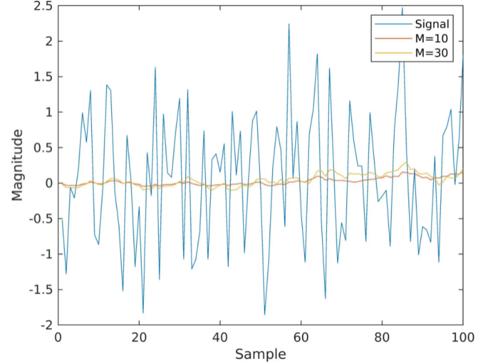
Moving average is suitable for smoothing high-frequency oscillating signals. The picture above shows the effect of the sliding average command. The blue marked high-frequency oscillation signal can be used for sliding average to obtain the yellow marked curve.
Error code
| Error code | Content |
| 4084H | The input value of (s1)(s2) in the read application instruction exceeds the data range |
| 4085H | The input value of (s1)(s2) in the read application instruction exceeds the device range |
| 4086H | The input value of (d1)(d2)(d3) in the write application instruction exceeds the device range |
Example
This instruction can be used in conjunction with the BD expansion module. When the channel value of the BD expansion module displayed in R0 is unstable, the channel value can be filtered through the following ladder diagram
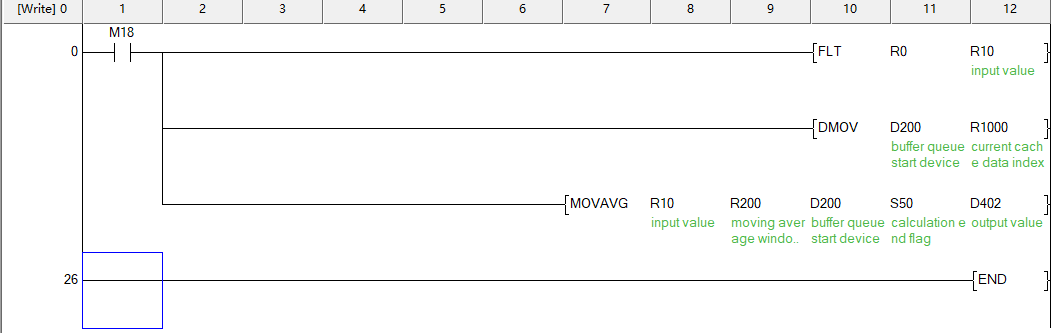
① M18 is set to ON, and the digital quantity stored in R0 is converted into a floating-point input value;
② Specify the sliding average window size in R200;
③ D200~D201 record the position index in the current write cache queue, according to the number of sliding average windows specified in R200, fill the input value in R0 into the process data cache queue with D202 as the starting device;
④ When the number of written values reaches the number specified in R200, the S50 calculation end flag will be ON, and the calculated average value will be written into the soft component specified by D402.
FOLAG/BIN 32-bit first order lag filter instruction
FOLAG
Performing first-order lag filtering on the digital signal input by (s1), and output result is stored in (d), and the filter coefficient is adjusted by (s2), and the range is (0~1).
PLC Editor2 version that supports this instruction: 2.3.1 and above
-[FOLAG (s1) (s2) (d) ]
Content, range and data type
| Parameter | Contect | Range | Data type | Data type (label) |
| (s1) | The starting device number of the data to be filtered is stored | 0、2-126≤|(s)|<2128 | Single precision floating point | ANYREAL_32 |
| (s2) | Lag filter coefficient or the initial device number where the lag filter coefficient is stored | 0~1 | Single precision floating point | ANYREAL_32 |
| (d) | The starting device number of the filtered result is stored | - | Single precision floating point | ANYREAL_32 |
Device used
| Instruction | Parameter | Devices | Offset modification | Pulse extension | |||||||||||||||||||||||
| X | Y | M | S | SM | T(bit) | C(bit) | LC(bit) | HSC(bit) | D.b | KnX | KnY | KnM | KnS | T | C | D | R | SD | LC | HSC | K | H | E | [D] | XXP | ||
| FOLAG | Parameter 1 | ● | ● | ● | ● | ||||||||||||||||||||||
| Parameter 2 | ● | ● | ● | ● | |||||||||||||||||||||||
| Parameter 3 | ● | ● | ● | ● | |||||||||||||||||||||||
Features
First order lag filter formula:
Current filtering result (d) = filtering coefficient (s2) * current input value (s1) + (1 - filtering coefficient (s2)) * last filtering result (d).
Assume that the last filtering result is 10, and the input value this time is 20, resulting in a sudden change of 10. If the first-order lag filter is used, the filter coefficient is assumed to be a = 0.05, and the filtering value this time = 0.05 * 20 + 0.95 * 10 = 10.5, which makes the sudden change less serious, and has a good effect in filtering out pulse interference. The first-order lag filter will make the obtained data waveform smoother than the original waveform. At the same time, the smaller the filter coefficient, the better the hysteresis bigger.
Error code
| Error code | Content |
| 4081H | The calculated data stored in (d) overflows |
| 4084H | The input value of (s1)(s2)(d) in the read application instruction exceeds the data range |
| 4085H | The input value of (s1)(s2)(d) in the read application instruction exceeds the device range |
Example
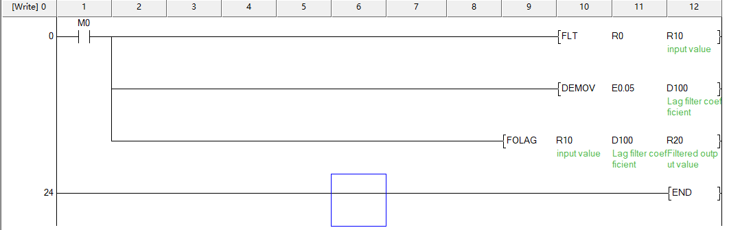
①Set M0 to ON, convert the numerical value in R0 into a floating point number and store it in R10 as the filter input value;
②Set the lag filter coefficient to 0.05 and store it in D100;③After the FOLAG instruction is executed, the filtered output value is stored in R20.
RCD/BIN 16-bit data logging instruction
RCD(P)
Store (s2) data of the start device specified in (s1), and automatically store the data in the start device specified by (s3) according to the storage number calculated in (d). Every time the instruction is enabled, ( d) It will automatically add 1, (s4) specify the maximum number that can be stored.
PLC Editor2 version that supports this instruction: 2.3.1 and above
-[RCD (s1) (s2) (s3) (s4) (d) ]
Content, range and data type
| Parameter | Contect | Range | Data type | Data type (label) |
| (s1) | Store the starting device number of the data to be recorded (occupies (s2) word devices) | - | BIN16 bit | ANY16 |
| (s2) | The number of devices that need to be recorded or the device number that stores the number of devices that need to be recorded | 1 to 65535 | Unsigned BIN16 bit | ANY16 |
| (s3) | The starting device number of data record storage (occupying (s4) words of device) | - | BIN16 bit | ANY16 |
| (s4) | The number of devices allowed to be occupied by the data record or the number of the device that stores the number of devices allowed to be occupied by the data record | 1 to 65535 | Unsigned BIN16 bit | ANY16 |
| (d) | The device number that stores the current recording times | 1 to 65535 | Unsigned BIN16 bit | ANY16 |
Device used
| Instruction | Parameter | Devices | Offset modification | Dword expansion | Pulse extension | |||||||||||||||||||||||
| X | Y | M | S | SM | T(bit) | C(bit) | LC(bit) | HSC(bit) | D.b | KnX | KnY | KnM | KnS | T | C | D | R | SD | LC | HSC | K | H | E | [D] | XXP | |||
| RCD | Parameter 1 | ● | ● | ● | ● | |||||||||||||||||||||||
| Parameter 2 | ● | ● | ● | ● | ● | ● | ||||||||||||||||||||||
| Parameter 3 | ● | ● | ● | ● | ||||||||||||||||||||||||
| Parameter 4 | ● | ● | ● | ● | ● | ● | ||||||||||||||||||||||
| Parameter 5 | ● | ● | ● | ● | ||||||||||||||||||||||||
Features
①When SM233 is ON, the loop recording function is turned on, and when the recorded data exceeds the number of devices allowed to be occupied by the setting in (s4), the recording starts from the specified device in (s3);
②When SM233 is OFF, the recorded data cannot exceed the allowed number of occupied devices set in (s4).
Error code
| Error code | Content |
| 4084H | The data in the read application instruction (s2), (s4) exceeds the specified range (s2=0, s4=0, s2>s4) |
| 4085H | When the device specified in the read application instruction (s1), (s2), (s4), and (d) exceeds the range of the corresponding device |
| 4086H | When the device occupied by the write application instruction (s3), (d) exceed the range of the corresponding device |
| 4096H | When the device in the read application instruction (s1) and (s3) are multiplexed |
Example
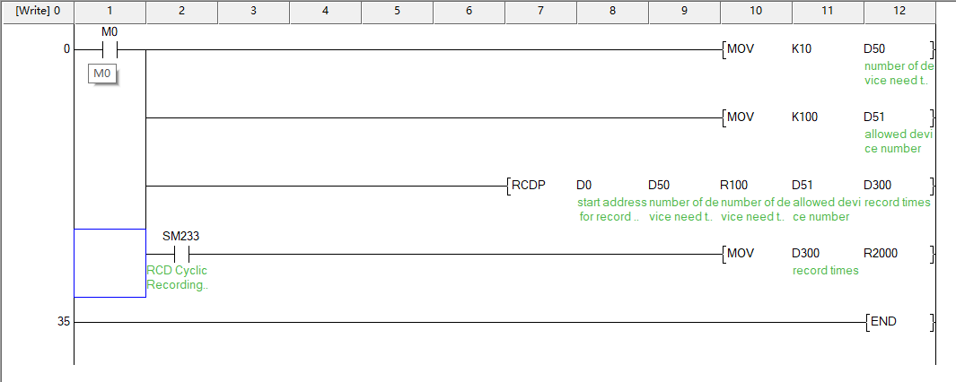
①Set M0 to ON, set the number of devices to be recorded in D50 to 10, then the number of devices to be recorded is D0~D9;
②In D51, set the record data allowed to occupy the number of device to 100, then the record data allowed to store the device as R100~R199;
③Every time a rising edge is detected, record the data in D0~D9 to the device starting from R100, and the writing position is offset according to the current recording times;
④ If SM233 is OFF, the data will be recorded within the range of the currently allowed occupied device; if SM233 is ON, then circular recording will be performed, and the recording times in D300 will be increased by 1 for each recording.