BCD/BIN → BCD
BCD(P)
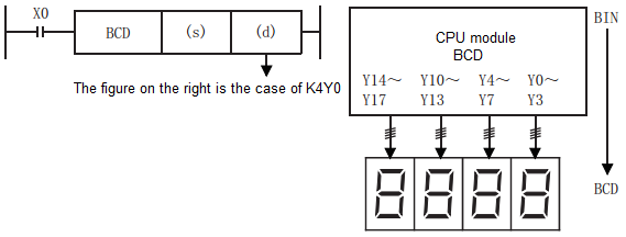
Convert the BIN data of the device specified in (s) to BCD, and store it in the device specified in (d).
The calculation of the CPU module uses BIN (binary number) data for processing, which is used to display values in a 7-segment display equipped with a BCD decoder.
-[BCD (s) (d)]
Content, range and data type
| Parameter | Content | Range | Data type | Data type (label) |
| (s) | BIN data or start device storing BIN data | 0 to 9999 | Signed BIN16 | ANY16 |
| (d) | Start device for storing BCD data | - | BCD 4 digits | ANY16 |
Device used
| Instruction | Parameter | Devices | Offset modification | Pulse extension | ||||||||||
| KnX | KnY | KnM | KnS | T | C | D | R | SD | K | H | [D] | XXP | ||
| BCD | Parameter 1 | ● | ● | ● | ● | ● | ● | ● | ● | ● | ● | ● | ● | ● |
| Parameter 2 | ● | ● | ● | ● | ● | ● | ● | ● | ● | ● | ● | ● | ||
Features
The BIN 16-bit data (0 to 9999) of the device specified in (s) is converted to BCD 4-bit data and stored in the device specified in (d).
The data specified in (s) can be converted within the range of 0 to 9999 (BCD).
When the data specified in (s) or (d) is digit specification, the conditions are as shown in the table below.
(1): Must be set to 0.

The data specified in (s) can be converted in the range of K0 to K9999 by BCD (decimal number).
When the data specified in (s) or (d) is digit specification, the conditions are as shown in the table below.
| (d) | Digits | Data range |
| K1Y0 | 1-bit | 0 to 9 |
| K2Y0 | 2-bit | 00 to 99 |
| K3Y0 | 3-bit | 000 to 999 |
| K4Y0 | 4-bit | 0000 to 9999 |
Error code
| Error code | Content |
| 4084H | The data input in the application instruction (s) exceeds the specified range |
| 4085H | The output result of the read application instruction (s) exceeds the device range |
| 4086H | The output result of the write application instruction (d) exceeds the device range |
Example
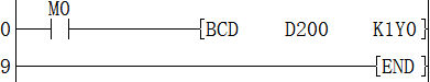
When M0 is set, the BIN value of D200 is converted into BCD and stored in K1Y0.
BIN/4-bit BCD → BIN
BIN(P)
Convert the BCD data of the device specified in (s) to BIN and store it in the device specified in (d).
Similar to the digital switch, it converts the value set in BCD (decimal number) to BIN (binary number) that can be operated by the CPU module and is used for reading.
-[BIN (s) (d)]
Content, range and data type
| Parameter | Content | Range | Data type | Data type (label) |
| (s) | BCD data or start device storing BIN data | 0 to 9999 | BCD 4 digits | ANY16 |
| (d) | Start device for storing BIN data | - | Signed BIN16 | ANY16 |
Device used
| Instruction | Parameter | Devices | Offset modification | Pulse extension | ||||||||||
| KnX | KnY | KnM | KnS | T | C | D | R | SD | K | H | [D] | XXP | ||
| BIN | Parameter 1 | ● | ● | ● | ● | ● | ● | ● | ● | ● | ● | ● | ● | ● |
| Parameter 2 | ● | ● | ● | ● | ● | ● | ● | ● | ● | ● | ||||
Features
The BCD 4-bit data (0 to 9999) of the device specified in (s) is converted into BIN 16-bit data and stored in the device specified in (d).
(1): Must become 0.

The data specified in (s) can be converted within the range of 0 to 9999 (BCD).
When the data specified in (s) or (d) is digit specification, the conditions are as shown in the table below.

| (d) | Digits | Data range |
| K1X0 | 1-bit | 0 to 9 |
| K2X0 | 2-bit | 00 to 99 |
| K3X0 | 3-bit | 000 to 999 |
| K4X0 | 4-bit | 0000 to 9999 |
Error code
| Error code | Content |
| 4084H | The data input in the application instruction (s) exceeds the specified range |
| 4085H | The output result of the read application instruction (s) exceeds the device range |
| 4086H | The output result of the write application instruction (d) exceeds the device range |
Example

When M0 is set, the BCD value of K1Y0 is converted into BIN and stored in D200.
DBIN/8-bit BCD → BIN
DBIN(P)
Convert the BCD data of the device specified in (s) to BIN and store it in the device specified in (d).
Similar to the digital switch, it converts the value set in BCD (decimal number) to BIN (binary number) that can be operated by the CPU module and is used for reading.
-[DBIN (s) (d)]
Content, range and data type
| Parameter | Content | Range | Data type | Data type (label) |
| (s) | BCD data or start device storing BIN data | 0 to 99999999 | BCD 8 digits | ANY32 |
| (d) | Start device for storing BIN data | - | Signed BIN32 | ANY32 |
Device used
| Instruction | Parameter | Devices | Offset modification | Pulse extension | ||||||||||||
| KnX | KnY | KnM | KnS | T | C | D | R | SD | LC | HSC | K | H | [D] | XXP | ||
| DBIN | Parameter 1 | ● | ● | ● | ● | ● | ● | ● | ● | ● | ● | ● | ● | ● | ● | ● |
| Parameter 2 | ● | ● | ● | ● | ● | ● | ● | ● | ● | ● | ||||||
Features
The BCD 8-bit data (0 to 99999999) of the device specified in (s) is converted to BIN 32-bit data and stored in the device specified in (d).
(1): Must become 0.

The data specified in (s) can be converted within the range of 0 to 99999999 (BCD).
When the data specified in (s) or (d) is digit specification, the conditions are as shown in the table below.

| (d) | Bit | Data range |
| K1X0 | 1-bit | 0 to 9 |
| K2X0 | 2-bit | 00 to 99 |
| K3X0 | 3-bit | 000 to 999 |
| K4X0 | 4-bit | 0000 to 9999 |
| K5X0 | 5-bit | 00000 to 99999 |
| K6X0 | 6-bit | 000000 to 999999 |
| K7X0 | 7-bit | 0000000 to 9999999 |
| K8X0 | 8-bit | 00000000 to 99999999 |
Error code
| Error code | Content |
| 4084H | The data input in the application instruction (s) exceeds the specified range |
| 4085H | The output result of the read application instruction (s) exceeds the device range |
| 4086H | The output result of the write application instruction (d) exceeds the device range |
Example

When M0 is set, the BCD value of K8Y0 is converted into BIN and stored in D200.
FLT/BIN integer → binary floating point number
FLT(P)
An instruction to convert a BIN 16-bit integer value into a binary floating point number (real number).
-[FLT (s) (d)]
Content, range and data type
| Parameter | Content | Range | Data type | Data type (label) |
| (s) | The data register number that saves the BIN integer value | - | Signed BIN 16 bit | ANY16 |
| (d) | The data register number that saves the binary floating-point number (real number) | - | Single precision real number | ANYREAL_32 |
Device used
| Instruction | Parameter | Devices | Offset modification | Pulse extension | ||||||||||||
| KnX | KnY | KnM | KnS | T | C | D | R | SD | LC | HSC | K | H | [D] | XXP | ||
| FLT | Parameter 1 | ● | ● | ● | ● | ● | ● | ● | ● | ● | ● | ● | ● | ● | ||
| Parameter 2 | ● | ● | ● | ● | ● | ● | ● | ● | ● | |||||||
Features
The signed 16-bit data specified in (s) is converted into a binary floating point data and stored in (d)+1, (d).


The inverse conversion instruction of this instruction is INT (convert a binary floating point value into a BIN integer).
Error code
| Error code | Content |
| 4085H | When the device specified in the read application instruction (s) exceeds the corresponding device range |
| 4086H | When the device specified in the write application instruction (d) exceeds the corresponding device range |
Example
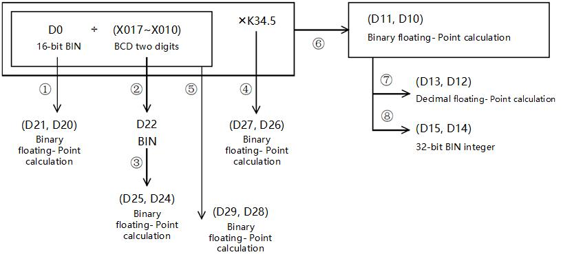
Four arithmetic using binary floating point operations
(1) Calculation example
(2) Sequence control program
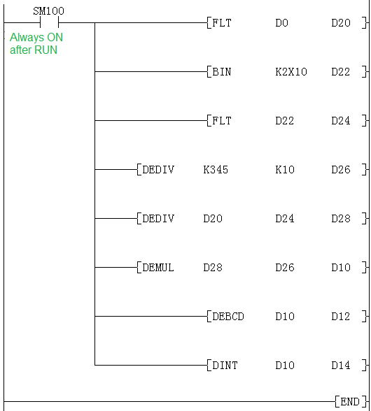
(D0) → (D21, D20)
BIN binary floating point operations
(X17 to X10) → (D22)
BCD BIN
(D22) → (D25, D24)
BIN binary floating point operations
K345÷K10 → (D27, D26)
Binary floating point operations
(D29,D28)×(D27,D26) → (D11,D10)
Binary floating-point number multiplication
(D21,D20)÷(D25,D24) → (D29,D28)
Binary floating-point number division operation →Binary floating-point number operation
(D11,D10) → (D13,D12)
Binary floating-point calculations →
Decimal floating-point calculations monitoring
(D11,D10) → (D13,D12)
Binary floating point operations 32-bit BIN integer
DFLT/BIN integer → binary floating point number
DFLT(P)
An instruction to convert a BIN 32-bit integer value into a binary floating point number (real number).
-[DFLT (s) (d)]
Content, range and data type
| Parameter | Content | Range | Data type | Data type (label) |
| (s) | The data register number that saves the BIN32 integer value | - | Signed BIN 32 bit | ANY32 |
| (d) | The data register number that saves the binary floating-point number (real number) | - | Single precision real number | ANYREAL_32 |
Device used
| Instruction | Parameter | Devices | Offset modification | Pulse extension | ||||||||||||
| KnX | KnY | KnM | KnS | T | C | D | R | SD | LC | HSC | K | H | [D] | XXP | ||
| DFLT | Parameter 1 | ● | ● | ● | ● | ● | ● | ● | ● | ● | ● | ● | ● | ● | ● | ● |
| Parameter 2 | ● | ● | ● | ● | ● | ● | ● | ● | ● | |||||||
Features
Convert the signed BIN 32-bit data specified in (s) to binary floating point data and store them in (d)+1, (d).


Error code
| Error code | Content |
| 4085H | When the device specified in the read application instruction (s) exceeds the corresponding device range |
| 4086H | When the device specified in the write application instruction (d) exceeds the corresponding device range |
Example

When M2=ON, convert the BIN 32-bit integer -7963590 in [D1, D0] into a single-precision floating point number -7963590.0 and store it in the [D101, D100] device.
VAL/ String → BIN 16-bit data conversion
VAL(P)
After converting the character string stored in the device number specified in (s) and later into BIN 16-bit data, store the number of digits in (d1) and store the BIN data in (d2).
[VAL (s) (d1) (d2)]
Content, range and data type
| Parameter | Content | Range | Data type | Data type (label) |
| (s) | The character string converted to BIN data or the start device that stores the character string | - | String | ANYSTRING_SINGLE |
| (d1) | The start device that stores the number of digits of converted BIN data | - | Signed BIN 16 bit | ANY16_S_ARRAY |
| (d2) | Start device for storing converted BIN data | - | Signed BIN 16 bit | ANY16_S |
Device used
| Instruction | Parameter | Devices | Offset modification | Pulse extension | |||||||
| KnY | KnM | KnS | T | C | D | R | SD | [D] | XXP | ||
| VAL | Parameter 1 | ● | ● | ● | ● | ● | ● | ● | |||
| Parameter 2 | ● | ● | ● | ● | ● | ● | ● | ● | ● | ● | |
| Parameter 3 | ● | ● | ● | ● | ● | ● | ● | ● | ● | ● | |
Features
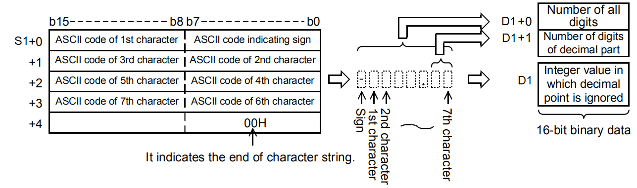
After converting the character string stored in the device number specified in (s) and later into BIN 16-bit data, store the number of digits in (d1) and store the BIN data in (d2). In the conversion from character string to BIN, the data from the device number specified in (s) to the device number storing 00H is treated as a character string.
The total number of digits stored in (d1) stores the number of all characters (including signs and decimal points) representing the value. The number of decimal places stored in (d1)+1 stores the number of characters representing the decimal part after 2EH(.). For the BIN 16-bit data stored in (d2), the character string ignoring the decimal point is converted into a BIN value and stored.
Error code
| Error code | Content |
| 4082H | The character string specified by (s) could not be converted into a numeric value For example: The first character is not a negative sign or a space, space appears in the middle of the number, decimal point appears twice. Except for the first character that appears non-characters and decimal points, the number in the symbolic string with the decimal point is removed and the range between -32768 and 32767 is exceeded Except for the first character, there are non-character and decimal Signs For example, 3.4000 is 34000 after removing the decimal point, which is out of range. |
| 4085H | (s) read address exceeds the device range |
| 408AH | When the character number of character string the specified in (s) is other than 2 to 8. |
| 408BH | The maximum range of the device is read when (s) taking character string, but 00H is not found as the end |
| 4086H | When using offset, the offset address of (d) exceeds the device range |
Example

The result obtained above:
D0 corresponds to str length is 7.
D1 corresponds to a decimal point length of 3.

D10 corresponds to -12356 ignoring the decimal point.

DVAL/String → BIN32-bit data conversion
DVAL(P)
After converting the character string stored in the device number specified in (s) into BIN 32-bit data, store the number of digits in (d1) and store the BIN data in (d2).
-[DVAL (s) (d1) (d2)]
Content, range and data type
| Parameter | Content | Range | Data type | Data type (label) |
| (s) | The character string converted to BIN data or the start device that stores the character string | - | String | ANYSTRING_SINGLE |
| (d1) | The start device that stores the number of digits of converted BIN data | - | Signed BIN 16 bit | ANY16_S_ARRAY |
| (d2) | Start device for storing converted BIN data | - | Signed BIN 32 bit | ANY32_S |
Device used
| Instruction | Parameter | Devices | Offset modification | Pulse extension | |||||||||
| KnY | KnM | KnS | T | C | D | R | SD | LC | HSC | [D] | XXP | ||
| DVAL | Parameter 1 | ● | ● | ● | ● | ● | ● | ● | |||||
| Parameter 2 | ● | ● | ● | ● | ● | ● | ● | ● | ● | ● | |||
| Parameter 3 | ● | ● | ● | ● | ● | ● | ● | ● | ● | ● | ● | ● | |
Features
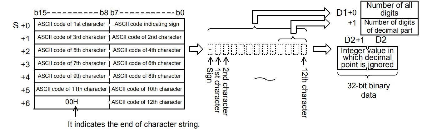
After converting the character string stored in the device number specified in (s) into BIN 32-bit data, store the number of digits in (d1) and store the BIN data in (d2). In the conversion from character string to BIN, the data from the device number specified in (s) to the device number storing 00H is treated as a character string.
The total number of digits stored in (d1) stores the number of all characters (including signs and decimal points) representing the value. The number of decimal places stored in (d1)+1 stores the number of characters representing the decimal part after 2EH(.). For the BIN 32-bit data stored in (d2), the character string ignoring the decimal point is converted into a BIN value and stored.
Error code
| Error code | Content |
| 4082H | The character string specified by (s) could not be converted into a numeric value. For example:The first character is not a negative sign or a space, space appears in the middle of the number, decimal point appears twice. Except for the first character that appears non-characters and decimal points, the number in the symbolic string with the decimal point is removed and the range between -2147483648 and 2147483647 is exceeded Except for the first character, there are non-character and decimal Signs For example, 3.000000000 is 3000000000 after removing the decimal point, which is out of range. |
| 4085H | (s) read address exceeds the device range |
| 408AH | When the character number of character string the specified in (s) is other than 2 to 13. |
| 408BH | The maximum range of the device is read when (d1) and (d2) taking character string, but 00H is not found as the end |
| 4086H | When using offset, the offset address of (d) exceeds the device range |
Example
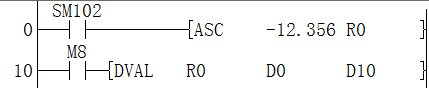
The result obtained above
D0 corresponds to str length is 7.
D1 corresponds to a decimal point length of 3.
D10 corresponds to -12356 ignoring the decimal point

ASCI/HEX code data →ASCII conversion
ASCI(P)
After the n characters (bits) in the HEX code data specified in (S) are converted into ASCII codes, they are stored after the device number specified in (D).
-[ASCI (S) (D) (N)]
Content, range and data type
| Parameter | Content | Range | Data type | Data type (label) |
| (S) | The start number of the device storing the HEX code to be converted | - | BIN16 bit | ANY16 |
| (D) | The start number of the device storing the converted ASCII code | - | String | ANYSTRING_SINGLE |
| (N) | The number of characters (digits) of the HEX code to be converted | 1to256 | BIN16 bit | ANY16_U |
Device used
| Instruction | Parameter | Devices | Offset modification | Pulse extension | |||||||||||
| KnX | KnY | KnM | KnS | T | C | D | R | SD | K | H | E | [D] | XXP | ||
| ASCI | Parameter 1 | ● | ● | ● | ● | ● | ● | ● | ● | ● | ● | ● | ● | ● | |
| Parameter 2 | ● | ● | ● | ● | ● | ● | ● | ● | ● | ● | |||||
| Parameter 3 | ● | ● | ● | ● | ● | ● | |||||||||
Features
The number of characters (bits) specified by (N) in the HEX code data specified in (S) is converted into ASCII code and stored in the device number specified in (D) or later.
ASCI(P) instruction uses 16-bit mode and 8-bit mode when converting. For the operation of each mode, please refer to the following content.
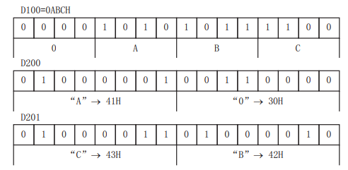
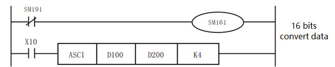
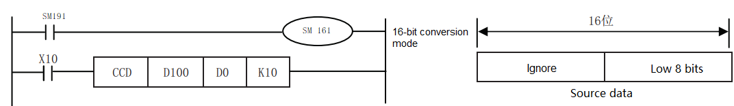
(1) 16-bit conversion mode (when SM8161=OFF)
Convert the digits of the HEX code after the device specified in (S) into ASCII, and transfer to the upper and lower 8 bits (bytes) of the device specified in (D). When using in 16-bit conversion mode, SM161 should always be turned OFF.
In the case of the following program, perform the conversion as shown below.
Specify the number of bits (characters) and the conversion result
| (N) | K1 | K2 | K3 | K4 | K5 | K6 | K7 | K8 | K9 |
| (D) | |||||||||
| Under D200 | C | B | C | 0 | 4 | 3 | 2 | 1 | 8 |
| D200 on | C | B | C | 0 | 4 | 3 | 2 | 1 | |
| Under D201 | C | B | C | 0 | 4 | 3 | 2 | ||
| D201 on | C | B | C | 0 | 4 | 3 | |||
| Under D202 | C | B | C | 0 | 4 | ||||
| D202 on | Unchanged | C | B | C | 0 | ||||
| Under D203 | C | B | C | ||||||
| D203 on | C | B | |||||||
| Under D204 | C | ||||||||
Bit structure in the case of (n)=K4
ASCII code
"0"=30H "1"=32H "5"=35H
"A"=41H "2"=32H "6"=36H
"B"=42H "3"=33H "7"=37H
"C"=43H "4"=34H "8"=38H
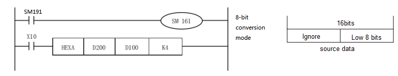
(2) 8-bit conversion mode (when SM161=ON)
Convert the digits of the HEX code after the device specified in (S) into ASCII, and transfer to the lower 8 bits (bytes) of the device specified in (D). When using in 8-bit conversion mode, SM161 should always be set to ON for use.
In the case of the following program, perform the conversion as shown below.
If SM161 is set to ON, it will become 8-bit mode,
Perform conversion processing as shown below.
| (N) | K1 | K2 | K3 | K4 | K5 | K6 | K7 | K8 | K9 |
| (D ) | |||||||||
| D200 | C | B | C | 0 | 4 | 3 | 2 | 1 | 8 |
| D201 | C | B | C | 0 | 4 | 3 | 2 | 1 | |
| D202 | C | B | C | 0 | 4 | 3 | 2 | ||
| D203 | C | B | C | 0 | 4 | 3 | |||
| D204 | C | B | C | 0 | 4 | ||||
| D205 | Unchanged | C | B | C | 0 | ||||
| D206 | C | B | C | ||||||
| D207 | C | B | |||||||
| D208 | C | ||||||||
Bit structure in the case of (N)=K2
ASCII
"0"=30H "1"=31H "5"=35H
"A"=41H "2"=32H "6"=36H
"B"=42H "3"=33H "7"=37H
"C"=43H "4"=34H "8"=38H
Error code
| Error code | Content |
| 4085H | When the specified device range is read to exceed the corresponding device range |
| 4086H | When the specified device range is written to exceed the corresponding device range |
| 4084H | When the value specified in (N) exceeds the range of 1 to 256 |
Example
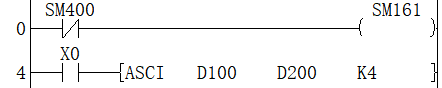
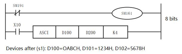
• 16-bit conversion mode (when SM161=OFF)
Convert the digits of the HEX code after the device specified in d100 into ASCII, and transfer to the upper and lower 8 bits (bytes) of the device specified in d200. When using in 16-bit conversion mode, SM161 should always be turned OFF.
HEX/ASCII → HEX code data conversion
HEX(P)
After the device number specified in (s), the ASCII data stored in the number of characters specified in (n) is converted to HEX code, and then stored in the device number specified in (d) or later.
-[HEX (S) (D) (N)]
Content, range and data type
| Parameter | Content | Range | Data type | Data type (label) |
| (S) | The start device that stores the ASCII data converted to HEX code | - | String | ANYSTRING_SINGLE |
| (D) | The start device that stores converted HEX code | - | BIN16 bit | ANY16 |
| (N) | Number of characters (bytes) of converted ASCII data | 1 to 256 | BIN16 bit | ANY16_U |
Device used
| Instruction | Parameter | Devices | Offset modification | Pulse extension | ||||||||||
| KnX | KnY | KnM | KnS | T | C | D | R | SD | K | H | [D] | XXP | ||
| HEX | Parameter 1 | ● | ● | ● | ● | ● | ● | ● | ● | ● | ● | ● | ● | ● |
| Parameter 2 | ● | ● | ● | ● | ● | ● | ● | ● | ● | ● | ||||
| Parameter 3 | ● | ● | ● | ● | ● | ● | ||||||||
Features
• After the device number specified in (S), the ASCII data stored in the number of characters specified in (N) is converted to HEX code, and then stored in the device number specified in (D) or later. The HEX(P) instruction uses 16-bit conversion mode and 8-bit conversion mode when converting. For the operation of each mode, please refer to the following content.
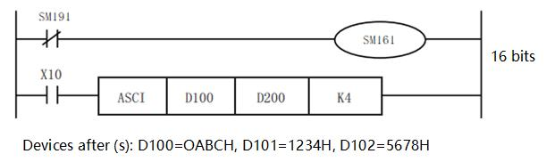
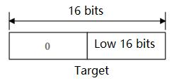
(1) 16-bit conversion mode (when SM161=OFF)
After converting the ASCII data stored in the upper and lower 8 digits (bytes) of the device specified in (S) into HEX code, it transmits every 4 digits to the device specified in (D). The number of characters to be converted is specified in (N).
SM161 is shared with ASC, ASCI, BCC, CCD and CRC instructions. When using in 16-bit conversion mode, please always set SM161 to OFF.
SM161 is cleared when RUN→STOP.
In addition, it is necessary to store the ASCII data in the 16-bit conversion mode in the upper 8 bits of the device specified in (S).
In the following program, the conversion will be performed in the following manner.
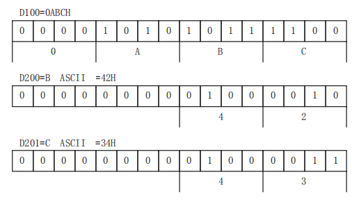
Transform the source data
| (S) | ASCII data | HEX conversion |
| Under D200 | 30H | 0 |
| D200 on | 41H | A |
| Under D201 | 42H | B |
| D201 on | 43H | C |
| Under D202 | 31H | 1 |
| D202 on | 32H | 2 |
| Under D203 | 33H | 3 |
| D203 on | 34H | 4 |
| Under D204 | 35H | 5 |
Bit structure in the case of (N)=K4

The number of characters specified and the conversion result becomes 0.
| (N) | 1 | 2 | 3 | 4 | 5 | 6 | 7 | 8 | 9 | |
| (D) | D102 | Unchanged | ...OH | |||||||
| D101 | ...OH | ..OAH | .OABH | OABCH | ABC1H | |||||
| D100 | ...OH | ..OAH | .OABH | OABCH | ABC1H | BC12H | C123H | 1234H | 2345H | |
(2) 8-bit conversion mode (when SM161=ON)
After converting the ASCII data stored in the lower 8 digits of the device specified in (S) into HEX code, it will be transmitted to the device specified in (D) every 4 digits.
The number of characters to be converted is specified in (N).
SM161 is shared with ASC, ASCI, BCC, CCD and CRC instructions. When using in 8-bit conversion mode, please always turn on SM161.
SM161 is cleared when RUN→STOP.
In the following program, the conversion will be performed in the following manner.
Transform the source data
| (S) | ASCII data | HEX conversion |
| D200 | 30H | 0 |
| D201 | 41H | A |
| D202 | 42H | B |
| D203 | 43H | C |
| D204 | 31H | 1 |
| D205 | 32H | 2 |
| D206 | 33H | 3 |
| D207 | 34H | 4 |
| D208 | 35H | 5 |
Bit structure in the case of (N)=K2

The number of characters specified and the conversion result becomes 0.
| (N) | 1 | 2 | 3 | 4 | 5 | 6 | 7 | 8 | 9 | |
| (D) | D102 | Unchanged | ...OH | |||||||
| D101 | ...OH | ..OAH | .OABH | OABCH | ABC1H | |||||
| D100 | ...OH | ..OAH | .OABH | OABCH | ABC1H | BC12H | C123H | 1234H | 2345H | |
Error code
| Error code | Content |
| 4084H | When the value specified in (N) exceeds the range. |
| When ASCII codes other than 30H to 39H and 41H to 46H are set in (s). | |
| 4085H | When the specified device range is read to exceed the corresponding device range |
| 4086H | When the specified device range is written to exceed the corresponding device range |
Example

After converting the ASCII data stored in the upper and lower 8 digits (bytes) of the device specified in (S) into HEX code, it transmits every 4 digits to the device specified in (D). The number of characters to be converted is specified in (N).
SM161 is shared with ASC, ASCI, BCC, CCD and CRC instructions. When using in 16-bit conversion mode, please always set SM161 to OFF.
CCD/Check code
CCD(P)
Calculate the horizontal parity value and the sum check value of the error checking method used in communication and the like. In addition to these error checking methods, there are CRC (Cyclic
Redundancy Check). To calculate the CRC value, use the CRC(P) command.
-[CCD (S) (D) (N)]
Content, range and data type
| Parameter | Content | Range | Data type | Data type (label) |
| (S) | The start number of object device | - | BIN16 bit | ANY16 |
| (D) | The start number of the storage destination device of the calculated data | - | BIN16 bit | ANY16_ARRAY (number of elements: 2) |
| (N) | Number of data | 1 to 256 | BIN16 bit | ANY16_U |
Device used
| Instruction | Parameter | Devices | Offset modification | Pulse extension | ||||||||||
| KnX | KnY | KnM | KnS | T | C | D | R | SD | K | H | [D] | XXP | ||
| CCD | Parameter 1 | ● | ● | ● | ● | ● | ● | ● | ● | ● | ● | ● | ||
| Parameter 2 | ● | ● | ● | ● | ● | ● | ● | ● | ● | ● | ||||
| Parameter 3 | ● | ● | ● | ● | ● | ● | ||||||||
Features
Calculate the addition data and horizontal parity data of the data stored in (S) to (S)+(N)-1, and store the addition data in (D), horizontal parity
The data is stored in (D)+1. The modes used by this instruction in calculation are 16-bit mode and 8-bit mode. For the operation of each mode, please refer to the following content.
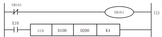
(1) 16-bit conversion mode (when SM161=OFF)
Regarding the data at point (N) starting with (S), the addition data and horizontal parity data of the high and low 8-bit data are stored in the Devicess (D) and (D)+1.
SM161 is shared with ASC, ASCI, BCC, CCD and CRC instructions. When using in 16 bits, always set to OFF for use.
SM161 is cleared when RUN→STOP.
In the case of the following program, perform the conversion as shown below.
16-bit conversion mode
If the number of 1 is odd, the horizontal parity is 1
If the number of 1 is even, the horizontal parity is 0

1091 at BCD
Horizontal parity

(2) 8-bit conversion mode (when SM161=ON)
Regarding (S) as the starting point (N) data (lower 8 bits only), its addition data and horizontal parity data are stored in the devices (D) and (D)+1.
SM161 is shared with ASC, ASCI, BCC, CCD and CRC instructions. If it is used in 8 bits, it should always be set to ON for use.
SM161 is cleared when RUN→STOP.
In the case of the following program, perform the conversion as shown below.
If the number of 1 is odd, the horizontal parity is 1
If the number of 1 is even, the horizontal parity is 0

1091 at BCD
Horizontal parity

Error code
| Error code | Content |
| 4084H | When the value specified in (N) exceed the range of 1 to 256. |
| 4085H | When the specified device range is read to exceed the corresponding device range |
| 4086H | When the specified device range is written to exceed the corresponding device range |
Example

Regarding D10 as the initial 10-point data, the addition data and horizontal parity data of the high and low 8-bit data are stored in the Devicess of D0 and D0+1.
SM161 is shared with ASC, ASCI, BCC, CCD and CRC instructions. When using in 16 bits, always set to OFF for use.
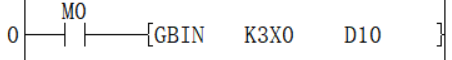
GBIN/Gray code → BIN 16-bit data conversion
GBIN(P)
Convert the BIN 16-bit Gray code data stored in the device specified in (s) into BIN 16-bit data, and store it in the device specified in (d).
-[GBIN (s) (d)]
Content, range and data type
| Parameter | Content | Range | Data type | Data type (label) |
| (s) | Gray code data or the start device that stores Gray code | 0 to 32767 | BIN16 bit | ANY16_S |
| (d) | The start device that stores the converted BIN data | - | BIN16 bit | ANY16_S |
Device used
| Instruction | Parameter | Devices | Offset modification | Pulse extension | ||||||||||
| KnX | KnY | KnM | KnS | T | C | D | R | SD | K | H | [D] | XXP | ||
| GBIN | Parameter 1 | ● | ● | ● | ● | ● | ● | ● | ● | ● | ● | ● | ● | ● |
| Parameter 2 | ● | ● | ● | ● | ● | ● | ● | ● | ● | ● | ||||
Features
Convert the BIN 16-bit Gray code data stored in the device specified in (s) into BIN 16-bit data, and store it in the device specified in (d).

GRY→BIN Mathematical Algorithm: Starting from the second bit from the left, XOR each bit with the decoded value of the left bit as the decoded value of the bit (the leftmost bit remains unchanged).
Error code
| Error code | Content |
| 4084H | When the value specified in (s) exceeds the range |
| 4085H | When the specified device range is read to exceed the range of the corresponding device |
| 4086H | When the specified device range is written to exceed the range of the corresponding device |
Example
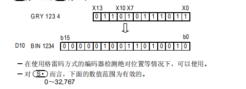
It could be used when the encoder of Gray code method is used to detect the absolute position.
For S, the numerical are valid in the range of 0 to 32767.
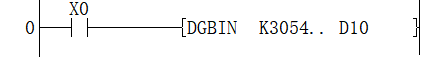
DGBIN/Gray code → BIN32-bit data conversion
DGBIN(P)
Convert the BIN32-bit Gray code data stored in the device specified in (s) to BIN 32-bit data and store it in the device specified in (d).
Content, range and data type
| Parameter | Content | Range | Data type | Data type (label) |
| (s) | Gray code data or the start device that stores Gray code | 0 to 2147483647 | BIN32 bit | ANY32_S |
| (d) | The start device that stores converted BIN data | - | BIN32 bit | ANY32_S |
Device used
| Instruction | Parameter | Devices | Offset modification | Pulse extension | ||||||||||||
| KnX | KnY | KnM | KnS | T | C | D | R | SD | LC | HSC | K | H | [D] | XXP | ||
| DGBIN | Parameter 1 | ● | ● | ● | ● | ● | ● | ● | ● | ● | ● | ● | ● | ● | ● | ● |
| Parameter 2 | ● | ● | ● | ● | ● | ● | ● | ● | ● | ● | ● | ● | ||||
Features
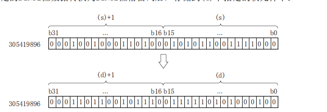
Convert the BIN32-bit Gray code data stored in the device specified in (s) into BIN 32-bit data, and store it in the device specified in (d).

(s)+1: high 16 bits
(s): low 16 bits
GRY→BIN Mathematical Algorithm: Starting from the second bit from the left, XOR each bit with the decoded value of the left bit as the decoded value of the bit (the leftmost bit remains unchanged).
Error code
| Error code | Content |
| 4084H | When the value specified in (s) exceeds the range |
| 4085H | When the specified device range is read to exceed the corresponding device range |
| 4086H | When the specified device range is written to exceed the corresponding device range |
Example
GRY/BIN 16-bit data → Gray code conversion
GRY(P)
After converting the BIN 16-bit data of the device specified in (s) to BIN 16-bit Gray code data, it is stored in the device specified in (d).
-[GRY (s) (d)]
Content, range and data type
| Parameter | Content | Range | Data type | Data type (label) |
| (s) | BIN data or the start device that stores BIN data | 0 to 32767 | BIN16 bit | ANY16_S |
| (d) | The start device that stores the converted Gray code | - | BIN16 bit | ANY16_S |
Device used
| Instruction | Parameter | Devices | Offset modification | Pulse extension | ||||||||||
| KnX | KnY | KnM | KnS | T | C | D | R | SD | K | H | [D] | XXP | ||
| GRY | Parameter 1 | ● | ● | ● | ● | ● | ● | ● | ● | ● | ● | ● | ● | ● |
| Parameter 2 | ● | ● | ● | ● | ● | ● | ● | ● | ● | ● | ||||
Features
Convert the BIN 16-bit data specified in (s) into BIN 16-bit Gray code, and store it in the device specified in (d).
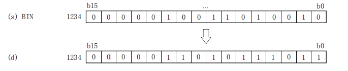
BIN→GRY Mathematical Algorithm: Starting from the rightmost bit, XOR each bit with the left bit as the value corresponding to the GRY bit, and the leftmost bit remains unchanged (equivalent to 0 on the left) .
Error code
| Error code | Content |
| 4084H | When the value specified in (s) exceeds the range |
| 4085H | When the specified device range is read to exceed the corresponding device range |
| 4086H | When the specified device range is written to exceed the corresponding device range |
Example
![]()
As shown in the above Circuit program:
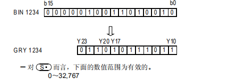
For S, the range of 0 to 32767 is valid.
DGRY/BIN 32-bit data → Gray code conversion
DGRY(P)
After converting the BIN 16-bit data of the device specified in (s) to BIN 16-bit Gray code data, it is stored in the device specified in (d).
-[GRY (s) (d)]
Content, range and data type
| Parameter | Content | Range | Data type | Data type (label) |
| (s) | BIN data or the start device that stores BIN data | 0 to 2147483647 | BIN32 bit | ANY32_S |
| (d) | The start device that stores the converted Gray code | - | BIN32 bit | ANY32_S |
Device used
| Instruction | Parameter | Devices | Offset modification | Pulse extension | ||||||||||||
| KnX | KnY | KnM | KnS | T | C | D | R | SD | LC | HSC | K | H | [D] | XXP | ||
| DGRY | Parameter 1 | ● | ● | ● | ● | ● | ● | ● | ● | ● | ● | ● | ● | ● | ● | ● |
| Parameter 2 | ● | ● | ● | ● | ● | ● | ● | ● | ● | ● | ● | ● | ||||
Features
Convert the BIN32-bit data specified in (s) into BIN32-bit Gray code and store it in the device specified in (d)
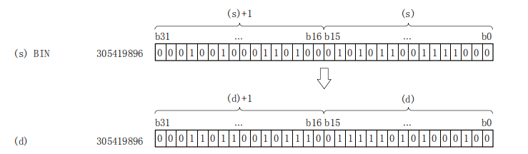
(s)+1: high 16 bits
(s): low 16 bits
BIN→GRY Mathematical Algorithm: Starting from the rightmost bit, XOR each bit with the left bit as the value corresponding to the GRY bit, and the leftmost bit remains unchanged (equivalent to 0 on the left) .
Error code
| Error code | Content |
| 4084H | When the value specified in (s) exceeds the range |
| 4085H | When the specified device range is read to exceed the corresponding device range |
| 4086H | When the specified device range is written to exceed the corresponding device range |
Example
![]()
As shown in the above Circuit program:
DPRUN/Otal digit transmission (32-bit data)
DPRUN(P)
After processing the device numbers of (s) and (d) with specified digits as octal numbers, transfer the data.
-[PRUN (s) (d)]
Content, range and data type
| Parameter | Content | Range | Data type | Data type (label) |
| (s) | Digit specification*1 | - | BIN32 bit | ANY32 |
| (d) | Transfer destination device number*1 | - | BIN32 bit | ANY32 |
Device used
| Instruction | Parameter | Devices | Offset modification | Pulse extension | ||
| KnX | KnY | KnM | [D] | XXP | ||
| DPRUN | Parameter 1 | ● | ● | ● | ● | |
| Parameter 2 | ● | ● | ● | ● | ||
Features
• Octal digit device to decimal digit device
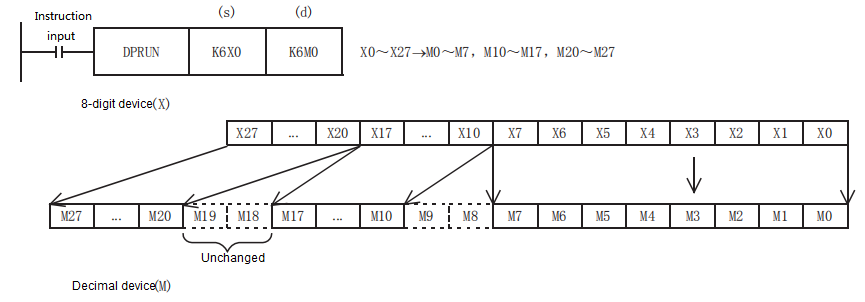
• Decimal digit device → octal digit device
Error code
| Error code | Content |
| 4085H | When the specified device range is read to exceed the corresponding device range |
| 4086H | When the specified device range is written to exceed the corresponding device range |
Example
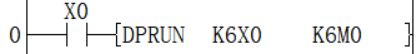
As shown in the above Circuit program:
X0 to X27 take the value of octal digits and pass them to the Devices corresponding to M.