6.2 Speed Control
Speed control refers to control the speed of the machine through the speed reference. Through internal digital setting, analog voltage or communication, the servo drive could achieve fast and precise control of the mechanical speed. Therefore, the speed control mode is mainly used to control the rotation speed, or use the host controller to realize the position control, and the host controller output is used as the speed reference, such as analog engraving and milling machine.
The speed control block diagram is as follows:

Figure1 speed control diagram
Set the parameter P0-1 to 2 through the panel or debugging tool on PC to make the servo drive work in speed control mode.
Relevant function code:
| Code | Parameter Name | Property | Effective Time | Range | Function | Unit | Default |
|---|---|---|---|---|---|---|---|
| P0-1 | Control mode (default setting) | At stop | Power-on again | 1~10 | 1: Position control mode 2: Speed control mode 3: Torque control mode | - | 1 |
Speed Reference Input Setting

Speed Reference Source
There are two sources of speed reference in speed control mode, which could be set by [P1-1].
Relevant function code:
| Code | Parameter Name | Property | Effective Time | Range | Function | Unit | Default | |
|---|---|---|---|---|---|---|---|---|
| P1-1 | Speed command source | At stop | Immediate | 0~1 | 0: Internal speed command (set in P1-3). 1: AI_1 analog input. | - | 0 | |
Internal speed reference
Set the speed value through the function code [P1-2] as the speed reference.
Relevant function codes:
| Code | Parameter Name | Property | Effective Time | Range | Function | Unit | Default |
|---|---|---|---|---|---|---|---|
| P1-2 | Internal speed command | During running | Immediate | -3000~3000 | Internal speed command | rpm | 100 |
Analog voltage input as a reference
Take the analog voltage signal output by the host controller or other equipments, processed as a speed reference.
Analog voltage setting method:

Figure 2 flowchart of setting speed reference by analog voltage
Glossary:
Zero drift: Value of the servo drive sampling voltage relative to GND when the input
voltage of the analog channel is zero.
Offset: Input voltage value of the analog channel when the sampling voltage is zero after
zero drift correction.
Dead zone: Input voltage range of the analog channel when the sampling voltage is zero.

Figure 3 Analog signal after-offset
After completing the correct settings, you could view the input voltage values of AI_1 and AI_2 through U0-21 and U0-22
| Code | Function | Unit | Format |
|---|---|---|---|
| U0-21 | AI1 input voltage value | V | decimal(3 decimal digits) |
| U0-22 | AI2 input voltage value | V | decimal(3 decimal digits) |
Relevant function codes:
| Code | Parameter Name | Property | Effective Time | Range | Function | Unit | Default |
|---|---|---|---|---|---|---|---|
| P5-1 | AI_1 input bias | During running | Immediate | -5000~5000 | Set AI_1 channel analog offset value | mv | 0 |
| P5-2 | AI_1 Input filter constant | During running | Immediate | 0~65535 | AI_1 channel input first-order low-pass filtering time constant | ms | 200 |
| P5-3 | AI_1 dead zone | During running | Immediate | 0~1000 | Set AI_1 channel analog dead zone value | mv | 20 |
| P5-4 | AI_1 zero drift | During running | Immediate | -500~500 | Automatic calibration zero drift inside the driver. | mv | 0 |
| P5-5 | AI_2 input bias | During running | Immediate | -5000~5000 | Set AI_2 channel analog offset value | mv | 0 |
| P5-6 | AI_2 Input filter constant | During running | Immediate | 0~60000 | AI_2 channel input first-order low-pass filtering time constant | ms | 200 |
| P5-7 | AI_2 dead zone | During running | Immediate | 0~1000 | Set AI_1 channel analog dead zone value | mv | 20 |
| P5-8 | AI_2 zero drift | During running | Immediate | -500~500 | Automatic calibration zero drift value inside the driver | mv | 0 |
| P5-9 | Analog 10V for speed value | At stop | Immediate | 1000~4500 | Set the speed value corresponding to analog 10V | rpm | 3000 |
| P5-10 | Analog 10V for torque value | At stop | Immediate | 0~3000 | Set the torque value corresponding to analog 10V | 0.1% | 1000 |
Acceleration and deceleration time setting
The acceleration/deceleration time setting refers to convert a speed command with a relatively high acceleration into a speed command with a relatively gentle acceleration, so as to achieve the purpose of controlling the acceleration.
In the speed control mode, excessive acceleration of the speed command would cause the vibration. At this time, increase the acceleration or deceleration time to achieve a smooth speed change of the motor and avoid mechanical damage caused by the above situation.

Figure 4 diagram of acc. and dec. time
Actual acceleration time T1 = speed reference / 1000 * acceleration time
Actual deceleration time T2 = speed reference / 1000 * deceleration time
Relevant function codes:
| Code | Parameter Name | Property | Effective Time | Range | Function | Unit | Default |
|---|---|---|---|---|---|---|---|
| P1-3 | Acc. time | During running | Immediate | 0~65535 | Acceleration time from 0 to 1000rpm in speed command mode | ms | 50 |
| P1-4 | Dec. time | During running | Immediate | 0~65535 | Deceleration time from 1000 to 0 rpm in speed command mode | ms | 50 |
Speed Reference Limitation
The servo drive could display the value of the speed reference in speed mode.
Sources of speed instruction limits include:
[P1-10]: Set the maximum speed limit value
[P1-12]: Set forward speed limit value
[P1-13]: Set the reverse speed limit value
Maximum motor speed: determined according to the model of the motor
| The amplitude of the forward speed reference | ≤ min {Max. motor speed, P1-10, P1-12}
| The amplitude of the negative speed reference | ≤ min {Max. speed of the motor, P1-10, P1-13}
Relevant function codes:
| Code | Parameter Name | Property | Effective Time | Range | Function | Unit | Default |
|---|---|---|---|---|---|---|---|
| P1-10 | Max speed threshold | During running | Immediate | 0~5000 | Set the maximum speed limit value. | rpm | 3600 |
| P1-12 | Forward speed threshold | During running | Immediate | 0~3000 | Set forward speed limit | rpm | 3000 |
| P1-13 | Reverse speed threshold | During running | Immediate | 0~3000 | Set reverse speed limit | rpm | 3000 |
6.3.4 Zero Speed Clamp Function
Zero speed clamping function means that when the zero speed clamping signal (ZCLAMP) is valid, when the absolute value of the speed reference is lower than the zero speed clamping speed value, the servo motor is in the locked state. At this time, the servo drive is in position lock mode, and the speed reference is invalid.
Relevant function codes:
| Code | Parameter Name | Property | Effective Time | Range | Function | Unit | Default |
|---|---|---|---|---|---|---|---|
| P1-21 | Zero speed clamp function selection | During running | Immediate | 0~3 | Set the zero speed clamp function. In speed mode: 0: Force speed to 0. 1: Force the speed to 0, and keep the position locked when the actual speed is less than [P1.22]. 2: When the speed reference is less than [P1-22], force the speed to 0 and keep the position locked. 3: Invalid, ignore the zero speed clamp input. | - | 0 |
| P1-22 | Speed threshold for zero | During running | Immediate | 0~1000 | Set the speed threshold of the zero speed clamp function | rpm | 20 |

Figure 5 Zero Speed Clamp waveform
Speed-relevant DO Signals
Different DO signals are output to the host controller based on comparison between the speed feedback after filter and different thresholds. We need to assign different function for the DO terminals and set the valid logic.
Motor Rotation DO Signal
After the speed reference is filtered, the absolute value of the actual speed of the servo motor reaches [P5-16] (rotation detection speed threshold), then the motor is considered to be rotating. At this time, the DO terminal of the servo drive could output a rotation detection signal. Conversely, when the actual rotation speed of the servo motor does not reach [P5-16], it is considered that the motor is not rotating.
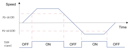
Figure 6-14 motor rotation DO signal
Relevant function codes:
| Code | Parameter Name | Property | Effective Time | Range | Function | Unit | Default |
|---|---|---|---|---|---|---|---|
| P5-16 | Rotation detection speed threshold | During running | Immediate | 0~1000 | Set motor rotation signal judgment threshold | rpm | 20 |
| P6-26 | DO_1 function selection | During running | Immediate | 128~142 | 132-TGON rotation detection | - | 131 |
Zero speed signal
The absolute value of the actual speed of the servo motor is less than a certain threshold [P5-19], it is considered that the servo motor stops rotating, and the DO terminal of the servo drive could output a zero speed signal at this time. Conversely, if the absolute value of the actual speed of the servo motor is not less than this value, it is considered that the motor is not at a standstill and the zero speed signal is invalid.

Figure 6 zero speed signal waveform
Relevant function codes:
| Code | Parameter Name | Property | Effective Time | Range | Function | Unit | Default |
|---|---|---|---|---|---|---|---|
| P5-19 | Zero speed output signal threshold | During running | Immediate | 0~6000 | Zero speed output signal threshold | rpm | 10 |
| P7-18 | DO_1 function selection | During running | Power on again | 128~142 | 133-ZSP zero speed signal | - | 132 |
Speed Consistent DO Signal
In speed control, when the absolute value of the difference between the motor speed after filter and the speed reference satisfies the setting of [P5-17], the actual motor speed is considered to reach the speed reference. At this moment, the servo drive outputs the speed consistent signal. When the absolute value of the difference between the motor speed after filter and the speed reference exceeds the setting of [P5-17], the speed consistent signal is inactive.

Figure 7 Speed Consistent Waveform
Relevant function codes:
| Code | Parameter Name | Property | Effective Time | Range | Function | Unit | Default |
|---|---|---|---|---|---|---|---|
| P5-17 | Speed consistent signal threshold | During running | Immediate | 0~100 | Set the speed consistent signal threshold | rpm | 10 |
| P7-18 | DO_1 function selection | During running | Immediate | 128~142 | 135-V-COIN speed consistent | - | 135 |
Speed Reached DO Signal
When the absolute value of the motor speed after filter exceeds the setting of[P4-16],the motor speed is considered to reach the desired value. At this moment, the servo drive outputs the speed reached signal. When the absolute value of the motor speed after filter is smaller than or equal to the setting of[P4-16], the speed reached signal is inactive.

Figure 6-17 Speed reached signal waveform
Relevant function codes:
| Code | Parameter Name | Property | Effective Time | Range | Function | Unit | Default |
|---|---|---|---|---|---|---|---|
| P5-18 | Speed approaching signal threshold | During running | Immediate | 10~6000 | Speed reached signal threshhold | rpm | 100 |
| P7-18 | DO_1 function selection | During running | Power on again | 128~142 | 136-V-NEAR speed near | - | 136 |