Main Circuit Wiring
Main Circuit Terminals
(1) Main circuit terminal distribution of VD3E type A servo drive

Figure 4-1 VD3E Type A Servo Drive Main Circuit Terminal Schematic
| Table 4-1 Name and function of main circuit terminal of VD3E type A servo drive | ||
|---|---|---|
| Terminal number | Terminal name | Terminal function |
| L1 | Power input terminal | Single-phase 220V AC input is connected to L1 and L3. |
| L2 | ||
| L3 | ||
| P+ | Braking resistor terminal | Use internal braking resistor: short connected C-D. Use an external braking resistor: please disconnect the short wire between C-D, and then connect the external braking resistor between P+ and C; |
| C | ||
| D | ||
| U | Motor power line terminal | Connect with the U, V, W of the motor to supply power to the motor. |
| V | ||
| W | ||
| Ground terminal | Ground terminal | Grounding of the servo drive. |
(2) Main circuit terminal distribution of VD3E type B servo drive (220V)

Figure 4-2 Schematic Diagram of VD3E Type B Servo Drive Main Circuit Terminal
| Table 4-2 Name and function of main circuit terminal of VD3E type B servo drive | ||
|---|---|---|
| Terminal number | Terminal name | Terminal function |
| L1 | Power input terminal | Single-phase 220V AC input is connected to L1 and L3. Three-phase 220V AC input is connected to L1, L2, L3; |
| L2 | ||
| L3 | ||
| L1C | Control power input terminal | Single-phase 220V AC input connected to L1C and L2C |
| L1C | ||
| P+ | Braking resistor terminal | Use internal braking resistor: short connected C-D. Use an external braking resistor: please disconnect the short wire between C-D, and then connect the external braking resistor between P+ and C; |
| C | ||
| D | ||
| U | Motor power line terminal | Connect with the U, V, W of the motor to supply power to the motor. |
| V | ||
| W | ||
| Ground terminal | Ground terminal | Grounding of the servo drive. |
(3) Main circuit terminal distribution of VD3E type B servo drive (380V)
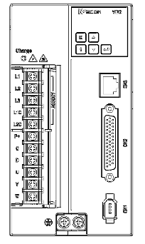
Figure 4-3 Schematic diagram of main circuit terminals of VD3E Type B servo drive (380V)
| Table 4-3 Name and function of main circuit terminal of VD3E type B servo drive | ||
|---|---|---|
| Terminal number | Terminal name | Terminal function |
| L1 | Power input terminal | Three-phase 220V AC input is connected to L1, L2, L3; |
| L2 | ||
| L3 | ||
| L1C | Control power input terminal | Single-phase 220V AC input connected to L1C and L2C |
| L1C | ||
| P+ | Braking resistor terminal | Use internal braking resistor: short connected C-D. Use an external braking resistor: please disconnect the short wire between C-D, and then connect the external braking resistor between P+ and C; |
| C | ||
| D | ||
| U | Motor power line terminal | Connect with the U, V, W of the motor to supply power to the motor. |
| V | ||
| W | ||
| Ground terminal | Ground terminal | Grounding of the servo drive. |
(4) Main circuit terminal distribution of VD3E type C servo drive (380V)
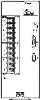
Figure 4-4 Schematic diagram of main circuit terminals of VD3E Type C servo drive (380V)
| Table 4-4 Name and function of main circuit terminal of VD3E type C servo drive | ||
|---|---|---|
| Terminal number | Terminal name | Terminal function |
| L1 | Power input terminal | Three-phase 220V AC input is connected to L1, L2, L3; |
| L2 | ||
| L3 | ||
| L1C | Control power input terminal | Single-phase 220V AC input connected to L1C and L2C |
| L1C | ||
| P+ | Braking resistor terminal | Use internal braking resistor: short connected C-D. Use an external braking resistor: please disconnect the short wire between C-D, and then connect the external braking resistor between P+ and C; |
| C | ||
| D | ||
| U | Motor power line terminal | Connect with the U, V, W of the motor to supply power to the motor. |
| V | ||
| W | ||
| Ground terminal | Ground terminal | Grounding of the servo drive. |
Power Wiring Example
(1) VD3E Type A Drive Single-phase 220V Main Circuit Wiring
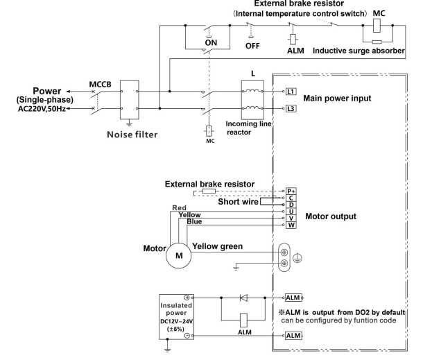
Figure 4-5 VD3E Type A Drive Single-phase 220V Main Circuit Wiring
(2) VD3E Type B Drive Single-phase 220V Main Circuit Wiring
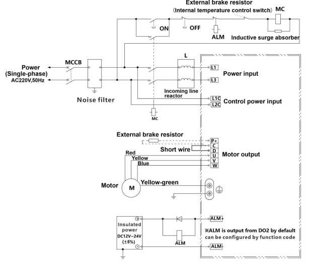
Figure 4-6 VD3E Type B Drive Single-phase 220V Main Circuit Wiring
(3) VD3E Type B Drive Three-phase 220V Main Circuit Wiring

Figure 4-7 VD3E Type B Drive Three-phase 220V Main Circuit Wiring
(4) VD3E Type B Drive Three-phase 380V Main Circuit Wiring
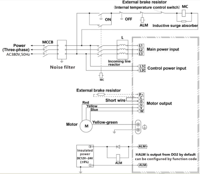
Figure 4-8 VD3E Type B Drive Three-phase 380V Main Circuit Wiring
(5) VD3E Type C Drive Three-phase 380V Main Circuit Wiring
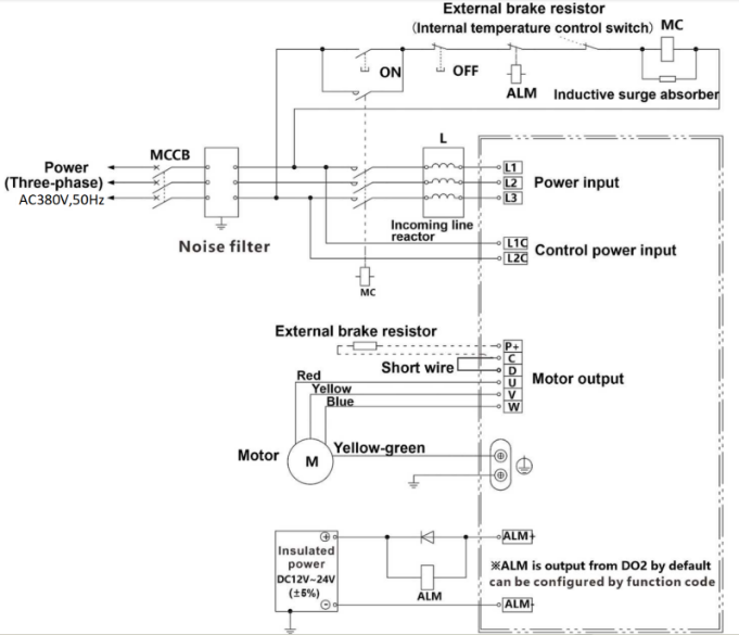
Figure 4-9 VD3E Type C Drive Three-phase 380V Main Circuit Wiring
Precautions for Main Circuit Wiring
① The input power line cannot be connected to the output terminals U, V and W, otherwise the servo drive will be damaged. When using the built-in braking resistor, C and D must be connected (factory default connection).
② When the cables are bundled and used in pipes, etc., due to the deterioration of heat dissipation conditions, please consider the allowable current reduction rate.
③ When the temperature in the cabinet is higher than the cable temperature limit, please choose a cable with a larger cable temperature limit, and it is recommended that the cable wire use Teflon wire. Please pay attention to the warmth of the cable in the low temperature environment. Generally, the surface of the cable is prone to hardening and breakage under the low temperature environment.
④ The bending radius of the cable should be more than 10 times the outer diameter of the cable itself to prevent the core of the cable from breaking due to long-term bending.
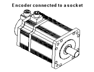
Power Line Connection of Servo Drive and Servo Motor
Power Cable
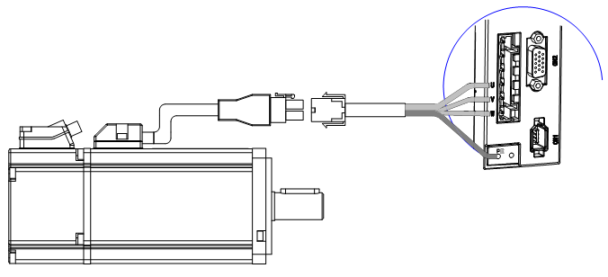
Figure 4-10 Connection schematic diagram of servo drive and servo motor
Wecon VD3E series servo drives have 3 kinds of interface power cables: rectangular plug, aviation plug and in-line type.
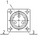
| Table 4-5 Power cable servo motor side connector | ||||||||||||||||||
|---|---|---|---|---|---|---|---|---|---|---|---|---|---|---|---|---|---|---|
| Connector exterior | Terminal pin distribution | Pin description | Adaptation Motor flange | |||||||||||||||
|
| Rectangular plug
| 60 80 | |||||||||||||||
|
| Aviation plug
| 110 130 | |||||||||||||||
|
| In-line type plug
| 60 80 | |||||||||||||||


Brake Device Cable
| Connector shape and terminal pin distribution | Pin description | ||||||||
|
|
| Connector shape and terminal pin distribution | Pin description | Adaptable motor flange | |||||||||
| WD Series |
|
| 60 80 | ||||||||
| WE Series |
|
| 80 110 130 | ||||||||

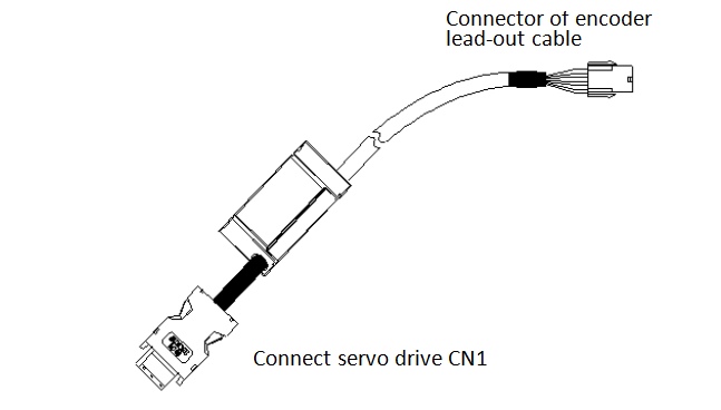
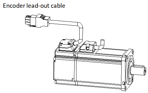
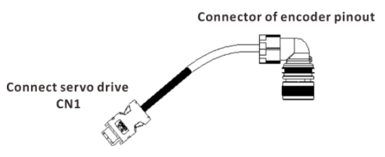
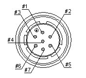
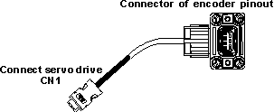
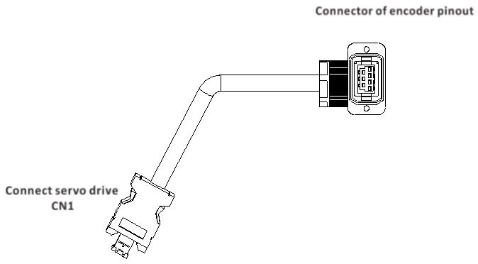
Encoder Cable Connection of Servo Drive and Servo Motor
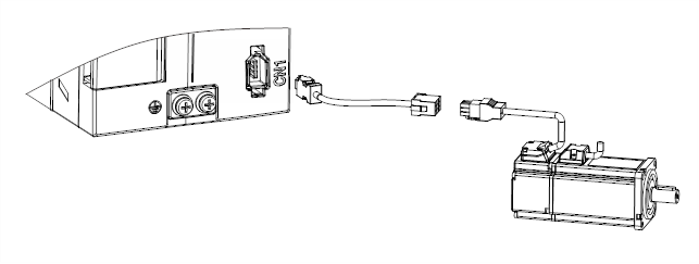
Figure 4-11 Encoder cable connection schema
| Table 4-6 Encoder cable servo drive side connector | ||||||||||||||||
|---|---|---|---|---|---|---|---|---|---|---|---|---|---|---|---|---|
| Connector exterior | Terminal pin distribution | Pin description | ||||||||||||||
|
|
| ||||||||||||||


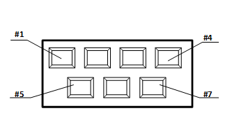
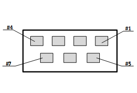
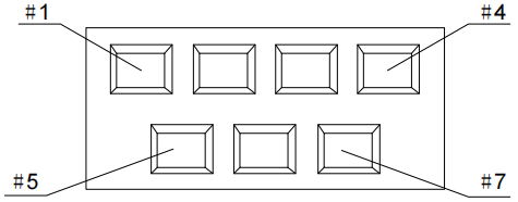
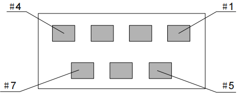
| Table 4-7 Absolute encoder cable connector (rectangular plug) | |||||||||||||||||
|---|---|---|---|---|---|---|---|---|---|---|---|---|---|---|---|---|---|
| Connector shape and terminal pin distribution | Adapted motor Flange | ||||||||||||||||
 |  | 60 80 | |||||||||||||||
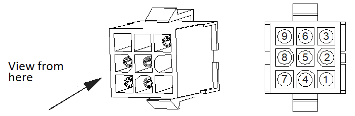 |  | ||||||||||||||||
|
| Table 4-8 Encoder cable pin connection relationship | ||||
|---|---|---|---|---|
| Drive side J1394 | Description | Motor side | ||
| Pin number | Signal name | Rectangular plug pin number | Cable color | |
| 1 | 5V | Encoder +5v power | 7 | Blue |
| 2 | GND | Encoder power ground | 8 | Orange |
| 5 | SD+ | Serial communication signal + | 4 | Green |
| 6 | SD- | Serial communication signal - | 5 | Brown |
| Shell | Shield | Shield | 3 | - |
| - | - | Battery+ | 1* | Pink |
| - | - | Battery- | 2* | Pink-Black |
The pin with “*” indicates the signal line of encoder battery. If the multi-turn battery memory function is not used, you don’t need to connect the signal lines. It is only used as single turn encoder line at this time.
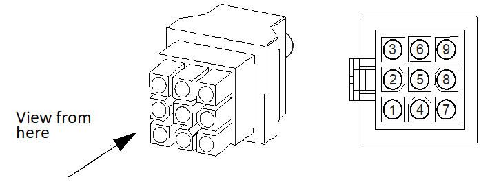
| Table 4-9 Absolute value encoder cable connector (aviation plug) | |||||||||||||||||
|---|---|---|---|---|---|---|---|---|---|---|---|---|---|---|---|---|---|
| Connector shape and terminal pin distribution | Adapted motor Flange | ||||||||||||||||
 |  | 110 130 | |||||||||||||||
|
| ||||||||||||||||
| |||||||||||||||||

| Table 4-10 Encoder cable pin connection relationship | ||||
|---|---|---|---|---|
| Drive side J1394 | Description | Motor side | ||
| Pin number | Signal name | Aviation plug pin number | Cable color | |
| 1 | 5V | Encoder +5v power | 7 | Blue |
| 2 | GND | Encoder power ground | 5 | Orange |
| 5 | SD+ | Serial communication signal + | 6 | Green |
| 6 | SD- | Serial communication signal - | 4 | Brown |
| Shell | Shield | Shield | 1 | - |
| - | - | Battery+ | 3* | Pink |
| - | - | Battery- | 2* | Pink-Black |
The pin with “*” indicates the signal line of encoder battery. If the multi-turn battery memory function is not used, you don’t need to connect the signal lines. It is only used as single turn encoder line at this time.
| Table 4-11 Absolute value encoder cable connector L type (in-line type) | |||||||||||||||||
|---|---|---|---|---|---|---|---|---|---|---|---|---|---|---|---|---|---|
| Connector shape and terminal pin distribution | Adapted motor Flange | ||||||||||||||||
|  | 60 80 | |||||||||||||||
|
| ||||||||||||||||
| |||||||||||||||||
| Table 4-12 Encoder cable pin connection relationship | ||||
|---|---|---|---|---|
| Drive side J1394 | Description | Motor side | ||
| Pin number | Signal name | Aviation plug pin number | Cable color | |
| 1 | 5V | Encoder +5v power | 7 | Blue |
| 2 | GND | Encoder power ground | 5 | Orange |
| 5 | SD+ | Serial communication signal + | 6 | Green |
| 6 | SD- | Serial communication signal - | 4 | Brown |
| Shell | Shield | Shield | 1 | - |
| -- | -- | Battery+ | 3* | Brown |
| -- | -- | Battery- | 2* | Black |
| Table 4-13 Absolute value encoder cable connector L2 type (in-line type) | |||||||||||||||||
|---|---|---|---|---|---|---|---|---|---|---|---|---|---|---|---|---|---|
| Connector shape and terminal pin distribution | Adapted motor flange | ||||||||||||||||
 |  | 60 80 | |||||||||||||||
  |  | ||||||||||||||||
|
| Table 4-14 Encoder cable pin connection relationship | |||||
|---|---|---|---|---|---|
| Drive side J1394 | Description | Motor side | |||
| Pin number | Signal name | Aviation plug pin number | Cable color | ||
| 1 | 5V | Encoder +5v power | 1 | White | |
| 2 | GND | Encoder power ground | 2 | Brown | |
| 5 | SD+ | Serial communication signal + | 3 | Green | |
| 6 | SD- | Serial communication signal - | 4 | Yellow | |
| Shell | Shield | Shield | 5 | - | |
| -- | -- | Battery+ | 6* | Pink | |
| -- | -- | Battery- | 7* | Black | |
Servo Drive Control Input and Output Terminal Wiring
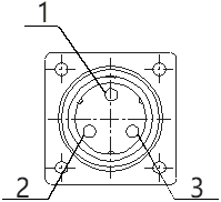
CN2 Pin Distribution
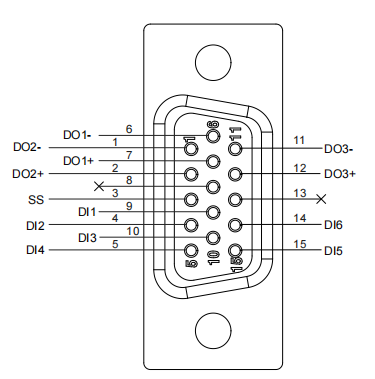
Figure 4-12 VD3E servo driver control input and output pin distribution
| Table 4-15 CN2 Interface Definition | |||
|---|---|---|---|
| Pin number | Signal name | Pin number | Signal name |
| 1 | DO2- | 9 | DI1 |
| 2 | DO2+ | 10 | DI3 |
| 3 | SS | 11 | DO3- |
| 4 | DI2 | 12 | DO3+ |
| 5 | DI4 | 13 | - |
| 6 | DO1- | 14 | DI6 |
| 7 | DO1+ | 15 | DI5 |
| 8 | - | ||
Digital Input and Output Signals
| Table 4-16 DI/DO signal description | ||
|---|---|---|
| Pin number | Signal name | Default function |
| 9 | DI1 | None |
| 4 | DI2 | Fault and warning clear |
| 10 | DI3 | Forward drive prohibition |
| 5 | DI4 | Reverse drive prohibition |
| 15 | DI5 | None |
| 14 | DI6 | None |
| 3 | SS | Power input (12 ~ 24V) |
| 6 | DO1- | Rotation detection |
| 7 | DO1+ | |
| 1 | DO2- | Fault signal |
| 2 | DO2+ | |
| 11 | DO3- | Servo ready |
| 12 | DO3+ | |
1) Digital input circuit
Taking DI1 as an example, the interface circuits of DI1 ~ DI6 are exactly the same.
When the control device(HMI/PLC) is relay output
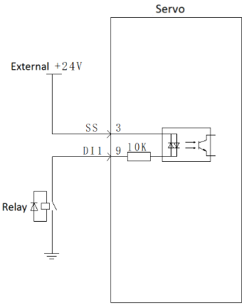
Figure 4-13 Relay output
When the control device(HMI/PLC) is open collector output
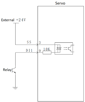
Figure 4-14 Open collector output
Digital output circuit
Taking DO1 as an example, the interface circuits of DO1 ~ DO3 are exactly the same.
When the control device(HMI/PLC) is relay input
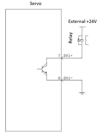
Figure 4-15 Relay input
When the control device(HMI/PLC) is optocoupler input
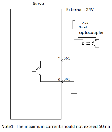
Figure 4-16 Optocoupler input
Brake Wiring
The brake is a mechanism that prevents the servo motor shaft from moving when the servo drive is in a non-operating state, and keeps the motor locked in position, so that the moving part of the machine will not move due to its own weight or external force.
The brake input signal is non-polar, and the user needs to prepare 24V power supply. The standard connection diagram of brake signal BK and brake power supply is as follows:
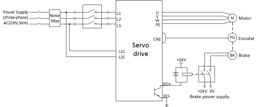
Figure 4-17 VD3E brake wiring diagram
Communication Signal Wiring
The CN5 port of the first servo drive is connected to Wecon PLC LX6V
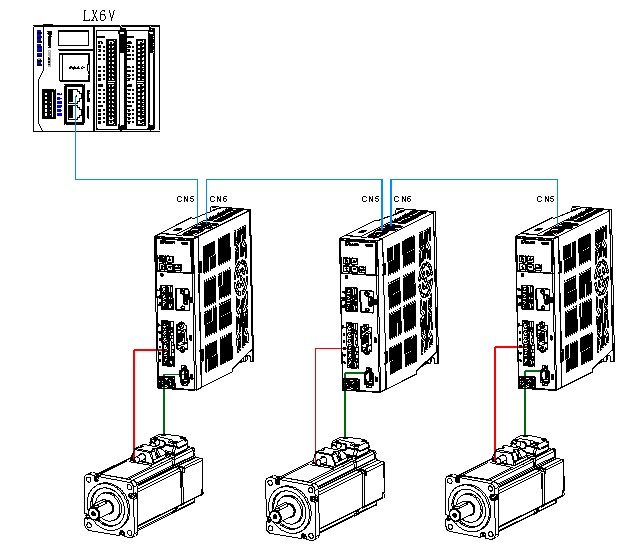
Figure 4-18 Communication topology networking schema
| Table 4-17 CN5\ CN6 interface definition | ||
|---|---|---|
| Pin | Name | Function description |
| 1 | RX- | Computer sends negative terminal (drive receives negative) |
| 2 | RX+ | Computer sends terminal (drive receives positive) |
| 3 | TX- | Computer receives negative terminal (drive sends negative) |
| 4 | GND | Ground terminal |
| 5 | Not used | Not used |
| 6 | TX+ | Computer receives positive terminal (drive sends positive) |
| 7 | - | - |
| 8 | - | - |