06 Communication Network Configuration
EtherCAT Operation
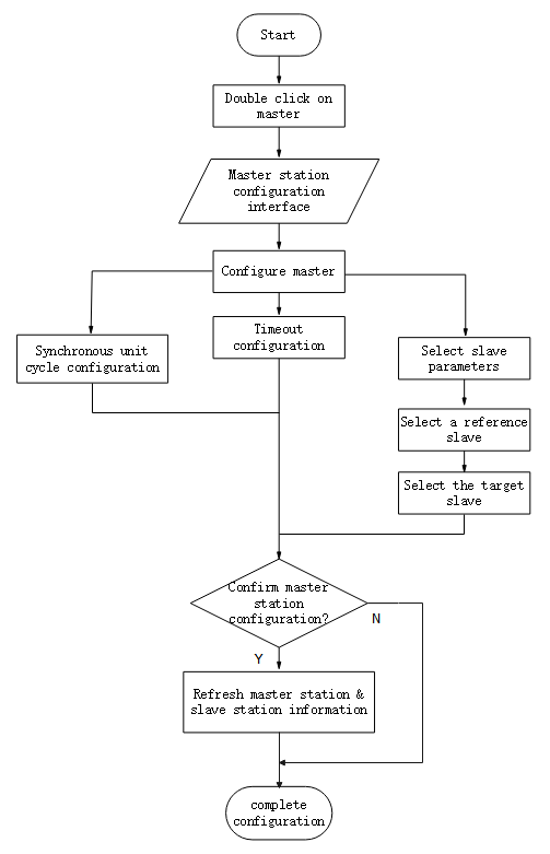
Figure 6-1 EtherCAT Operation Configuration Flow
EtherCAT Communication Fundamentals
EtherCAT Communication Specifications
| Hierarchy | Content | Specification |
|---|---|---|
| Application layer | PDO | Variable PDO mapping |
| SDO | SDO request, SDO reply | |
| CIA 402 | Cyclic Synchronous Position Mode(CSP) Origin return mode (HM) | |
| Physical layer | Transport protocol | 100BASE-TX (IEEE802.3) |
| Communication interface | RJ45 Port * 2 (IN, OUT) |
Communication Structure
Wecon VD3E series bus servo drives adopt IEC 61800-7 (CiA402)-CANOpen motion control sub-protocol.
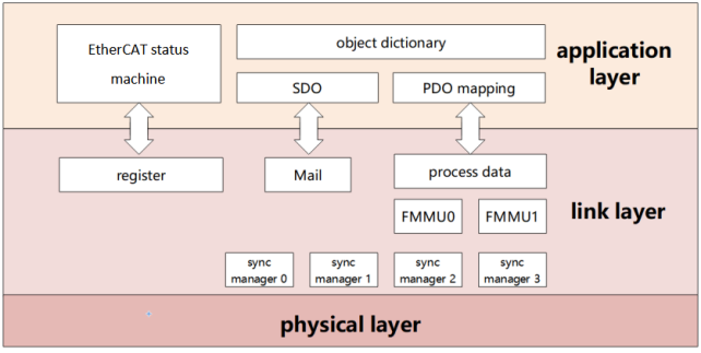
Figure 6-2 Communication structure
PDO (Process Data Object) is composed of Object Dictionary (Object Dictionary) which can be mapped in PDO, and the content of process data is defined according to PDO mapping.
Email is a kind of aperiodic communication and can read and write all object dictionaries.
State Machine
EtherCAT devices support four states and are responsible for coordinating the state relationship between master and slave applications at initialization and running:
Init: Initialization, abbreviated as I;
Pre-Operational: Pre-Operational, abbreviated as P;
Safe-Operational: Safe operation, abbreviated as S;
Operational: Operational, abbreviated as O.
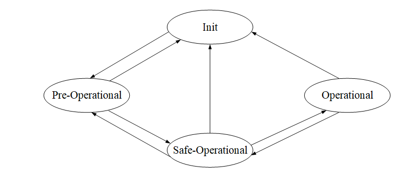
Figure 6-3 Communication structure
When changing from initialization state to operational state, it must be changed in the order of "initialization → pre-Operational → safe Operational → Operational"!
Leapfrog transition when returning from operational state. Refer to the following table for state transition operation and initialization process:
| Status | Operate |
|---|---|
| Initialization | There is no communication in the application layer, and the master station can only read and write ESC registers |
| Initialization → pre-operational | The master station configures the site address of the slave station; Configure Email channels; Configure DC distributed clock; Request “pre-Operational" status |
| Pre-operation | Application Layer Email Data Communication (SDO) |
| Pre-operation → safe operation | The master station uses Email to initialize the process data mapping; The master station configures the SM channel used for process data communication; The main station is configured with FMMU;; Request "safe status" |
| Safe operation | Allow input data to be read without output signal (SDO, TPDO) |
| Safe operation → operation | The master station sends valid output data; Request “operation" status |
| Operation | Input and output are all valid and can use Email communication (SDO, TPDO, RPDO) |
Communication Indicator Lamp
The communication indicator for the VD3E servo drive is located on the CN5 (IN), CN6 (OUT) sockets, as shown INFigure 6-5As shown in.
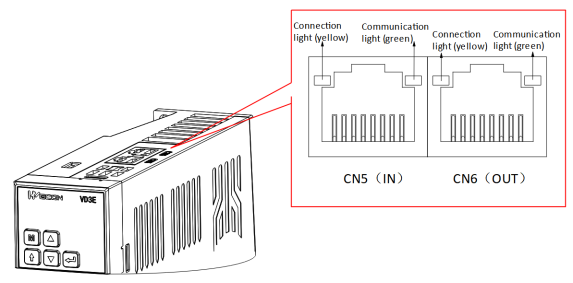
Figure 6-4 Communication indicator position
(1) Connection lamp (yellow)
Used to display the status of CN5 and CN6 communication interfaces, and the display contents are shown in the following table.
| Connection lamp status | Explanation |
|---|---|
| OFF | The port is not connected to the network cable |
| ON | The port is connected to the network cable |
(2) Communication lamp (green)
Used to display the status of CN5 and CN6 communication connections, as shown in the following table.
| Connection lamp status | Explanation |
|---|---|
| ON | No communication connection was established with the master station |
| BLINKING | A communication connection has been established with the master station |
Process Data PDO
PDO outputs process data in real time. PDO can be divided into RPDO (for receiving instructions from master station) and TPDO (for feeding back its own status from slave station).
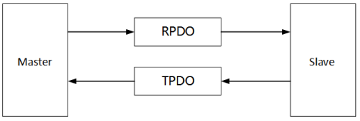
Figure 6-6 PDO schematic diagram
(1) PDO mapping parameters
PDO mapping is used to establish the mapping relationship between object dictionary and PDO. 1600h-17FFh is RPDO, 1A00h-1BFFh is TPDO:
| Name | Parameter | Nature |
|---|---|---|
| RPDO | 1600h | Variable mapping |
| 1701h ~ 1705h | Fixed mapping | |
| TPDO | 1A00h | Variable mapping |
| 1B01h ~ 1B04h | Fixed mapping |
The following figure is an example of RxPDO mapping.
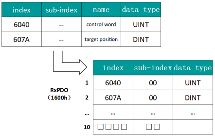
Figure 6-7 Examples of RxPDO mapping
The data type is defined as follows:
| Data type | Description | Numerical range |
|---|---|---|
| SINT | Signed 8bit | -128 ~ 127 |
| USINT | Unsigned 8bit | 0 ~ 255 |
| INT | Signed 16bit | -32768 ~ 32767 |
| UINT | Unsigned 16bit | 0~65535 |
| DINT | Signed 32bit | -21247483648 ~ 21247483647 |
| UDINT | Unsigned 32bit | 0 ~ 4294967295 |
| STRING | String Value | ASCII |
The following figure is an example of TxPDO mapping.
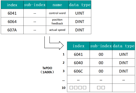
Figure 6-8 Examples of TxPDO mapping
The following figure is an example of a SyncManager PDO mapping.
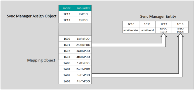
Figure 6-8 SyncManager PDO Mapping Example
(2) Synchronize management of PDO allocation settings
In EtherCAT periodic data communication, process data can contain multiple PDO mapping data objects. The data objects 0x1C10 ~ Ox1C2F used in CoE protocol define the corresponding PDO mapping object list of SM (Synchronous Management Channel), and multiple PDO can be mapped in different sub-indexes.
| Index (hex) | Sub-index (hex) | Content |
|---|---|---|
| 1C12 | 01 | Choose to use one of 0x1600, 0x1701-0x1705 as the actual RPDO |
| 1C13 | 01 | Select to use one of 0x1A00, 0x1B01-0x1B04 as the actual TPDO |
(3) PDO configuration
The PDO mapping parameter contains a pointer to the PDO corresponding process data that the PDO needs to send or receive, including index, sub-index and mapping object length. The sub-index 0 records the number N of objects mapped by the PDO, and the length of each PDO data can reach 4N bytes at most, which can map one or more objects at the same time. Sub-index ~ N is the mapping content. The mapping parameter content is defined as follows:
| Number of digits | 31 | ... | 16 | 15 | ... | 8 | 7 | ... | 0 |
|---|---|---|---|---|---|---|---|---|---|
| Description | Index | Sub-index | Object length | ||||||
The index and sub-index together determine the position of the object in the object dictionary, and the object length indicates the specific bit length of the object (hexadecimal representation)
| Object length | bit length |
| 08h | 8 |
| 10h | 16 |
| 20h | 32 |
For example, the mapping parameter of 6040h-00 (control word) is 60400010h
|
The PDO configuration can only be designed when the EtherCAT communication state machine is in pre-operation (Pro-Operation, panel display 2), otherwise an error will be reported. The PDO configuration parameters cannot be stored in the EEPROM. Therefore, after each power-on, please reconfigure the mapping object, otherwise, the mapping object is the default parameter of the drive The SDO fault codes are returned when: Modify PDO parameters in non-pre-operation state; Pre-write values other than 1600/1701 ~ 1705 in 1C12; Values other than 1A00/1B01 ~ 1B04 are pre-written in 1C13. No more than 10 variable mappings can be added, otherwise the servo activation failure may occur. |

Email Data SDO
EtherCAT Email data SDO is used to transmit aperiodic data, such as configuration of communication parameters, servo drive operation parameters and so on. EtherCAT's CoE service types include:
(1) Emergency information; ② SDO request; ③ SDO response; ④ TxPDO; ⑤ RxPDO; ⑥ Remote TxPDO sending request; ⑦ Remote RxPDO sending request; ⑦ SDO information.
Wecon VD3E series bus servo drives currently support ② SDO requests; ③ SDO response.
Distributed Clock
Distributed clock enables all EtherCAT devices to use the same system time, thus controlling the synchronous execution of tasks of each device. The slave station device can generate a synchronization signal according to the synchronized system time. Wecon VD3E series bus servo drives only support DC synchronous mode.
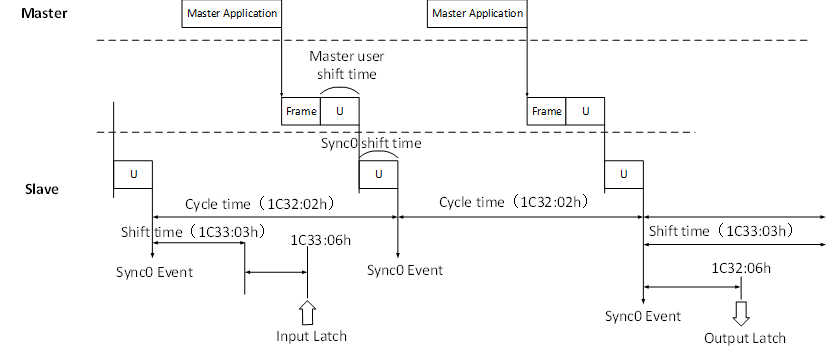
Figure 6-9 DC Synchronous Mode Schematic Diagram
Status Indication
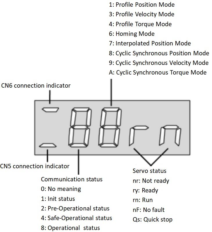
Figure 6-10 Status indication schema
Description:
(1) Communication connection status
The first digit tube from the left of the 5-bit LED indicator on the servo drive panel is used to display the connection status of the two Ethernet communication ports: upper "-" CN6 (OUT) and lower "-" CN5 (IN)
Long dark: No communication connection detected
Long Bright: A communication connection has been established
(2) Communication Operating status
The servo drive panel of the 5-bit LED indicator lamp is the second digit tube from the left, which is used to display the EtherCAT state machine status of the slave station in character form.
| Panel display | Meaning |
| Initialization state |
| Pre-operation status |
| Safe operation status |
| Operating status |


(3) Display of servo operation mode
Servo drive panel 5-bit LED indicator from the left of the third digit tube, used to display hexadecimal digital form display servo drive current operation mode.
| Panel display | Meaning |
| Contour position control mode |
| Contour speed control mode |
| Contour torque control mode |
| Origin return mode |
| Interpolation mode |
| Cyclic Synchronous Position mode |
| Periodic synchronous speed mode |
| Periodic synchronous torque mode |


(4)Servo status display
Servo drive panel 5-bit LED indicator from the left of the fourth and fifth digit tube, used to display the servo status of the slave station.
| Panel display | Meaning |
| Not ready nr |
| Get ready ry |
| Run rn |
| Failure-free nF |


Introduction to CiA402 Control
The use of Wecon VD3E Series Bus Type servo drives must be guided according to the procedure specified in Standard 402 Protocol.
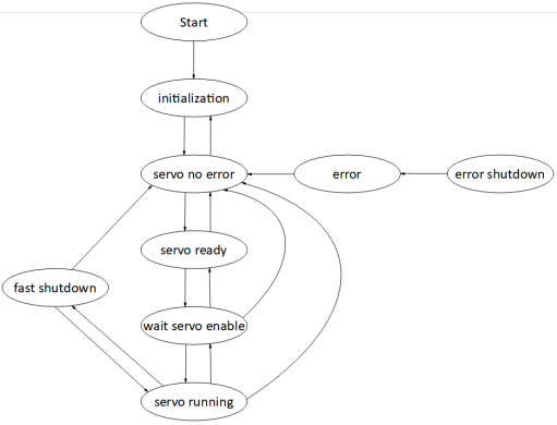
Figure 6-11 CiA402 state machine switching schema
| Status | Description |
|---|---|
| Initialization | Drive initialization, internal self-test has completed. Parameters cannot be set, and servo drive function cannot be performed. |
| Servo trouble-free | There is no fault in the servo drive. Parameters can be set. |
| Servo ready | Servo drives are ready. Parameters can be set. |
| Wait to turn on servo enable | The servo drive waits to turn on the servo enable. Parameters can be set. |
| Servo operation | The servo drive is running normally. |
| Quick stop | The servo drive is performing the quick shutdown function. Only function codes with the attribute "Run valid" can be set. |
| Malfunction shutdown | The servo drive is performing the fault shutdown function. Only function codes with the attribute "Run valid" can be set. |
| Fault | Failure shutdown is complete, and all drive functions are disabled. Allow parameters to be changed to troubleshoot. |
Basic Characteristics
The EtherCAT network cable is connected to the CN5 (IN), CN6 (OUT) interfaces, and its electrical characteristics conform to IEEE 802.3 standard.

Figure 6-12 Communication port
| Pin | Name | Function description |
|---|---|---|
| 1 | TX+ | Sending data+ |
| 2 | TX- | Sending data- |
| 3 | RX+ | Receiving data+ |
| 4 | - | - |
| 5 | - | - |
| 6 | RX- | Receiving data- |
| 7 | - | - |
| 8 | - | - |
EtherCAT communication topology connections are very flexible, taking linear connections and ring connections as examples:
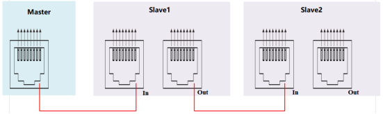
Figure 6-13 Linear connection
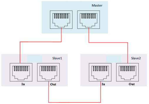
Figure 6-114 Ring connection