
Spraying machine PID control case
1.Requirements of project
The customer plans to use two VZ2400 3.7kW inverters to control one spraying machine. It is required that the frequency of the main motor is adjustable and the auxiliary motor is controlled by following system. Customers have used one potentiometer before, and the effect is not good.
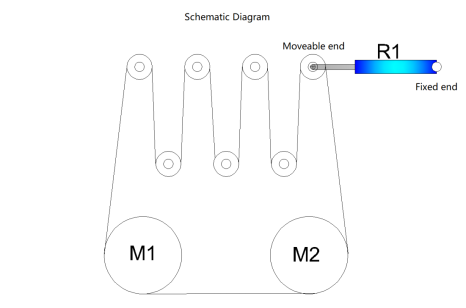
The schematic diagram is as follows:
M1: Main motor M2: Auxiliary motor R1: Sliding resistance thin Line: belt
The two motors are asynchronous motors, but the synchronous inverter with asynchronous motor is easy to damage the motor. It is recommended to choose a general frequency converter, but it is not adopted. Therefore, according to the customer's description, the control scheme was changed, and the auxiliary motor control was changed to PID control. The wiring diagram is as follows:
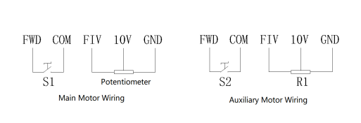
During debugging, considering the stability of PID adjustment, the acceleration and deceleration time of the main motor is adjusted to 100s, so as to make the auxiliary motor controlled stably. The use is relatively smooth when the machine is started, but when the machine is shut down, the belt is stuck because the two motors are not shut down at the same time. And set all shutdowns to free stop.
2.Parameter settings
Main motor:
| Parameter | Description | Set Value |
P0.01 | vector mode | 1 |
P0.02 | External start | 1 |
| P0.03 | Frequency source superposition selection | 2 |
| P0.17 | Carrie frequency | 100 |
| P0.18 | Carrier frequency adjustment with temperature | 100 |
| P6.10 | FOV offset coeffcient |
Auxiliary motor parameters:
| Parameter | Description | Set Value |
P0.01 | vector mode | 2 |
P0.02 | External start | 1 |
| P0.08 | Acceleration time 1 | 8 |
| P6.10 | MO1 function | 1 |
| PA.00 | PID setting source | 0 |
| PA.01 | PID digita setting | 50 |
| PA.02 | PID feedback source | 0 |
| PA.03 | PID action direction | 1 |