Xinje
XC serial
Support Series: Xinjie XC Series
V-Box Settings
| Item | Settings | Note |
| Protocol | XINJE XC MODBUS | |
| Connection | RS232 | |
| Baud rate | 19200 | |
| Data bit | 8 | |
| Parity | EVEN | |
| Stop bit | 1 | |
| PLC station No. | 1 |

Address List
| Type | Device registers | HMI registers | Format | Range | Note |
| Bit | M | M | M d | 0~8511 | |
| Bit | X | X | X o | 0~1747 | |
| Bit | Y | Y | Y o | 0~1747 | |
| Bit | S | S | S d | 0~1023 | |
| Bit | T | T | T d | 0~4095 | |
| Bit | C | C | C d | 0~634 | |
| Word | D | D | D d | 0~8511 | |
| Word | TD | TD | TD d | 0~618 | |
| Word | CD | CD | CD d | 0~634 | |
| Word | FD | FD | FD d | 0~8511 |
PLC Settings
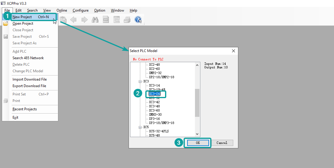
Create the new project, and select the specific model according to the actual PLC
Program the PLC

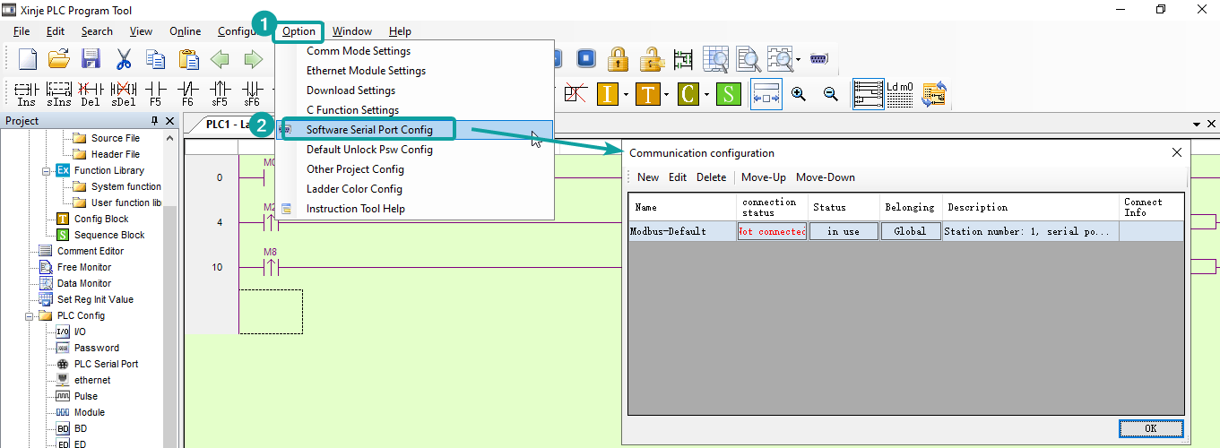
Connect PLC with PC through RS232-USB converter cable. Click [Option]-[Software Serial Port Config] to open the software connection setup window, and select the serial port, if the red text prompt "Connect To PLC Succeeded", which means the connection is setup successfully, then click OK to save the settings.

Change the PLC communication setup if required. Double click the tree node [PLC Serial Port] from Project tree. And change Modbus parameters, then click [Write to PLC] and OK to finish.

Click [Online]-[Download Program] to download program into PLC. And the download pop up window would pop up, then click OK.

Cable Wiring
Figure


Pin Definition Diagram

XD serial
V-Box Settings
Supported Series: Xinjie XD/XE Series PLC
| Item | Settings | Note |
| Protocol | XINJE XD/XC MODBUS | |
| Connection | RS232 | |
| Baud rate | 19200 | |
| Data bit | 8 | |
| Parity | EVEN | |
| Stop bit | 1 | |
| PLC station No. | 1 |

Address List
| Type | Device registers | HMI registers | Format | Range | Note |
| Bit | M | M | M d | 0~74999 | |
| Bit | X1xx | X1xx | X1xx o | 0~1177 | |
| Bit | X2xx | X2xx | X2xx o | 0~277 | |
| Bit | X | X | X o | 0~77 | |
| Bit | Y1xx | Y1xx | Y1xx o | 0~1177 | |
| Bit | Y2xx | Y2xx | Y2xx o | 0~277 | |
| Bit | Y | Y | Y o | 0~4095 | |
| Bit | SM | SM | SM d | 0~4999 | |
| Bit | T | T | T d | 0~4999 | |
| Bit | C | C | C d | 0~4999 | |
| Bit | ET | ET | ET d | 0~31 | |
| Bit | SE | SE | SE d | 0~31 | |
| Bit | HM | HM | HM d | 0~11999 | |
| Bit | HSC | HSC | HSC d | 0~39 | |
| Bit | HS | HS | HS d | 0~999 | |
| Bit | HT | HT | HT d | 0~1999 | |
| Bit | HC | HC | HC d | 0~1999 | |
| Bit | S | S | S d | 0~7999 | |
| Word | D | D | D d | 0~69999 | |
| Word | ID | ID | ID d | 0~99 | |
| Word | ID1xx | ID1xx | ID1xx d | 0~999 | |
| Word | ID2xx | ID2xx | ID2xx d | 0~299 | |
| Word | QD | QD | QD d | 0~99 | |
| Word | QD1xx | QD1xx | QD1xx d | 0~999 | |
| Word | QD2xx | QD2xx | QD2xx d | 0~299 | |
| Word | SD | SD | SD d | 0~4999 | |
| Word | TD | TD | TD d | 0~575 | |
| Word | CD | CD | CD d | 0~575 | |
| Word | ETD | ETD | ETD d | 0~31 | |
| Word | HD | HD | HD d | 0~24999 | |
| Word | HSD | HSD | HSD d | 0~1023 | |
| Word | HTD | HTD | HTD d | 0~95 | |
| Word | HCD | HCD | HCD d | 0~95 | |
| Word | HSCD | HSCD | HSCD d | 0~31 | |
| Word | FD | FD | FD d | 0~8191 | |
| Word | SFD | SFD | SFD d | 0~5999 | |
| Word | FS | FS | FS d | 0~47 |
PLC Settings
Create the new project, and select the specific model according to the actual PLC

Program the PLC

Connect PLC with PC through RS232-USB converter cable. Click [Option]-[Software Serial Port Config]-[Communication configuration] to open the PC connection configuration.
New a Modbus configuration, and Click [Comm-Test] to test connection, if shows "Connect To PLC Succeeded", which means PLC connection set up successfully. And click OK to save the settings.

Remember to click the Status cell of new created Modbus configuration for change the status into "in use", then click OK to exit.

After done the previous steps, it would prompt like the below.

Click [Online]-[Download Program & Data], and wait for a while, the pop up window would ask for whether to stop PLC, and click [Stop PLC, contitue download]

And then the XDPro ask for which options want to rewrite, and click OK to finish.

If download successfully, it would prompt like the below.

Cable Wiring
Figure

Pin Definition Diagram
