1 Communication
WECON
LX3V Serial
Supported series: Wecon LX2V/ LX2E/ LX3V/LX3VP/LX3VE/LX3VM
1)V-BOX setting
| Item | Settings | Note |
| Protocol | WECON LX2V/ LX2E/ LX3V/LX3VP/LX3VE/LX3VM | |
| Connection | RS422/RS485 | |
| Baud rate | 9600 | |
| Data bit | 7 | |
| Parity | EVEN | |
| Stop bit | 1 | |
| PLC station No. | 1 |
2)Address List
| Type | Device registers | HMI registers | Format | Range | Note |
| Bit | X | X | Xo | 0~303237 | |
| Y | Y | Y o | 0~303237 | ||
| M | M | M d | 0~99999 | ||
| T | T | T d | 0~99999 | ||
| C | C | C d | 0~99999 | ||
| S | S | S d | 0~99999 | ||
| Word | X | X | Xo | 0~303237 | |
| Y | Y | Y o | 0~303237 | ||
| M | M | M d | 0~99999 | ||
| T | T | T d | 0~99999 | ||
| C | C | C d | 0~199 | ||
| D | D | D d | 0~7999 | ||
| S | S | S d | 0~99999 | ||
| SD | SD | SD d | 8000~9999 |
3)Configure the communication protocol

4)Cable Wiring
- RS422

- RS485

LX5V Serial
This example introduces the establishment of serial port communication between V-BOX and LX5V. It is introduced through three parts: PLC software configuration, V-BOX software configuration, and hardware wiring.
Software configuration of PLC
1)PLC programming software

2)New PLC project
Click New Project and select the PLC model.

3)Set Serial port parameters
Follow the steps below to configure Serial port parameters
Baud rate:115200
Data bit:8
Stop bit:1
Parity:No verification

4)Registers list

V-BOX software configuration
1)V-BOX programming software

2)V-NET add device
Open V-NET client software → add device. As shown in the figure below, click "+" in the order of steps, and the Add Device window will pop up, enter the access key, password and remark, to add the device.

3)Set communication port parameters
Click the communication configuration button on the left to find the communication protocol with LX5V. After selecting the protocol, configure the communication parameters of the COM port.
Baud rate:115200
Data bit:8
Stop bit:1
Parity:No verification

hardware connection
1)Hardware wiring diagram


The above are all the steps for establishing serial port communication between V-BOX with LX5V PLC.
LX5V-N Ethernet
This example introduces the establishment of Ethernet communication between V-BOX and LX5V-N. It is introduced through three parts: PLC software configuration, V-BOX software configuration, and hardware wiring.
Software configuration of PLC
1)PLC programming software
2)New PLC project
Click New Project and select the PLC model.

3)Set Ethernet port parameters
Follow the steps below to configure Ethernet parameters
PLC IP address:192.168.39.200
default gateway:192.168.39.1
subnet mask:255.255.255.0

4)Registers list
V-BOX software configuration
1)V-BOX programming software
2)V-NET add device
Open V-NET client software → add device. As shown in the figure below, click "+" in the order of steps, and the Add Device window will pop up, enter the access key, password and remark, to add the device.
3)Set communication Protocol
Click Communication to configure the LX5V plc protocol and IP address.

hardware connection
1)Hardware wiring diagram

The above are all the steps for establishing ethernet communication between V-BOX with LX5V PLC.
Allen-Bradley(Rockwell)
DF1 Advanced Serial
MicroLogix 1000/1100/1200/1400/1500; SLC 5/03 5/04 5/05; PLC-5
1) V-Box Settings
| Item | Recommended | Note |
|---|---|---|
| Protocol | Allen Bradley DF1 Advanced | |
| Connection | RS232 | |
| Baud rate | 19200 | |
| Stop bits | 1 | |
| Data bits | 8 | |
| Parity | None | |
| PLC Station No. | 1 | |
| HMI Station No. | 0 |
2) Address List
| Type | Device registers | Format | Range | Note |
|---|---|---|---|---|
| Bit | I1 | I1ddd.dd | 0.0~255.15 | Only able to communicate with file number I1 |
| O0 | O0ddd.dd | 0.0~255.15 | Only able to communicate with file number O0 | |
| S2 | S2ddd.dd | 0.0~255.15 | Only able to communicate with file number S2 | |
| B3 | B3ddd.dd | 0.0~255.15 | Only able to communicate with file number B3 | |
| BN | BNddddd.dd | 0.0~99255.15 | Bit data file B0~B99 First two digits is for file number For example, BN13001.00 represents file number B13, address 001, the 0th bit. | |
| N7 | N7ddd.dd | 0.0~255.15 | Only able to communicate with file number N7 | |
| NN | NNddddd.dd | 0.0~99255.15 | Integer data file bit format N0~N99 First two digits is for file number For example, NN13001.00 represents file number N13, address 001, the 0th bit. | |
| Word | S2 | S2ddd | 0~255 | Only able to communicate with file number S2 |
| T4S | T4Sddd | 0~255 | Only able to communicate with file number T4 (Timer Preset Value) | |
| T4P | T4Pddd | 0~255 | Only able to communicate with file number T4 (Timer Accumulator Value) | |
| TNS | TNSddddd | 0~99255 | Timer Preset Value First two digits is for file number For example, TNS99255 represents file number T99, address 255. | |
| TNP | TNPddddd | 0~99255 | Timer Accumulator Value First two digits is for file number For example, TNP99255 represents file number T99, address 255. | |
| C5S | C5Sddd | 0~255 | Only able to communicate with file number C5 (Counter Preset Value) | |
| C5P | C5Pddd | 0~255 | Only able to communicate with file number C5 (Counter Accumulator Value) | |
| CNS | CNSddddd | 0~99255 | Counter Preset Value First two digits is for file number For example, CNS99255 represents file number C99, address 255. | |
| CNP | CNPddddd | 0~99255 | Counter Accumulator Value First two digits is for file number For example, CNP99255 represents file number C99, address 255. | |
| N7 | N7ddd | 0~255 | Only able to communicate with file number N7 | |
| NN | NNddd | 0~99255 | Integer data file First two digits is for file number For example, NN99255 represents file number N99, address 255. | |
| Double Word | F8 | F8ddd | 0~255 | Only able to communicate with file number N7 |
| FN | FNddddd | 0~99255 | Floating point data file First two digits is for file number For example, FN99255 represents file number F99, address 255. | |
| LN | LNddddd | 0~99255 | Long |
3) Cable Wiring

MicroLogix Serial
MicroLogix 1000/1100/1200/1400/1500; SLC 5/03 5/04 5/05 PLC-5
1)V-BOX setting
| Item | Settings | Note |
| Protocol | Allen-Bradley DF1 Advanced | |
| Connection | RS232 | |
| Baud rate | 19200 | |
| Data bit | 8 | |
| Parity | None | |
| Stop bit | 1 | |
| PLC station No. | 1 |
2)Address List
| Type | Device registers | Format | Range | Note |
| Bit | I | I d.d | 0.0~255.15 | |
| O | O d.d | 0.0~255.15 | ||
| B | B nnhh.dd | 0.0~ffff.15 | nn: block number (hex) | |
| S | S d.d | 0.0~255.15 | ||
| N | N nnhh.dd | 0.0~ffff.15 | nn: block number (hex) | |
| Word | S | S d | 0~255 | |
| TS | TS nnhh | 0~ffff | nn: block number (hex) | |
| TP | TP nnhh | 0~ffff | ||
| CS | CS nnhh | 0~ffff | ||
| CP | CP nnhh | 0~ffff | ||
| N | N nnhh | 0~ffff | ||
| C | C nnhh | 0~ffff | ||
| T | T nnhh | 0~ffff | ||
| R | R nnhh | 0~ffff |
3)Configure the communication protocol
4)Configure the communication protocol

Micro850_FreeTag Ethernet
This example introduces the establishment of Ethernet communication between Wecon V-box and CompactLogix L1769. It is introduced through three parts: PLC software configuration, V-box software configuration, and hardware wiring.
Software configuration of PLC
1)PLC programming software

2)New PLC project
Click New Project and select the PLC model.


3)Set Ethernet parameters
Follow the steps below to configure Ethernet parameters
PLC IP address:192.168.40.101
default gateway:192.168.40.1
subnet mask:255.255.255.0

V-box software configuration
1)V-box programming software

2)Configure device network
Click the Configuration Download button![]() , It is used to configure the device network, update the device time, obtain the device machine code, check the device network, etc.
, It is used to configure the device network, update the device time, obtain the device machine code, check the device network, etc.
In the example below, the IP address of V-Box is configured as 192.168.40.66, and the networking method is 4G connection

3)V-net add device
Open VNET client software → add device. As shown in the figure below, click "+" in the order of steps, and the Add Device window will pop up, enter the device machine code/product code, device password, and device alias to add the device. 
4)Set communication port parameters
In the device list on the left, find the Vbox that communicates with the L1769, click it and select configuration,communication port configuration in the main interface to add a communication protocol.

The communication port is selected as Ethernet, the device type is selected as Allen-Bradley, the protocol is Allen-BradleyMicro850_FreeTag EthemetIP, and the IP is the internal IP address of the L1769 PLC. The port number is 44818.

After adding the protocol Allen-BradleyMicro850_FreeTag, click icon add label.
5)Engineering production
According to your own needs, use the V-NET client software to edit the required data monitoring points.

hardware connection
1)Hardware wiring diagram
This example introduces Wecon V-box with Allen-Bradley L1769 PLC to establish communication through Ethernet. The connection diagram is as follows:

The above are all the steps for establishing Ethernet communication between Wecon V-box with CompactLogix L1769 PLC.
Micro850_FreeTag Ethernet(new)
This example introduces the establishment of Ethernet communication between Wecon V-box and 2080-LC50-48QWB,Micro850. It is introduced through three parts: PLC software configuration, V-box software configuration.
Software configuration of PLC
1)PLC programming software:Connected Components Workbench™

2)New PLC project
Click New Project and select the PLC model.

3)Set Ethernet parameters
Follow the steps below to configure Ethernet parameters
PLC IP address:192.168.39.56
default gateway:192.168.39.1
subnet mask:255.255.255.0

4)connect PLC
When downloading the setting, need to change the status of the PLC to PRG

V-box software configuration
1)V-box programming software

2)Set communication port parameters
In the device list on the left, find the Vbox that communicates with the L1769, click it and select configuration,communication port configuration in the main interface to add a communication protocol.

The communication port is selected as Ethernet, the device type is selected as Allen-Bradley, the protocol is Allen-BradleyMicro850_FreeTag EthemetIP, and the IP is the internal IP address of the L1769 PLC. The port number is 44818.

Export variables from PLC, select CSV file, comma delimited.


After adding the protocol Allen-BradleyMicro850_FreeTag, click icon add label.

3)Engineering production
According to your own needs, use the V-NET client software to edit the required data monitoring points.

Ethernet DF1
Crouzet PLC
CROUZET M3 (FBD) Serial
Support Series: Crouzet Millenium 3 CD12/CB12
1)V-BOX setting
| Item | Recommended | Note |
|---|---|---|
| Protocol | CROUZET M3 (FBD) | |
| Connection | RS232 | |
| Baud rate | 115200 | |
| Stop bits | 1 | |
| Data bits | 7 | |
| Parity | EVEN |
2)Address List
| Type | Device registers | Format | Range | Note |
|---|---|---|---|---|
| Bit | I | I DD | 1~99 | Input |
| SLIBit | SLIBit DD.dd | 1.0~24.15 | Serial Link Input | |
| SLOBit | SLOBit DD.dd | 25.0~48.15 | Serial Link Output(Read only) | |
| State | State D | 1~1 | PLC state(Read only) | |
| Word | AI | AI DD | 1~99 | Analog Input |
| SLIn | SLIn DD | 1~24 | Serial Link Input | |
| SLOut | SLOut DD | 25~48 | Serial Link Output(Read only) | |
| Time | Time D | 1~6 | Time1: Second Time2: Minute Time3: Hour Time4: Day Time5: Month Time6: Year | |
| Order | Order D | 1~1 | Running command(Write only) =2: Run mode; =1: Stop mode; |
3)Cable Wiring

EMERSON
RTU Slave
Supported series: EC10 series
1)V-BOX setting
| Items | Settings | Note |
| Protocol | Emerson 984 RTU Slave MODBUS | |
| Connection | RS485 | |
| Baud rate | 19200 | |
| Data bit | 8 | |
| Parity | EVEN | |
| Stop bit | 1 | |
| Device station No. | 1 | Need to be same as the PLC setting |
2)PLC Setting
Remember to use the Control Star to enable the Modbus RTU communication for port 1 in system block before dowload into PLC.


3)Address List
| Type | Device registers | Format | Range | Note |
| Bit | Y | YOOO | 0~377 | |
| X | XOOO | 0~377 | ||
| M0 | M0DDDD | 0~2047 | ||
| M1 | M1DDDDD | 2048~10239 | ||
| SM0 | SM0DDD | 0~255 | ||
| SM1 | SM1DDD | 256~511 | ||
| S0 | S0DDDD | 0~1023 | ||
| S1 | S1DDDD | 1024~4095 | ||
| T0 | T0DDD | 0~255 | ||
| T1 | T1DDD | 256~511 | ||
| C0 | C0DDD | 0~255 | ||
| C1 | C1DDD | 256~306 | ||
| Word | D | DDDDD | 0~7999 | |
| Z | ZDD | 0~15 | ||
| TW0 | TW0DDD | 0~255 | ||
| TW1 | TW1DDD | 256~511 | ||
| SD0 | SD0DDD | 0~255 | ||
| SD1 | SD1DDD | 256~511 | ||
| CW | CWDDD | 0~306 | ||
| Double Word | CW0 | CW0DDD | 200~255 | |
| CW1 | CW1DDDDD | 256~99999 |
4) Cable Wiring

HollySys PLC
LK Modbus RTU
Supported Series: HollySys LK series PLC
1)V-BOX setting
| Items | Settings | Note |
| Protocol | HollySys LK Modbus RTU | |
| Connection | RS485 | |
| Baud rate | 38400 | |
| Data bit | 8 | |
| Parity | None | |
| Stop bit | 1 | |
| Device station No. | 1 |
2)Address List
| Type | Device registers | Format | Range | Note |
|---|---|---|---|---|
| Bit | QX | QXDDDDD.dd | 0~65535.15 | |
| Bit | IX | IXDDDDD.dd | 0~65535.15 | |
| Bit | MX | MXDDDDD.dd | 0~65535.15 | |
| Word | QW | QWDDDDD | 0~99999 | |
| Word | IW | IWDDDDD | 0~99999 | |
| Word | MW | MWDDDDD | 0~99999 | |
| Word | MD | MDDDDDD | 0~99999 |
3)Cable Wiring

LM Modbus RTU
Supported Series: HollySys LM3109/LM3107 PLC
1)V-BOX setting
| Items | Settings | Optional | Note |
| Protocol | HollySys LM Modbus RTU | HollySys LM Modbus RTU | |
| Connection | RS232 | RS485 | |
| Baud rate | 38400 | 38400 | |
| Data bit | 8 | 8 | |
| Parity | None | None | |
| Stop bit | 1 | 1 | |
| Device station No. | 1 | 1 |
2)Address List
| Type | Device registers | Format | Range | Note |
|---|---|---|---|---|
| Bit | QX | QXDDDDD.o | 0~99999.7 | |
| Bit | IX | IXDDDDD.o | 0~99999.7 | |
| Bit | MX | MXDDDDD.o | 0~99999.7 | |
| Word | QW | QWDDDDD | 0~99999 | |
| Word | IW | IWDDDDD | 0~99999 | |
| Word | MW | MWDDDDD | 0~99999 | |
| Word | MD | MDDDDDD | 0~99999 |
Cable Wiring
RS232

RS485

Siemens
S7-200 Smart Ethernet
S7-300 Ethernet
Supported Series: Siemens S7-300 series PLC
1)V-BOX setting
| Items | Settings | Note |
| Protocol | Simens S7-300 Ethernet | |
| Connection | Ethernet | |
| Port No. | 102 | |
| PLC station No. | 2 | Need to be same as the PLC setting |
2)Address List
| Type | Device register | HMI register | Format | Range | Note |
| Bit | I | I | I ddddd.o | 0.0~99999.7 | |
| Q | Q | Q ddddd.o | 0.0~99999.7 | ||
| M | M | M ddddd.o | 0.0~99999.7 | ||
| DB0.DB~DB99.DB | DBxDBD | DBxDB nndddd.o | 0.0~99999999.7 | nn: block number; dddd: address; | |
| Word | I | IW | IW ddddd | 0~99999 | |
| Q | QW | QW ddddd | 0~99999 | ||
| M | MB | MB ddddd | 0~99999 | ||
| MW | MW ddddd | 0~99999 | MW0=MB(0~1) MW2=MB(2~3) Address value is a multiple of 2 | ||
| MD | MD ddddd | 0~99999 | MD0=MB(0~3) MD4=MB(4~7) Address value is a multiple of 4 | ||
| DB0.DB~DB99.DB | DBxDBB | DBxDBB nndddd | 0~99999999 | nn: block number; dddd: address | |
| DBxDBW | DBxDBW nndddd | 0~99999999 | |||
| DBxDBD | DBxDBD nndddd | 0~99999999 |
3)Configure the communication protocol

4)Cable Wiring

S7-1200 Ethernet
S7-XXX Ethernet l
Supported Series: Siemens S7-400, S7-1200 and S7-1500
1)V-BOX setting
| Items | Settings | Note |
|---|---|---|
| Protocol | Siemens S7-XXX | |
| Connection | Ethernet | |
| Port No. | 102 | |
| Device No. | Slot (Default 1 for S7-1500/ 2 for S7-1200/ 3 for S7-400) | |
| HMI No. | Rack (Default as 0) |
Slot from TIA Portal is equal to Device No. of V-net
Rack from TIA Portal is equal to HMI No. of V-net


2)Address List
| Type | Device register | HMI register | Format | Range | Note |
| Bit | I | I | M d.o | d:0--9999 o:0-7 | |
| Q | Q | Q d.o | d:0--9999 o:0-7 | ||
| M | M | M d.o | d:0--9999 o:0-7 | ||
| DB0.DB-DB99.DB | DBxDB | DBxDBnndddd.o | nn:0-9999, dddd:0-9999, o:0-7 | nn:DB No. dddd:address value o: digit address | |
| Word | M | MB | MB d | d:0-99999 | |
| M | MW | MW d | d:0-99999 | MW0=MB(0~1) MW2=MB(2~3) Address value is a multiple of 2 | |
| M | MD | MD d | d:0-99999 | MD0=MB(0~3) MD4=MB(4~7) Address value is a multiple of 4 | |
| I | IW | IW d | d:0-99999 | ||
| Q | QW | QW d | d:0-99999 | ||
| DB0.DB-DB99.DB | DBxDBB | DBxDBBnndddd | nn:0-9999 dddd:0-9999 | nn:DB No. dddd:address value | |
| DB0.DB-DB99.DB | DBxDBW | DBxDBWnndddd | nn:0-9999 dddd:0-9999 | nn:DB No. dddd:address value Address value is a multiple of 2 | |
| DB0.DB-DB99.DB | DBxDBD | DBxDBDnndddd | nn:0-9999 dddd:0-9999 | nn:DB No. dddd:address value Address value is a multiple of 4 |
3)Configure the communication protocol

✎Note:
- The S7-1200 supports simultaneous connection of three devices, so the driver supports simultaneous access to PLC by three V-BOX.
- V-BOX access PLC, use S7 protocol, access PLC TSAP 02.01 (s7-1200 PROFINET interface only supports three connections, the default support), detailed reference to the system manual of S7-1200.
4)Cable Wiring

LOGO Ethernet
Supported Series: Siemens Logo 0BA0, 0BA1 series
V-BOX Settings
| Items | Settings | Note |
| Protocol | Siemens LOGO | |
| Connection | Ethernet | |
| Port No. | 102 | |
| PLC station No. | 2 |
Address List
| Number | Address Type | Data Type | Range | DB Address | PLC Address |
| 1 | RTC | Word | 1-7 | DB1.DBX984.0 | 0x001ec0 |
| 2 | VB | Byte | 0-1469 | DB1.DBX0.0 | 0x000000 |
| 3 | VD | Double Word | 0-1466 | DB1.DBX0.0 | 0x000000 |
| 4 | VW | Word | 0-1468 | DB1.DBX0.0 | 0x000000 |
| 5 | NAQ | Word | 1-32 | DB1.DBX1406.0 | 0x002bf0 |
| 6 | NAI | Word | 1-64 | DB1.DBX1262.0 | 0x002770 |
| 7 | AM | Word | 1-64 | DB1.DBX1118.0 | 0x0022f0 |
| 8 | AQ | Word | 1-16 | DB1.DBX1072.0 | 0x002180 |
| 9 | AI | Word | 1-16 | DB1.DBX1032.0 | 0x002040 |
| 10 | I | Bit | 1-64 | DB1.DBX1024.0 | 0x002000 |
| 11 | Q | Bit | 1-64 | DB1.DBX1064.0 | 0x002140 |
| 12 | M | Bit | 1-112 | DB1.DBX1104.0 | 0x002280 |
| 13 | NI | Bit | 1-128 | DB1.DBX1246.0 | 0x0026f0 |
| 14 | NQ | Bit | 1-128 | DB1.DBX1390.0 | 0x002b70 |
| 15 | V | Bit | 0-14697 | DB1.DBX0.0 | 0x000000 |
PLC Settings in LOGO Software:
Click [Tools]--[Ethernet Connections],shown as below.

Set Ethernet connection parameter. IP, Subnet Mask, shown as below.

TSAP set:The value set by local TSAP is the remote TSAP set in HMI. PLC's remote TSAP is the opposite,shown as below.

Download Project: Click "Address book" to add the IP address to be downloaded (fi."Detect" to check whether the IP address can be detected. Then click “ok”, and the system will prompt that PLC will be "STOP" mode. Click “YES” to start download.

V-BOX Communication Settings
Set PLC IP in [IP Address] settings;

Enable V-BOX Ethernet in [Network];

TSAP setting
- The initialization script needs to set the source TSAP address and the target TSAP address, otherwise the communication will not be successful.
addr_setword("@W_0#HSW1200",8192) -- Set the source TSAP address
addr_setword("@W_0#HSW1201",4096) -- Set the destination TSAP address
end
Note: The name of the test script is init, 8192 and 4096 are the data used for the test, there is no HSW address in the register option, but you can directly set the value of the corresponding address through the code.
✎Note:
- Communication port configuration:
- Continuous length needs to be set to 0.
- Integration interval needs to be set to 1. (no change may result in data errors)
- Set Port and Device Station NO.
- Other set as defaulted.
- Notes on the use of registers:
- Register VD: Use only registers that are multiples of 4, such as 0, 4, 8, etc.
- Register VW: Use only registers thay are multiples of 2, such as 0, 2, 4 etc. (Using an odd-length register may result in data errors, such as 2 3 4 )
Mitsubishi
FX1S,1N,2N Serial
Supported Series: Mitsubishi FX1S, FX1N, FX2N series
1)V-BOX Settings
| Item | Settings | Note |
| Protocol | Mitsubishi FX1S/FX1N/FX2N | |
| Connection | RS422/RS485/RS232 | |
| Baud rate | 9600~115200 | |
| Data bit | 7/8 | |
| Parity | EVEN/Odd/None | |
| Stop bit | 1/2 | |
| PLC station No. | 1~255 |
2)Address List
| Type | Device registers | HMI registers | Format | Range | Note |
| Bit | X | X | Xo | 0~303237 | |
| Y | Y | Y o | 0~303237 | ||
| M | M | M d | 0~99999 | ||
| T | T | T d | 0~99999 | ||
| C | C | C d | 0~99999 | ||
| S | S | S d | 0~99999 | ||
| SM | SM | SM d | 8000~9999 | ||
| Word | X | X | Xo | 0~303237 | |
| Y | Y | Y o | 0~303237 | ||
| M | M | M d | 0~99999 | ||
| T | T | T d | 0~99999 | ||
| C | C | C d | 0~199 | ||
| D | D | D d | 0~7999 | ||
| S | S | S d | 0~99999 | ||
| SD | SD | SD d | 8000~9999 |
3)Configure the communication protocol

4)Cable Wiring
- RS422


FX3U,3G,3GA Serial
Supported Series: Mitsubishi FX3U, FX3G, FX3GA series
1)V-BOX Settings
| Item | Settings | Note |
| Protocol | Mitsubishi FX3U/3G/3GA | |
| Connection | RS422/RS485/RS232 | |
| Baud rate | 9600~115200 | |
| Data bit | 7/8 | |
| Parity | EVEN/Odd/None | |
| Stop bit | 1/2 | |
| PLC station No. | 1~255 |
2)Address List
| Type | Device registers | HMI registers | Format | Range | Note |
| Bit | X | X | Xo | 0~303237 | |
| Y | Y | Y o | 0~303237 | ||
| M | M | M d | 0~99999 | ||
| T | T | T d | 0~99999 | ||
| C | C | C d | 0~99999 | ||
| S | S | S d | 0~99999 | ||
| SM | SM | SM d | 8000~9999 | ||
| Word | X | X | Xo | 0~303237 | |
| Y | Y | Y o | 0~303237 | ||
| M | M | M d | 0~99999 | ||
| T | T | T d | 0~99999 | ||
| C | C | C d | 0~199 | ||
| D | D | D d | 0~7999 | ||
| S | S | S d | 0~99999 | ||
| SD | SD | SD d | 8000~9999 |
3)Configure the communication protocol

4)Cable Wiring
- RS422

FX3U Ethernet
Supported Modules: FX3U-ENET-ADP, FX3U-ENET-L
1)V-BOX Settings
| Items | Settings | Note |
| Protocol | Mitsubishi FX3U | |
| Connection | Ethernet | |
| Port No. | 5009 | Must be the same as the PLC setting |
| PLC station No. | 0 |
2)Address List
| Type | Device registers | HMI registers | Format | Range | Note |
| Bit | X | X | X OOO | 0~377 | |
| Y | Y | Y OOO | 0~377 | ||
| M | M | M DDDD | 0~7679 | ||
| SM | SM | SM DDDD | 8000~8511 | ||
| S | S | S DDDD | 0~4095 | ||
| TS | TS | TS DDD | 0~511 | ||
| CS | CS | CS DDD | 0~255 | ||
| Word | CN | CN | CN DDD | 0~199 | |
| TN | TN | TN DDD | 0~511 | ||
| D | D | D DDDD | 0~7999 | ||
| SD | SD | SD DDDD | 8000~8511 | ||
| R | R | R DDDDD | 0~32767 |
3)Ethernet Module Settings
FX3U-ENET-L module configuration
Set up the FX3U-ENET-L Ethernet module settings as follows.
Select the module location, which in this document is Module 0.

Select "Operational setting" to enter the following screen.
The Ethernet module IP is set to 192.168.39.254 in this document, and other options are default.

Select "Open setting" to enter the setting interface, the settings are as follows.
The third item "Protocol" selects TCP, and "Open system" selects MELSOFT connection, which allows the
Mitsubishi programming software GX works2 to communicate with the FX3U via the Ethernet module.

Click on "transter setup" - "PC side I/F setting", see the following figure.
After setting, the first download must use the programming cable, as shown in the figure; after that, can
use the IP set in the "Ethernet board" to communicate directly with the network cable.

Read and write data from the Ethernet module

Set "Transter setup" to COM communication, and read or write operation as shown below

4)PLC Settings (GX Works 2)
Create a blank FX5U project
Find Current Connection in the navigation

Select Connection Channel List
Select Ethernet board communication

Select Ethernet Module
Set the IP address of the PLC

Read or write PLC data, in this document is read


4)Configure the communication protocol

FX5U Serial
Mitsubishi FX5U series PLC
1)V-BOX Settings
| Item | Settings | Note |
| Protocol | Mitsubishi FX5U | |
| Connection | RS422/RS485 | |
| Baud rate | 9600 | |
| Data bit | 7 | |
| Parity | Odd | |
| Stop bit | 1 | |
| PLC station No. | 1~255 | Need to be the same as PLC settings |
2)Address List
| Type | Device registers | HMI registers | Format | Range | Note |
| Bit | X | X | X o | 0~303237 | |
| Y | Y | Y o | 0~303237 | ||
| M | M | M d | 0~99999 | ||
| B | B | B h | 0~7FFF | ||
| F | F | F d | 0~32767 | ||
| SB | SB | SB h | 0~7FFF | ||
| TS | TS | TS d | 0~1023 | ||
| TC | TC | TC d | 0~1023 | ||
| STS | STS | STS d | 0~1023 | ||
| STC | STC | STS d | 0~1023 | ||
| CS | CS | CS d | 0~1023 | ||
| CC | CC | CC d | 0~1023 | ||
| SM | SM | SM d | 0~9999 | ||
| L | L | L d | 0~32767 | ||
| S | S | S d | 0~4095 | ||
| Word | W | W | W h | 0~3FF | |
| TN | TN | TN d | 0~1023 | ||
| STN | STN | STN d | 0~1023 | ||
| CN | CN | CN d | 0~1023 | ||
| R | R | R d | 0~32767 | ||
| SW | SW | SW h | 0~7FFF | ||
| Z | Z | Z d | 0~23 | ||
| D | D | D d | 0~7999 | ||
| SD | SD | SD d | 0~11999 |
3)PLC Settings (GX Works 3)
Create a blank FX5U project
Find the 485 serial port module in the system navigation bar and double click to enter the settings.

Select protocol in the setting item, and set parameters.

Set station number, and [Message Pattern] (Pattern 1 or Pattern 4)

Click the [Apply] button to finish the setting.
Click download and select the items as below, then click [execute] to download the configuration to PLC.

As soon as download is completed, connect PLC with serial port, then configure it in the [Specify Connection Destination Connection].
Done.
4)Configure the communication protocol

5)Cable Wiring
- RS422


FX5U Ethernet
Mitsubishi FX5U series PLC
1)V-BOX Settings
| Items | Settings | Note |
| Protocol | Mitsubishi FX5U | |
| Connection | Ethernet | |
| Port No. | 5002 | Must be the same as the PLC setting |
| PLC station No. | 0 |
2)Address List
| Type | Device registers | HMI registers | Format | Range | Note |
| Bit | X | X | X o | 0~303237 | |
| Y | Y | Y o | 0~303237 | ||
| M | M | M d | 0~99999 | ||
| B | B | B h | 0~7FFF | ||
| F | F | F d | 0~32767 | ||
| SB | SB | SB h | 0~7FFF | ||
| TS | TS | TS d | 0~1023 | ||
| TC | TC | TC d | 0~1023 | ||
| STS | STS | STS d | 0~1023 | ||
| STC | STC | STS d | 0~1023 | ||
| CS | CS | CS d | 0~1023 | ||
| CC | CC | CC d | 0~1023 | ||
| SM | SM | SM d | 0~9999 | ||
| L | L | L d | 0~32767 | ||
| S | S | S d | 0~4095 | ||
| Word | W | W | W h | 0~3FF | |
| TN | TN | TN d | 0~1023 | ||
| STN | STN | STN d | 0~1023 | ||
| CN | CN | CN d | 0~1023 | ||
| R | R | R d | 0~32767 | ||
| SW | SW | SW h | 0~7FFF | ||
| Z | Z | Z d | 0~23 | ||
| D | D | D d | 0~7999 | ||
| SD | SD | SD d | 0~11999 |
3)PLC Settings (GX Works 3)
Find the [Ethernet port] in the navigation area.

Select [Own Node Settings] in the [Setting Item List];
Set [IP Address], [Subnet Mask], [Default Gateway];
Click [Detailed Settings] into [Ethernet Configuration (Built-in Ethernet Port)] windows;

Select [SLMP Connection Module] and add into host station as below picture shows;
Set Port number as 5002 (this is necessary settings);
Click [Close with Reflecting the Setting] to save and close window;

Click [Apply] to completed Etherenet settings;
Switch to the [On line data operation] interface as below, check the item and click [Execute] to download.

4)Configure the communication protocol

5)Cable Wiring

L02 Serial
Mitsubishi L02 series CPU built-in serial port.
1)V-BOX Settings
| Item | Settings | Note |
| Protocol | Mitsubishi L02 | |
| Connection | RS422 | |
| Baud rate | 115200 | |
| Data bit | 8 | |
| Parity | Odd | |
| Stop bit | 1 | |
| PLC station No. | 1~255 | Need to be the same as PLC settings |
2)Address List
| Type | Device registers | HMI registers | Format | Range | Note |
| Bit | X | X | X h | 0~FFFF | |
| Bit | Y | Y | Y h | 0~FFFF | |
| Bit | M | M | M d | 0~9999 | |
| Bit | L | L | L d | 0~9999 | |
| Bit | F | F | F d | 0~9999 | |
| Bit | B | B | B h | 0~FFFF | |
| Bit | V | V | V d | 0~2047 | |
| Bit | TC | TC | TC d | 0~9999 | |
| Bit | SS | SS | SS d | 0~9999 | |
| Bit | SC | SC | SC d | 0~9999 | |
| Bit | CS | CS | CS d | 0~9999 | |
| Bit | CC | CC | CC d | 0~9999 | |
| Bit | SB | SB | SB h | 0~FFFF | |
| Bit | SM | SM | SM d | 0~2047 | |
| Bit | STS | STS | STS d | 0~1023 | |
| Bit | S | S | S d | 0~9999 | |
| Bit | DX | DX | DX h | 0~FFFF | |
| Bit | DY | DY | DY h | 0~FFFF | |
| Bit | TS | TS | TS d | 0~9999 | |
| Bit | Dbit | Dbit | Dbit d.d | 0~99999.0~15 | |
| Word | W | W | W h | 0~FFFF | |
| Word | TN | TN | TN d | 0~99999 | |
| Word | SN | SN | SN d | 0~99999 | |
| Word | CN | CN | CN d | 0~99999 | |
| Word | R | R | R d | 0~99999 | |
| Word | SW | SW | SW h | 0~FFFF | |
| Word | Z | Z | Z d | 0~99999 | |
| Word | ZR | ZR | ZR h | 0~FFFF | |
| Word | D | D | D d | 0~99999 |
3)Communication Settings

4)Cable Wiring
- RS422


L02 Ethernet
Mitsubishi L series CPU built-in Ethernet port.
1)V-BOX Settings
| Items | Settings | Note |
| Protocol | MIT L02 CPU MELSEC | |
| Connection | Ethernet | |
| Port No. | 1025 | Must be the same as the PLC setting |
| PLC station No. | 0 | Must be the same as the PLC setting |
2)Address List
| Type | Device registers | HMI registers | Format | Range | Note |
| Bit | X | X | X h | 0~FFFF | |
| Bit | Y | Y | Y h | 0~FFFF | |
| Bit | M | M | M d | 0~9999 | |
| Bit | L | L | L d | 0~9999 | |
| Bit | F | F | F d | 0~9999 | |
| Bit | B | B | B h | 0~FFFF | |
| Bit | V | V | V d | 0~2047 | |
| Bit | TC | TC | TC d | 0~9999 | |
| Bit | SS | SS | SS d | 0~9999 | |
| Bit | SC | SC | SC d | 0~9999 | |
| Bit | CS | CS | CS d | 0~9999 | |
| Bit | CC | CC | CC d | 0~9999 | |
| Bit | SB | SB | SB h | 0~FFFF | |
| Bit | SM | SM | SM d | 0~2047 | |
| Bit | STS | STS | STS d | 0~1023 | |
| Bit | S | S | S d | 0~9999 | |
| Bit | DX | DX | DX h | 0~FFFF | |
| Bit | DY | DY | DY h | 0~FFFF | |
| Bit | TS | TS | TS d | 0~9999 | |
| Bit | Dbit | Dbit | Dbit d.d | 0~99999.0~15 | |
| Word | W | W | W h | 0~FFFF | |
| Word | TN | TN | TN d | 0~99999 | |
| Word | SN | SN | SN d | 0~99999 | |
| Word | CN | CN | CN d | 0~99999 | |
| Word | R | R | R d | 0~99999 | |
| Word | SW | SW | SW h | 0~FFFF | |
| Word | Z | Z | Z d | 0~99999 | |
| Word | ZR | ZR | ZR h | 0~FFFF | |
| Word | D | D | D d | 0~99999 |
3)PLC Settings (GX Works2 )
Create a project
Set PLC IP, subnet mask and gateway;
Select [Binary Code] as communication data code;

Set PLC port number, for example 1025

Save settings;
Download project into PLC device;
Restart PLC device;
4)Configure the communication protocol

5)Cable Wiring
Q12H Serial
This Demo shows V-BOX communicate with Q12H PLC by Q02H serial Protocol
QJ71E71 Ethernet
Mitsubishi QJ71E71 Ethernet communication module;
1)V-BOX Settings
| Items | Settings | Note |
| Protocol | MIT QJ71E71 MELSEC | |
| Connection | Ethernet | |
| Port No. | 1025 | Must be the same as the PLC setting |
| PLC station No. | 0 | Must be the same as the PLC setting |
2)Address List
| Type | Device registers | HMI registers | Format | Range | Note |
| Bit | X | X | X h | 0~1FFF | |
| Y | Y | Y h | 0~1FFF | ||
| M | M | M d | 0~99999 | ||
| L | L | L d | 0~8191 | ||
| F | F | F d | 0~2047 | ||
| B | B | B h | 0~1FFF | ||
| V | V | V d | 0~2047 | ||
| TS | TS | TS d | 0~2047 | ||
| TC | TC | TC d | 0~2047 | ||
| SS | SS | SS d | 0~2047 | ||
| SC | SC | SC d | 0~2047 | ||
| CS | CS | CS d | 0~1023 | ||
| CC | CC | CC d | 0~1023 | ||
| SB | SB | SB h | 0~7FF | ||
| S | S | S d | 0~8191 | ||
| DX | DX | DX h | 0~1FFF | ||
| DY | DY | DY h | 0~1FFF | ||
| SM | SM | SM d | 8000~9999 | ||
| Word | SD | SD | SD d | 0~2047 | |
| D | D | D d | 0~12287 | ||
| W | W | W h | 0~1FFF | ||
| TN | TN | TN d | 0~2047 | ||
| SN | SN | SN d | 0~2047 | ||
| CN | CN | CN d | 0~1023 | ||
| R | R | R d | 0~32767 | ||
| SW | SW | SW h | 0~7FF | ||
| Z | Z | Z d | 0~15 | ||
| ZR | ZR | ZR h | 0~FE7FF |
3)PLC Settings(GX Works2)
- Click [Ethernet/CC IE/MELSECNET];
- Please select [Ethernet] as network type;
- Set station I/O number according to situation (For example, 0020 means that the module is connected to PLC CPU in first order);
- Select [Online] as Mode;

- Click [Operation setting] to set IP;
- Select [Binary Code] as [Communication Data Code];

- Click [Open setting]
- Set protocol: TCP;
- Set [unpassive] in [Open system];
- Set [receive] in [Fixed buffer];
- Set [procedure Exist] in [Fixed buffer communication];
- Disable [Pairing open];
- Set [No confirm] in [Existence confirmation];
- Host station port number: 5009;
- Save settings;

- Download project into PLC and restart it
4)Configure the communication protocol

5)Cable Wiring
Delta
DVP Ethernet
Supoort Series: DELTA DVP20/32/40/60ES200RE/200TE or any DVP models with built-in Ethernet port, DELTA DVPEN01-SL module
1)V-BOX Settings
| Items | Settings | Note |
|---|---|---|
| Protocol | DELTA DVP MODBUS TCP | |
| Connection | Ethernet | |
| Port No. | 502 | |
| Device No. | 1 | |
| VBox Device No. | 0 |
2)Address List
| Type | Device registers | VBox registers | Format | Range | Note |
|---|---|---|---|---|---|
| Bit | X | X | X OOO | 0~377 | |
| Bit | Y | Y | Y OOO | 0~377 | |
| Bit | M0 | M0 | M0DDDD | 0~1535 | |
| Bit | M1 | M1 | M1DDDD | 1536~4096 | |
| Bit | T | T | TDDD | 0~255 | |
| Bit | C | C | CDDD | 0~255 | |
| Bit | S | S | SDDDD | 0~1023 | |
| Word | D0 | D0 | D0DDDD | 0~4095 | |
| Word | D1 | D1 | D1DDDD | 4096~11999 | |
| Word | T | T | TDDD | 0~255 | |
| Word | C | C | CDDD | 0~199 | |
| Double Word | HC | HC | HCDDD | 200~255 |
3) PLC Setting:
1. Create new project in Delta WPL Soft, and click Setting to open the communication settings:

2. Set up the communication type and PLC IP:

3. Click OK and save the settings. Then click Communication on toolbar, then click Transfer Setup to open new window:

4. Select Communication Mode as PC => PLC to download or select PC <=PLC to upload:

5. Click Auto-Search Ethernet Module to find the PLC on the same LAN network:

4) V-BOX Setting:
Set the same IP address according to the setting from WPL Soft:

DVP serial
Supoort Series: DELTA DVP EH/ES/SS/EX/EH2/SV/SA/SC/SX
1)V-BOX Settings
| Items | Settings | Note |
|---|---|---|
| Protocol | DELTA DVP PROTOCOL | |
| Connection | RS232 | |
| Baud Rate | 9600 | |
| Stop Bit | 1 | |
| Data Bit | 7 | |
| Parity | EVEN | |
| Device No. | 1 |
2)Address List
| Type | Device registers | VBox registers | Format | Range | Note |
|---|---|---|---|---|---|
| Bit | X | X | X OOOOOO | 0~303237 | |
| Bit | Y | Y | Y OOOOOO | 0~303237 | |
| Bit | M | M | MDDDDD | 0~99999 | |
| Bit | T | T | TDDDDD | 0~99999 | |
| Bit | C | C | CDDDDD | 0~99999 | |
| Bit | S | S | SDDDDD | 0~99999 | |
| Word | D | D | D DDDDD | 0~99999 | |
| Word | T | T | TDDDDD | 0~99999 | |
| Word | C | C | CDDD | 0~199 | |
| Double Word | C | C | CDDDDD | 200~99999 |
3)Wiring Diagram

AS Ethernet
1)V-BOX Settings
| Items | Settings | Note |
|---|---|---|
| Protocol | DELTA AS300 MODBUS TCP | |
| Connection | Ethernet | |
| Port No. | 502 | |
| Device No. | 1 | |
| HMI No. | 0 |
2)Address List
| Type | Device registers | HMI registers | Format | Range | Note |
| Bit | X | X | X d | 0~63 | |
| Bit | Y | Y | Y d | 0~63 | |
| Bit | D | D | D d | 0~29999 | |
| Bit | M | M | M d | 0~8191 | |
| Bit | SM | SM | SM d | 0~4095 | |
| Bit | S | S | S h | 0~2047 | |
| Bit | T | T | T d | 0~511 | |
| Bit | C | C | C d | 0~511 | |
| Bit | HC | HC | HC d | 0~255 | |
| Word | X | X | X h | 0~63 | |
| Word | Y | Y | Y d | 0~63 | |
| Word | SR | SR | SR d | 0~2047 | |
| Word | D | D | D d | 0~29999 | |
| Word | T | T | T d | 0~511 | |
| Word | C | C | C h | 0~511 | |
| Word | E | E | E d | 0~9 |
3)Configure the communication protocol

4)Cable Wiring
Figure


Pin Definition Diagram

Omron
CP1 Series
CP2M Series
EC55 Series
Supported device: EC55 temperature instrument
1)V-BOX Settings
| Items | Settings | Note |
| Protocol | Omron EC55 | |
| Connection | RS485 (9600, 2, 7, EVEN) | |
| Port No. | None | |
| PLC station No. | 0 |
2)Address List
| Type | Register | Device range | HMI range | Function |
| Double word | C0 | 0-13 (Hex) | 0-19 | Set read only parameter for area 0 |
| C1 | 0-4D(Hex) | 0-77 | Set Read/Write parameter for area 0 | |
| C3 | 0-CD(Hex) | 0-205 | Set Read/Write parameter for area 1 | |
| Word | 80 | 0-13(Hex) | 0-19 | Set read only parameter in area 0 |
| 81 | 0-4D(Hex) | 0-77 | Set Read/Write parameter in area 0 | |
| 83 | 0-CD(Hex) | 0-205 | Set Read/Write parameter in area 1 | |
| CP | - | 0-6 | Read controller intrinsic property | |
| CS | - | 0-2 | Read controller states | |
| CA | - | 0-17 | Action command |
3)Device Settings
Omron E5CC PLC configuration
After entering the Communication Settings menu, please set the parameters to the default values for the following table. Press the cycle key of the instrument to enter the next setting.

According to PLC configuration and communication port configuration information of the HMI, provide the corresponding steps and configuration screenshots. This configuration needs to communicate properly with the above PLC configuration. The project settings are as follows

✎Note: The communication settings for HMI should be consistent with this setting.
4)Configure the communication protocol

5)Cable Wiring


✎Note:
- COM3 only available in PI8000/PI9000 series.
- CA address could not support continuous writing function;
- Because of CP address intrinsic property: read control intrinsic property, so please place the character input part in use. Set address with CP0 and character length 10, used to display controller type. And place a number input part, set address with CP5 (cache size). Do not place other CP type address without CP0 in screen, otherwise CP type address is invalid
- When set value into read & write address, it is necessary to switch the temperature instrument meter to the corresponding interface according to the menu of the instrument where the address locates, so that the value could be written, otherwise, the value could not be written; When the communication write setting of the instrument is turned off, the writing function is invalid. Writing function could be opened by using the 00 address of the CA register, which write 01 value.
- When continuous writing of a value to a read-write address, please make sure all continuous writing address could be written. Otherwise, if one of these addresses could not be written, then all continuous writing commands will fail.
- Because of the mechanism problem, this protocol could not support CompoWay/F function that is read-write function of variables in protocol document.
- When using double-word address, set the data format to 32 bits, otherwise the read/write function is unable.
- Please set the communication delay time of 10ms in setting, to avoid that the instrument may not be able to communicate in a short time due to too fast data access and too much connection requests.
 Because of the particularity of the instrument, it is necessary to write the value of the address in the menu interface corresponding to the address, and to enter the menu where the address locates, so that the value could be written.
Xinje
XC serial
1)V-BOX Settings
| Item | Settings | Note |
| Protocol | XINJE XC MODBUS | |
| Connection | RS232 | |
| Baud rate | 19200 | |
| Data bit | 8 | |
| Parity | EVEN | |
| Stop bit | 1 | |
| PLC station No. | 1 |
2)Address List
| Type | Device registers | HMI registers | Format | Range | Note |
| Bit | M | M | M d | 0~8511 | |
| Bit | X | X | X o | 0~1747 | |
| Bit | Y | Y | Y o | 0~1747 | |
| Bit | S | S | S d | 0~1023 | |
| Bit | T | T | T d | 0~4095 | |
| Bit | C | C | C d | 0~634 | |
| Word | D | D | D d | 0~8511 | |
| Word | TD | TD | TD d | 0~618 | |
| Word | CD | CD | CD d | 0~634 | |
| Word | FD | FD | FD d | 0~8511 |
3)Configure the communication protocol

4)Cable Wiring
Figure


Pin Definition Diagram

XD serial
1)V-BOX Settings
Supported Series: Xinjie XD/XE Series PLC
| Item | Settings | Note |
| Protocol | XINJE XD/XC MODBUS | |
| Connection | RS232 | |
| Baud rate | 19200 | |
| Data bit | 8 | |
| Parity | EVEN | |
| Stop bit | 1 | |
| PLC station No. | 1 |
2)Address List
| Type | Device registers | HMI registers | Format | Range | Note |
| Bit | M | M | M d | 0~74999 | |
| Bit | X1xx | X1xx | X1xx o | 0~1177 | |
| Bit | X2xx | X2xx | X2xx o | 0~277 | |
| Bit | X | X | X o | 0~77 | |
| Bit | Y1xx | Y1xx | Y1xx o | 0~1177 | |
| Bit | Y2xx | Y2xx | Y2xx o | 0~277 | |
| Bit | Y | Y | Y o | 0~4095 | |
| Bit | SM | SM | SM d | 0~4999 |
|
| Bit | T | T | T d | 0~4999 | |
| Bit | C | C | C d | 0~4999 | |
| Bit | ET | ET | ET d | 0~31 | |
| Bit | SE | SE | SE d | 0~31 | |
| Bit | HM | HM | HM d | 0~11999 | |
| Bit | HSC | HSC | HSC d | 0~39 | |
| Bit | HS | HS | HS d | 0~999 | |
| Bit | HT | HT | HT d | 0~1999 | |
| Bit | HC | HC | HC d | 0~1999 | |
| Bit | S | S | S d | 0~7999 | |
| Word | D | D | D d | 0~69999 | |
| Word | ID | ID | ID d | 0~99 | |
| Word | ID1xx | ID1xx | ID1xx d | 0~999 | |
| Word | ID2xx | ID2xx | ID2xx d | 0~299 | |
| Word | QD | QD | QD d | 0~99 | |
| Word | QD1xx | QD1xx | QD1xx d | 0~999 | |
| Word | QD2xx | QD2xx | QD2xx d | 0~299 | |
| Word | SD | SD | SD d | 0~4999 | |
| Word | TD | TD | TD d | 0~575 | |
| Word | CD | CD | CD d | 0~575 | |
| Word | ETD | ETD | ETD d | 0~31 | |
| Word | HD | HD | HD d | 0~24999 | |
| Word | HSD | HSD | HSD d | 0~1023 | |
| Word | HTD | HTD | HTD d | 0~95 | |
| Word | HCD | HCD | HCD d | 0~95 | |
| Word | HSCD | HSCD | HSCD d | 0~31 | |
| Word | FD | FD | FD d | 0~8191 | |
| Word | SFD | SFD | SFD d | 0~5999 | |
| Word | FS | FS | FS d | 0~47 |
3)Configure the communication protocol

4)Cable Wiring
Figure

Pin Definition Diagram

Schneider
Schneider MODBUS RTU
1)V-BOX Setting
| Parameters | Recommended | Notes |
|---|---|---|
| Protocol | Schneider MODBUS RTU | |
| Connection | RS485 | |
| Baud rate | 19200 | |
| Data bit | 8 | |
| Parity | Even | |
| Stop bit | 1 | |
| PLC station No. | 1 |
2)Address List
| Bit/Word | Device type | Format | Range | Memo |
|---|---|---|---|---|
| B | IX | DDDDDo | 0 ~ 655357 | Input bit (read only) |
| B | QX | DDDDDo | 0 ~ 655357 | Write multiple coils |
| B | MX | DDDDDDo | 0 ~ 9999997 | Output register bit (octal) |
| W | MW | DDDDDD | 0 ~ 999999 | Output register |
| DW | MD | DDDDDD | 0 ~ 999999 | Output register |
3)Configure the communication protocol

4)Cable Wiring
RS-485 2W (RJ45 Connector): The following is the view from the soldering point of a connector.

Inovance
H3U serial
1)V-BOX Settings
| Item | Settings | Note |
| Protocol | INOVANCE H3U PLC | |
| Connection | RS422 | |
| Baud rate | 9600 | |
| Data bit | 7 | |
| Parity | EVEN | |
| Stop bit | 1 | |
| PLC station No. | 0 |
2)Address List
| Type | Device registers | HMI registers | Format | Range | Note |
| Bit | X | X | X o | 0~303237 | |
| Bit | Y | Y | Y o | 0~303237 | |
| Bit | M | M | M d | 0~99999 | |
| Bit | T | T | T d | 0~99999 | |
| Bit | C | C | C d | 0~99999 | |
| Bit | SM | SM | SM d | 8000~999 | |
| Bit | S | T | S d | 0~99999 | |
| Bit | Lamp | Lamp | Lamp d | 0~0 | |
| Word | X | X | X o | 0~303237 | |
| Word | Y | Y | Y o | 0~303237 | |
| Word | M | M | M d | 0~99999 | |
| Word | T | T | T d | 0~99999 | |
| Word | C | C | C d | 0~199 | |
| Word | D | D | D d | 0~7999 | |
| Word | S | S | S d | 0~99999 | |
| Word | SD | SD | SD d | 8000~9999 | |
| Word | R | R | R d | 0~32767 |
3)Configure the communication protocol

4)Cable Wiring
Figure


Pin Definition Diagram

Panasonic
FP serial
1)V-BOX Settings
| Item | Settings | Note |
| Protocol | Panasonic FP MFWTOCOL | |
| Connection | RS232 | |
| Baud rate | 9600 | |
| Data bit | 8 | |
| Parity | ODD | |
| Stop bit | 1 | |
| PLC station No. | 1 |
2)Address List
| Type | Device registers | HMI registers | Format | Range | Note |
| Bit | X | X | X d | 0~9999 | |
| Bit | Y | Y | Y d | 0~9999 | |
| Bit | R | R | R d | 0~9999 | |
| Bit | T | T | T d | 0~9999 | |
| Bit | C | C | C d | 0~9999 | |
| Bit | L | L | L d | 0~9999 | |
| Word | WX | WX | WX d | 0~9999 | |
| Word | WY | WY | WY d | 0~9999 | |
| Word | WR | WR | WR d | 0~9999 | |
| Word | WL | WL | WL d | 0~9999 | |
| Word | LD | LD | LD d | 0~9999 | |
| Word | DT | DT | DT d | 0~65535 | |
| Word | FL | FL | FL d | 0~9999 | |
| Word | EV | EV | EV d | 0~9999 | |
| Word | SV | SV | SV d | 0~9999 |
3)Configure the communication protocol

4)Cable Wiring
Figure


Pin Definition Diagram

LS
XBC serial
1)V-BOX Settings
| Item | Settings | Note |
| Protocol | LS XBC CNet | |
| Connection | RS232 | |
| Baud rate | 115200 | |
| Data bit | 8 | |
| Parity | NONE | |
| Stop bit | 1 | |
| PLC station No. | 1 |
2)Address List
| Type | Device registers | HMI registers | Format | Range | Note |
| Bit | P | P | P d | 0~2047 | |
| Bit | M | M | M d | 0~2047 | |
| Bit | L | L | L d | 0~11263 | |
| Bit | K | K | K d | 0~16183 | |
| Bit | F | F | F d | 0~2047 | |
| Bit | D | D | D d | 0~32767 | |
| Bit | R | R | R d | 0~32767 | |
| Bit | U | U | U d | 0~4095 | |
| Word | P | P | P d | 0~2047 | |
| Word | M | M | M d | 0~2047 | |
| Word | L | L | L d | 0~11263 | |
| Word | K | K | K d | 0~16183 | |
| Word | F | F | F d | 0~2047 | |
| Word | C | C | C d | 0~2047 | |
| Word | T | T | T d | 0~2047 | |
| Word | D | D | D d | 0~32767 | |
| Word | N | N | N d | 0~21503 | |
| Word | R | R | R d | 0~32767 | |
| Word | U | U | U d | 0~4095 | |
| Word | Z | Z | Z d | 0~127 | |
| Word | S | S | S d | 0~127 |
3)Configure the communication protocol

4)Cable Wiring
Figure


Pin Definition Diagram

XGK FEnet Ethernet
Supported Series: LS XGT series XGK CPU with XGL-EFMT Ethernet module
1)V-BOX Settings
| Items | Settings | Note |
| Protocol | LG XGK FEnet(Ethernet) | |
| Connection | Ethernet | |
| Port No. | 2004 |
2)Address List
| Type | Register | Range | Format | Note |
| Word | P | 0~2047 | P d | |
| M | 0~2047 | M d | ||
| K | 0~2047 | K d | ||
| F | 0~2047 | F d | ||
| T | 0~2047 | T d | ||
| C | 0~2047 | C d | ||
| Z | 0~127 | Z d | ||
| S | 0~127 | S d | ||
| L | 0~11263 | L d | ||
| N | 0~21503 | N d | ||
| D | 0~32767 | D d | ||
| R | 0~32767 | R d | ||
| ZR | 0~65535 | ZR d | ||
| UxDD | 0~6331 | UxDD nndd | nn: 0~63, dd: 0~31 |
✎Note:
- In addition to the "UxDD" register, the others correspond to the PLC register one by one. UxDD corresponds to U in the PLC;
- The [UxDD] register, defined in the PLC is Ux.dd, x represents the block, and dd represents 0-31 of each block. There are 64 blocks in the PLC;
- All bit registers are in the form of bits in word, and the range is the same as the word register;
3)Communication Settings

4)Cable Wiring
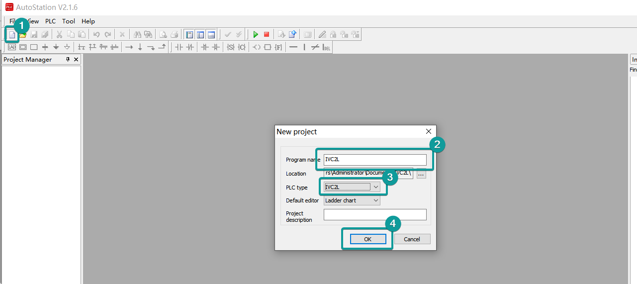
INVT
1)V-BOX setting
| Item | Settings | Note |
| Protocol | INVT_IVC2L | |
| Connection | RS232 | |
| Baud rate | 19200 | |
| Data bit | 8 | |
| Parity | EVEN | |
| Stop bit | 1 | |
| PLC station No. | 1 |
2)Address List
| Type | Device registers | Format | Range | Note |
| Bit | X | XOOO | 0~377 | |
| Y | YOOO | 0~377 | ||
| M | MDDDD | 0~1999 | ||
| SM | SMDDD | 0~255 | ||
| S | SDDD | 0~991 | ||
| T | TDDD | 0~255 | ||
| C | CDDD | 0~255 | ||
| Word | D | DDDDD | 0~7999 | |
| SD | SDDDD | 0~255 | ||
| Z | ZDD | 0~15 | ||
| T | TDDD | 0~255 | ||
| C | CDDD | 0~199 | ||
| Double word | C | CDDD | 200~255 |
3)Communication Settings

4)PLC software

5)PLC setting
Open the INVI plc software, create a new project or open a project that has already been created
Configure serial port parameters.

PC connect PLC

Download

6)Cable Wiring

Modbus
MODBUS RTU Slave (All function)
Select the protocol "Modbus RTU Slave (All Fuction)",
Then set baud rate, port, stop bits, data bits, parity.

Modbus Meter
The following example is using the Linfee meter LNF96EY to demonstrate how to set up the Modbus communication.
1. Wiring the RS485 cable first. Because the pin 58 is A, the pin 59 is B for meter. Here we use the COM1 to connect. So the diagram like follows:

2. Check the specific Modbus parameter in the communication menu from LED display.
So from the following pictures, we can know the Meter Address is 85, Baud rate is 9600, CRC None.

3. Set up the communication in the Configuration tab.
Select the protocol as ModBus RTU Slave (All Function). And set the communication parameters like below.

4. Create new real-time monitoring tag accroding to Modbus manual
Enter the address we want to read from the meter. The following table is intercept part of the manual for Linfee Modbus manual.
0x03/0x04 command data register address:
| Address | Description | Data Format | Data Length(Word) | Remark | |
|---|---|---|---|---|---|
| HEX | DEC | ||||
| 0x00 | 0 | Reserved | |||
| 0x02 | 2 | Reserved | |||
| 0x04 | 4 | Reserved | |||
| 0x06 | 6 | Ua | float | 2 | Phase Voltage data, Unit V |
| 0x08 | 8 | Ub | float | 2 | Phase Voltage data, Unit V |
| 0x0A | 10 | Uc | float | 2 | Phase Voltage data, Unit V |
| 0x0C | 12 | Uab | float | 2 | Line Voltage data, Unit V |
| 0x0E | 14 | Ubc | float | 2 | Line Voltage data, Unit V |
| 0x10 | 16 | Uca | float | 2 | Line Voltage data, Unit V |
| 0x12 | 18 | Ia | float | 2 | Phase Current data, Unit A |
| 0x14 | 20 | Ib | float | 2 | Phase Current data, Unit A |
| 0x16 | 22 | Ic | float | 2 | Phase Current data, Unit A |
For example, here we want to read the Phase Voltage Ua (Modbus offset 0006), the Modbus register main No. requires input decimal number, and check whether the actual address has one address offset, so the tag configured like the following screenshot:


Set the Modbus Slave Station No.

If the communication is setup successfully, the tag will show green light.

MODBUS RTU Master
Select the protocol "Modbus RTU Master",
Then set baud rate, port, stop bits, data bits, parity

address list
| Type | Data Type | Function code and description |
|---|---|---|
| Word | 3 | 04 (Read Input Registers: Read the current binary value in one or more input registers) |
| 06 (write single register: write a binary value to a holding register) | ||
| 10 (write values to multiple addresses ) | ||
| 4 | 03 (read holding register: read current binary value in one or more holding registers) | |
| 06 (write single register: write a binary value to a holding register) | ||
| 10 (write values to multiple addresses ) | ||
| W6 | 03 (read holding register: read current binary value in one or more holding registers) | |
| 06 (write single register: write a binary value to a holding register) | ||
| 10 (write values to multiple addresses ) | ||
| W16 | 03 (read holding register: read current binary value in one or more holding registers) | |
| 10 (write values to multiple addresses ) | ||
| Bit | 0 | 01 (Read coil state) |
| 05 (Force a single coil to force the on/off state of a logic coil) | ||
| 0F (Write multiple bits, ie write continuously) | ||
| 1 | 02 (Read the input state) | |
| 05 (Force a single coil to force the on/off state of a logic coil) | ||
| 0F (Write multiple bits) | ||
| W5 | 01 (Read coil state to obtain the current state of a set of logic coils) | |
| 05 (Force a single coil to force the on/off state of a logic coil) | ||
| 0F (Write multiple bits) | ||
| W15 | 01 (Read coil state to obtain the current state of a set of logic coils) | |
| 0F (Write multiple bits) |
MODBUS TCP Slave (All function)
Supported series: MODBUS TCP controller
V-B0X works as MODBUS TCP MASTER connecting with TCP SLAVE
1)V-BOX Setting
| Items | Settings | Note |
| Protocol | MODBUS TCP Slave (All function) | |
| Connection | Ethernet | |
| Port No. | 502 | |
| PLC station No. | 1 |
2)Address List
| Type | Data Type | Function code & Description |
|---|---|---|
| Word | 3 | 04 (read input register: read current binary value in one or more input registers) |
| 06 (write single register: write a binary value to a holding register) | ||
| 10 (write values to multiple addresses ) | ||
| 4 | 03 (read holding register: read current binary value in one or more holding registers) | |
| 06 (write single register: write a binary value to a holding register) | ||
| 10 (write values to multiple addresses ) | ||
| W6 | 03 (read holding register: read current binary value in one or more holding registers) | |
| 06 (write single register: write a binary value to a holding register) | ||
| 10 (write values to multiple addresses ) | ||
| W16 | 03 (read holding register: read current binary value in one or more holding registers) | |
| 10 (write values to multiple addresses ) | ||
| Bit | 0 | 01 (Read coil state) |
| 05 (Force a single coil to force the on/off state of a logic coil) | ||
| 0F (Write multiple bits, ie write continuously) | ||
| 1 | 02 (Read the input state) | |
| 05 (Force a single coil to force the on/off state of a logic coil) | ||
| 0F (Write multiple bits) | ||
| W5 | 01 (Read coil state to obtain the current state of a set of logic coils) | |
| 05 (Force a single coil to force the on/off state of a logic coil) | ||
| 0F (Write multiple bits) | ||
| W15 | 01 (Read coil state to obtain the current state of a set of logic coils) | |
| 0F (Write multiple bits) |
3)Communication Settings
Configure V-BOX Ethernet IP in Networking Settings

Configure PLC Ethernet IP in Communication;

4)Cable Wiring
communicate with VB inverter
User define
More serial port script instruction,please refer manual:Lua script function--->3.Serial port operation
Read the temperature sensor.
the commond format is as beliow:
Send commond:01 03 02 00 00 03 04 73
Feedback commond:01 03 06 07 F7 0E 7E B7 35
Temperature data:07 F7,desimal = 2039,it means temperature is 20.39℃.
Humidity data:0E 7E,desimal = 3710, it mean humidity is 37.10%RH.
Script Demo:
--dosomething
openPlc()
end
function openPlc()
if obj then
-- If the serial port opened,then read/write data by timing
local wri = string.pack(">HHHH",0X0103,0X0200,0X0003,0X0473)
local arr = reading(wri)
-- if arr ~=nil then
if arr[1] ==33 and arr[2] ==v[2][2] and arr[3] ==v[2][3] then
local A = arr[4]*256
local B = A+arr[5]
-- addr_setword(v[1],B)
end
-- end
else
--judge if there is a serial object, then initialize and open the serial port
local configs = {
name = 'COM1', --Select serial port COM1
mode = 485, --Communication mode RS485
baud_rate = 9600, --Baud rate 9600
stop_bit = 1, --stop bit 1
data_len = 8, --data length 8
check_bit = 'NONE', --no parity
}
obj,err = serial.open(configs) --Open serial port
if not obj then
print("serial open :failed", err) -- Open serial port failed
end
end
end
function reading(wri)
obj:flush() -- Clear serial port
obj:write(wri)-- Write serial port
print(string.byte(wri,1,#wri))
obj:flush() -- Clear serial port
local readed =obj:read(9,1000) -- Read 9 bytes, timeout 1 second
if readed and readed ~= "" then
-- judge that a non-empty string is read
print(string.byte(readed,1,#readed))
a={string.byte(readed, 1, #readed)}
if nil ~= a[4] and nil ~= a[5] and nil ~= a[6] and nil ~= a[7] then
a1=a[4]*256+a[5]
a2=a[6]*256+a[7]
addr_setword("@HDW0",a1)
addr_setword("@HDW1",a2)
end
return {string.byte(readed, 1, #readed)}
elseif readed == nil then
print("serial read err:", err or "")
return nil
end
return nil
end