2.03 Device Management
2.3 Device Management
Device management mainly includes device access, group management, viewing the data information and switch status collected by each device, alarm configuration status display, historical data query and basic interface control information.
Main functional module areas: "device source, toolbar, device search bar, share with others list, device watchlist, device list".

2.3.1 Mode switch
The mode switch button is in the upper right corner of the device management page. It is used to switch the display mode of the right area of the device management. There are "Dashboard Mode" and "Classic Mode". As shown in the figure below.

2.3.2 Multi-level device List
Multi-level device list module: displays all V-Boxes (collection gateways) or IoT HMIs under the account, and displays them in a multi-level grouped tree menu format.
After choosing the V-Box device, user will automatically jump to the device dashboard (dashboard mode) or device function module interface (classic mode),including eight modules: "Data Monitoring, Alarm Records, Historical Data, Cloud SCADA, Lua Script, and Basic Configuration."
Dashboard mode, as shown in the figure below.

Classic mode, as shown in the figure below.

After choosing IoT HMI device, user will automatically jump to the functional module interface, including six modules: "Remote Monitoring, Data Monitoring, Cloud SCADA, and basic information".
Dashboard mode, as shown in the figure below.

Classic mode, as shown in the figure below.

2.3.4 Tool bar
The following figure shows the button set for operating the V-Box/IoT HMI and device list, namely "Add device, Request to share, Filter, Group management, Refresh".

2.3.4.1 Add device
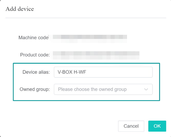
After registering a new account, you can add devices to bind to the account. One device can only be bound to one account.
When binding the V-Box/IoT HMI, you need to know the machine code and password of the V-Box/IoT HMI, enter the V-Box/IoT HMI device alias and select the group of the added V-Box/IoT HMI. If the administrator has created device groups, you can also choose to place the added devices under other groups, as shown in the figure below.

Supports adding multiple machine codes and product codes at one time. If the addition is successful, the corresponding device information will appear in the device list. If it fails, the specific failed device and the reason for the failure will be prompted.
2.3.4.2 Request to share
Request to share the V-Box/IoT HMI. After the other party agrees, the device requested to be shared will be displayed in the "Shared by Others" list in my account.
①Request to share: Click the request to share icon and enter the V-Box/IoT HMI machine code or product code, as shown in the figure below.

②The system will send a request to share to the "other device account" and wait for the other party to [agree/reject], as shown in the figure below. (Other people's account)

③The other party agrees to share, the sharing is successful and can be viewed in the [Others' Sharing List], as shown in the following figure.
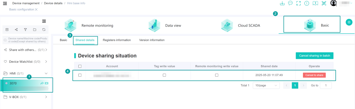
④Cancel sharing: [Basic Configuration] → [Sharing Details] → [Cancel Sharing] on the device, as shown below. (Other people's accounts)
2.3.4.3 Group management
Group management is a function for grouping the V-Box/IoT HMI. Administrators can manage the V-Box/IoT HMI groups, including adding groups, editing groups, and deleting groups, as shown in the figure below.
- When create a new group, the group can only be nested up to five levels.
- There is a default group for newly registered accounts.
- If a device group exists and cannot be deleted, a group with the same name can be created.

When adding a group, if you select the parent group, the new group will be created under this group. If it is not checked, it will be a first-level group, displayed on the outermost layer, as shown in the figure below.

2.3.4.4 Refresh
Click the [Refresh] button to refresh the device list, as shown in the figure below.

2.3.4.5 Filter
Click the [Filter] button to display the filter pop-up window, as shown in the figure below. Select the device filter range and click [OK].

2.3.5 Device search bar
Supports searching for devices by "machine code, product code and device name", supports fuzzy search, click ‘’Enter‘’ to perform the search, and the group will automatically close when searching, and the results will be displayed after the group name, as shown in the figure below.
Note: Device lists shared by others are not included in the search.

Search all the V-Boxes/IoT HMIs in the list according to the search conditions, and display all devices that meet the conditions.

2.3.6 Share with others list
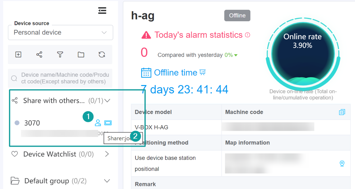
The share with others list shows a list of all V-Boxes/IoT HMIs shared by other accounts to your account. You can view the data under all V-Boxes/IoT HMIs, but you cannot modify the configuration of the V-Boxes/IoT HMIs.
Only the sharer can cancel the sharing of the V-Box/IoT HMI, and the sharee cannot cancel the sharing. When you move the mouse to the "human" icon , you can view the sharer, as shown in the figure below.
2.3.7 Device watchlist
The device watchlist shows the V-Box/IoT HMI that the current account follows, and the information in the V-Box/IoT HMI can be viewed and modified.
In the device watch list, you can unwatch the device by right-clicking the V-Box/IoT HMI. At the same time, the right-click menu will appear with “Unfollow” function, as shown in the figure below.

2.3.8 Device list
The device level icons are shown in the figure below.

The device level status description is as shown below.

The device status description table is as follows:
| Color | Color value(HEX) | Status |
|---|---|---|
| # 18E600 | Online | |
| # B5C1D8 | Offline | |
| # 1C9BFD | Throughing | |
| # 005CFF | VPN throughing | |
| # FD8B09 | VPN through reconnecting | |
| # 2C405E | VPN through ending | |
| # 109A00 | Ready for normal downloading | |
| # 009577 | Normal downloading |
2.3.8.1 Group right-click menu
When the mouse is on the group name of a multi-level group, right-click the mouse to display a drop-down menu bar, including the functions of adding devices, changing names, and maps, as shown in the figure below.

- Add device: Add V-Box/IoT HMI to add a new V-Box/IoT HMI to this group.
- Change name: Change group name.
- Map: Click to jump to the map monitoring page to query all devices under the clicked group.
2.3.8.2 Device right-click menu
When the mouse is on a certain V-Box/IoT HMI, right-click the mouse to display a drop-down menu bar, which includes functions such as "Follow, Move Group, Share Device, Copy Machine Code/Product Code, Transfer, Replace", as shown in the figure below.

(1) Follow/Unfollow
In the device list, you can follow the V-Box/IoT HMI that is not shared by others through the right-click menu. The right-click menu will show the function. After the V-Box/IoT HMI is followed, the follow mark and the move icon
 will appear on the right, indicating that the V-Box/IoT HMI has been followed.

(2) Move Group
Modify the group to which the device belongs, as shown in the figure below.

(3) Share Device
Share the device with permission (read and write) to other accounts. After sharing, the device will still be in your own device list, and other accounts can view it without receiving it.
Choose the device to be shared in the device list, right-click the menu bar and choose [Share device] to share the device, as shown in the following figure.

After sharing successfully, check the sharing details in [Basic Configuration], as shown below.

(4) Copy Machine code/Product code
Copy the machine code or product code of this device. (If the device has a product code, copy the product code first.)
(5) Transfer
If during the usage of the V-Box/ig device, the technician in charge of management changes, and it is necessary to transfer the IoT product to other personnel for management, the "Transfer" function can be used to transfer the device to another person for testing. During the transfer process of the V-Box/ig device, the configuration information of the device itself will not be affected, only the person in charge of management will be changed.
V-Box/ig IoT HMI Transfer: Transfer the V-Box/ig IoT HMI from one account to another. Except for the user changing, other information of the V-Box/ig IoT HMI will not change. When removing the V-Box/ig IoT HMI, enter the information of the transferring user and the password of the V-Box/ig IoT HMI. If the information is correct, the information of this account will appear, confirm the information of the other account is valid and then transfer.
①Locate the V-Box/IoT HMI in the device column. Right-click with the mouse → a drop-down box will pop up. Click the [Transfer] button as shown in the figure.

②Enter the "User information transferred and the password of the V-Box/IoT HMI", If the information is correct, the information of this account will appear, confirm the information of the other account is valid and then transfer. As shown in the following figure.

③V-Box/IoT HMI transfer has been completed successfully. Wait for the receiving party to confirm the receipt. As shown in the following figure.

④Receiving device: Log in to the receiving account, click the prompt box in the upper right corner of the page, find the V-Net 2.0 device to be transferred in the transfer device, and confirm the receipt, as shown in the figure below. (Other people's account)

⑤Reset the "Device Name" and select the "Device Group". (Other people's account)
⑥Prompt that the device is successfully bound, indicating that the V-Box/IoT HMI has been successfully transferred.
(6) Replace
When the V-Box device has an abnormality and needs to be replaced, you can choose the "Replace" function. Replace the old device with the new one, and update the configuration information of the old device to the new one at the same time, without reconfiguring. Please note that the new and old devices must be of the same model to complete the replacement action.
Example: Under this account, a new V-Box (same model) will be used to replace the old one. There are two V-Boxes, V-Box A is bound to the account. When V-Box A breaks down, " V-Box B" needs to replace " V-Box A" (V-Box B must be unbound). The following are the detailed steps for replacing a V-Box.
①V-Box device A is bound to a certain account. This description only takes this configuration information of the data monitoring interface as an example.
②Find V-Box A in the device column, right-click to pop up the drop-down box, and click the Replace button, as shown in the figure below.

③In the replacement interface, enter the machine code of V-Box B and the V-Box device password (default 888888), and click Replace, as shown in the figure below.

④During the replacement process, you will be prompted whether to continue replacing the V-Box device machine code. Click [OK] to replace the V-Box device, as shown in the figure below.

⑤After prompting that [Device A] is replaced successfully. V-Box B has completely replaced V-Box A successfully. Except for the machine code, the configuration information remains unchanged (compared with the data monitoring interface of "Step ①"), as shown in the following figure.

⑥Now, just take down the " V-Box A" on the equipment cabinet and install the " V-Box B" to complete the replacement, and the previous equipment operation can be carried out normally.
(7) Share Configuration
Share the configuration of the V-Box in the form of a sharing code. The sharing code needs to be set with a validity period. After clicking [Share Configuration], the sharing code for sharing the V-Box configuration will pop up, as shown in the figure below.

Other people's accounts: In the basic configuration, click the sharing code import button, verify the sharing code and import it into V-Box, as shown in the figure below.

(8) Export Configuration
Export the V-Box configuration. (The file is boxInfo.vbox)
(9) Import Configuration
Import the V-Box configuration. (The file is boxInfo.vbox)
(10) Import Template
Quickly configure data for the V-Box. You can select a configured template to import. After importing, the V-Box using this template will synchronize the configuration of the template's related data points and communication protocols. Its original configuration will be overwritten by the template's configuration. After clicking Import Template, a window for template selection will pop up. After selecting a template and clicking OK, the data of the selected template will be synchronized to the V-Box.

(11) Positioning
Manually modify device targeting.

(12) Cloud SCADA
Quickly jump to the cloud SCADA panel in the device.

(13) Generate a template
Generate a device template of the same device model based on the current device configuration.

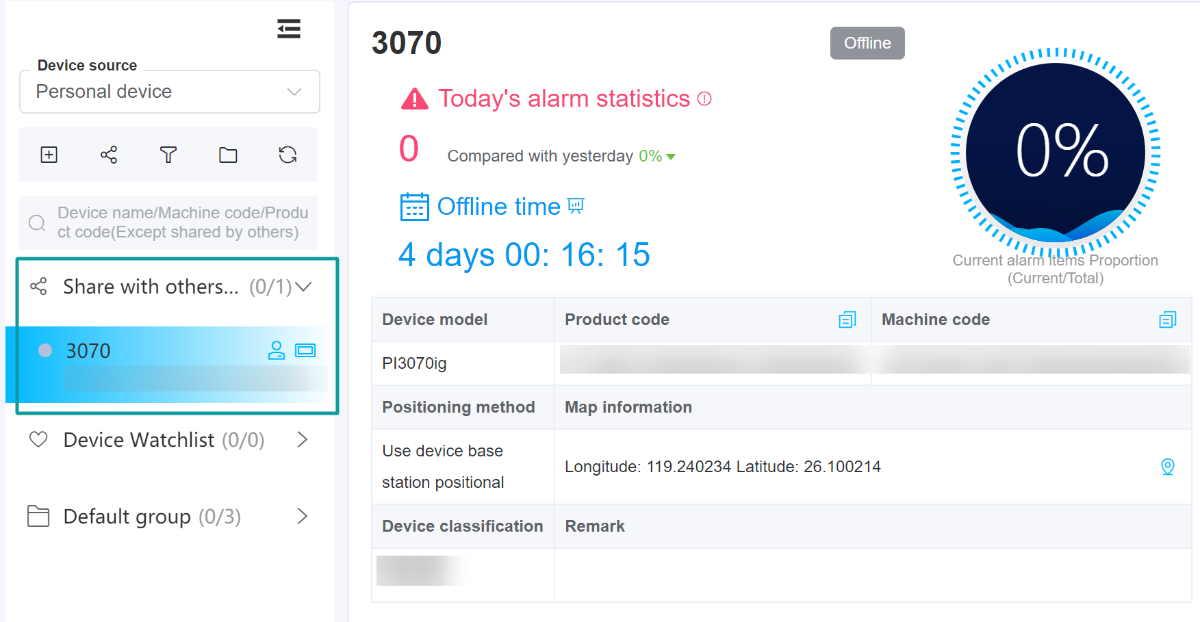
2.3.9 Device dashboard
The device dashboard consists of three blocks: "Device Basic Information Block", "Device Screen Collection Block" and "Device Data Block".
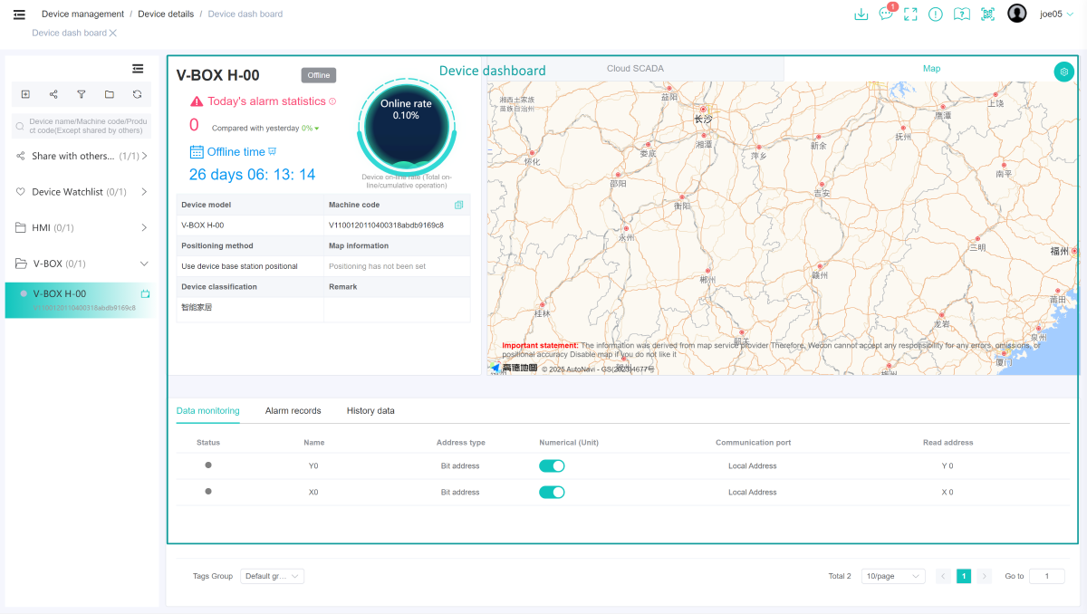
(1) Device basic information block
This block displays basic device details, and also provides alarm statistics and device online/offline duration statistics. Click the icon to view the device statistics for the online/offline period of the past week, month, or year. As shown in the figure below.

(2) Device screen collection block
This block provides remote monitoring (HMI) screens, cloud SCADA screens, and device map positioning for display device.
(3) Device data block
This block provides real-time monitoring of display data (V-Box), collection point information (HMI), device alarm records, historical data and maintenance tickets.
2.3.10 V-Box-Data monitoring
Data monitoring module, function buttons: add tags, add in batch, delete in batch, import/export, as shown below.

Data modification: On the data monitoring page, you can modify the real-time data of the monitoring point.
Click the text box in the "Value" column of a monitoring point in the list to enter the in-line editing state, enter the modified value, click "√" to modify, and modify the real-time data of the monitoring point to the input value, as shown in the figure below.

Through the menu bar at the top of the list, you can switch to view and operate the monitoring point data in different groups.

2.3.10.1 Add tags
Click [Add Tags] to add different types of data monitoring points for monitoring. The added monitoring points will be automatically refreshed in the monitoring list. The added monitoring points will be in the grouping of the current data list, without the need to select in the pop-up window, as shown below.

2.3.10.2 Add/Delete in batch
(1) Add in batch
The batch adding and adding monitoring points are the same operation, and multiple identical monitoring point data can be added at the same time. As long as you enter the quantity after [Batch count], the batch adding can be completed (monitoring point name: the serial number is added after the name by default), as shown in the figure below.

(2) Delete in batch
Choose the selection box at the head of the data list, select the data to be deleted, perform batch deletion, and delete all the selected monitoring points at one time.

2.3.10.3 Import/Export
Import: You can import external monitoring point information and monitoring points in the Excel table into the current group at one time. The content format in the file must be valid to import successfully. (The same monitoring points will be overwritten)
Export: You can export the selected monitoring point information to an Excel table. It also supports exporting all information at once and exporting template content.

2.3.10.4 Search
Support fuzzy query of monitoring points through "monitoring point name" and "address information"

2.3.10.5 Header menu bar
You can modify the information displayed in the header by clicking the button in the right header menu bar.

2.3.10.6 List action bar
- Edit: You can modify the information of existing monitoring points.
- Move: You can move the specified monitoring point information to other groups.
- Delete: Delete the current monitoring point.

2.3.11 V-Box-Alarm record
The alarm record page records all alarm records, including historical alarms and current alarms.
The current alarm is marked as a column showing the confirmation button, and the historical alarm is a confirmed button. After the current alarm is [confirmed], it will become a historical alarm.
2.3.11.1 Alarm details
In the conditional search area on the left side of the page, you can conduct a joint query on all alarm information, as shown in the figure below.

After clicking [OK], the alarm data will be converted into a historical alarm.
2.3.11.2 Alarm registration
The alarm registration displays the manually added alarm information, and the information can be "edited" and "deleted".

Click the [Alarm Registration] button to add new operations to the alarm registration. When adding an alarm registration, you need to select or enter data such as name, group, connection device (i.e. communication port), address type, etc., as shown in the figure below. As long as the value of the device monitoring point reaches the trigger condition, the corresponding alarm record will be generated.

2.3.11.3 Alarm setting
After checking, monitoring data push is suspended. If an alarm message is generated, no third-party platform reminder will push (default is on, keep pushing status), as shown in the figure below.

2.3.12 V-Box-History data
2.3.12.1 Raw data
In the raw data page, you can query the historical data, select grouping, input monitoring points, start and end dates and other conditions to search and query. The display of historical data can be viewed in two ways: "list and curve".
Batch deletion: You can check the box in front of the data to select the data and perform batch deletion.
Export to excel: Export the content as an excel table by customizing the number of export items.

2.3.12.2 Data registration
Data registration page displays the manually added data information, and the information can be "edited" and "deleted".
Group settings: You can "add and delete" groups and modify group information. Groups do not support the same name, as shown in the figure below.

①Click [Group Settings] → Click the [Add] button to add a historical data group, as shown in the figure below.

②Click the [Data Registration] button to add a piece of data. When adding data registration, you need to choose or enter the name, group, connection device (i.e. communication port), address type and other data, as shown in the figure below.

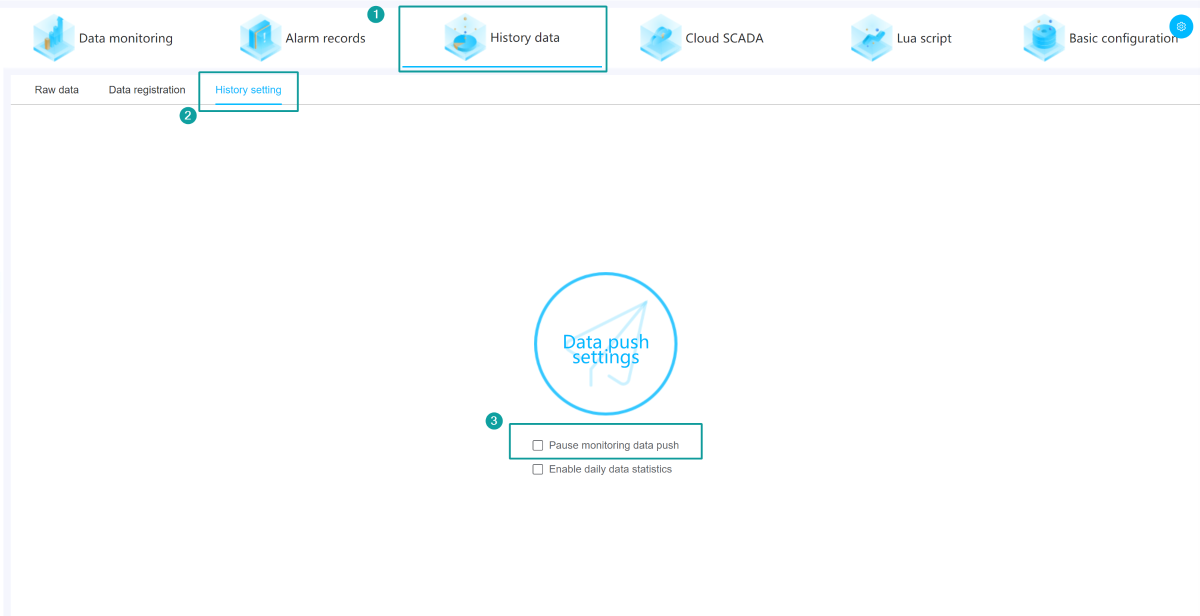
2.3.12.3 History setting
After checking, monitoring data push is suspended. If historical messages are generated, no third-party platform reminders will push (default is on, keep pushing status), as shown in the figure below.
2.3.13 V-Box-Lua script
2.3.13.1 Script management
Select [Lua script] of the V-Box device to enter the script management module of the V-Box device.
The script management module includes: script list, create script, edit script, delete script, batch delete script, synchronize script, batch synchronize script, import script, export script, debug, view V-Box script and other functions, as shown in the figure below.

(1) Create a new script
1) Create a script
Click the [New script] button, enter the name and execution strategy of the script, save and go to the next step to create a new script, as shown in the figure below.

Name: Enter the script name. The script name must start with a letter, be up to 32 characters, and do not support Chinese.
Strategy: Select the script execution condition. The script execution conditions include the following:
| Strategy | Function | Quantity |
|---|---|---|
| Initialization execution | Execute after the box is powered on, and only execute once. | Up to 1 |
| Execution if connected | Execute after the box is connected to the server. | Up to 1 |
| Execution if unconnected | Execute when the box is disconnected from the server. | Up to 1 |
| Timed execution | Timed execution Execute in a loop according to the set timer time. | Up to 5 |
Timing: When the script execution condition is timed execution, you need to enter the time and time unit for the timed execution.
The time unit can be selected from "days, hours, minutes, seconds, milliseconds", and the timing time must be greater than 1000 milliseconds and cannot exceed 1 day. After ensuring that the information is filled in correctly, click [Next] to generate a new script.
Information
2) Edit Lua
①Enter the Lua script editing interface, and the initialization code will be displayed in the script editor, as shown in the figure below.

--dosomething
end
②The Lua script edited by the user will be edited in the initialized function structure, and the structure is not allowed to be modified.
③The use of the script editor will be introduced in the [2.3.13.2 Script Editor] section
(2) Script list
After the script is successfully added, it will be displayed in the script list. One line represents one script.
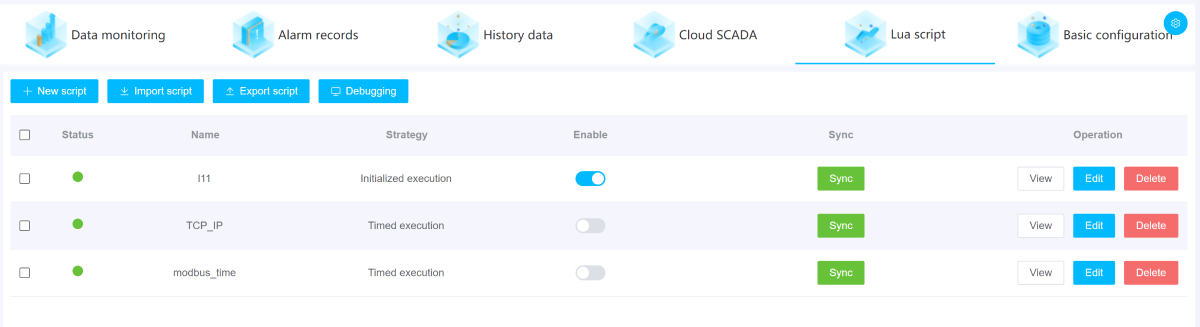
The script parameter description in the script list is as follows:
| Word | Description |
|---|---|
| Status | Indicates whether the script is synchronized. The status is divided into synchronized and unsynchronized. |
| Name | Script name. |
| Strategy | The execution conditions of the script. |
| Enable | The script enable switch. ON enables the script, OFF disables the script. When the box is offline or passing, the button is grayed out and inoperable. |
| Sync | Synchronize the script to the V-Box. When the script synchronization fails, a message will pop up, and you can click Details to view the failure information. When the box is offline or passing, this button is grayed out and inoperable. |
| Operation | Script view, delete and edit. |
(3) Script delete
Click the Delete button to delete a single script.
Select multiple scripts and click Delete in batch in the button bar of the script list to delete the selected scripts
(4) Script edit
Click the Edit button in the operation box of the script list to edit the script.
Next: Edit Lua script.as shown in the figure below.
(5) Sync in batch
Select the required script in the list and click the Sync in batch button in the button bar of the script list to synchronize the selected scripts. When the script content is wrong and enabled, after clicking the Synchronize button, the compilation failure information will be displayed next to the Synchronize button. Click Details to view the specific error content.
(6) Import/Export script
①Export script: Click [Export Script] in the button bar above the list to export all scripts of the current V-Box as files with a .script extension.
②Import script: Click [Import Script] in the button bar above the list to import an external script file with a .script extension into the V-Box. After importing the script, the script of the current V-Box will be cleared, as shown in the figure below.

(7) Debug
Click the [Debug] button in the button bar above the list to enter the script debugging page of the V-Box, as shown in the figure below.

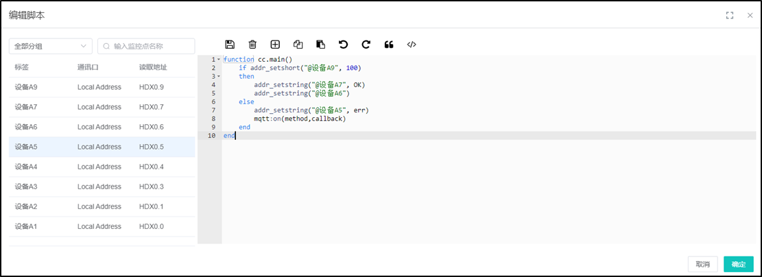
2.3.13.2 Script Editor
The script editor is an online editor for user to write Lua scripts.
Click [Next] in the pop-up window for adding or editing script to switch to the script editor page and write the Lua script of the V-Box. The functional divisions in the script editing page are shown in the figure below.

(1) Tag List
①This area lists all monitoring points of the current V-Box and has the function of searching for monitoring points.
②Click a monitoring point in the list to insert the monitoring point at the current cursor position of the script editor. The inserted monitoring point will have the @ symbol added to the name and defined as a string. For example, "@ Temperature of City A ". After synchronizing, the monitoring point variable will be converted into an address on the server and sent to the V-Box.
(2) Toolbar
The toolbar is in the top of the script editor, as shown in the figure below.

From left to right:
① Save: Save the current code.
② Clear: Clear the current code in the script editor. And restore to the initialization structure.
③ Insert address: Insert a new bit address or word address at the current cursor.
④ Copy: Copy code, shortcut key [ctrl+c]. For some lower version browsers (such as IE8 and below), content may not be copied outside the editor. It is recommended to use the ctrl+c to copy.
⑤ Paste: Paste code, shortcut key [ctrl+v]. This button is limited to pasting text copied in the current editor. It is recommended to use the ctrl+v paste key combination.
⑥ Undo: Undo editor actions step by step.
⑦ Restore: Restore editor actions step by step
⑧ Comment: Comment or uncomment the code in the selected line.
⑨ Compare difference: Two code editing areas can be opened, with the currently edited script displayed on the left and the last saved code displayed on the right.
(3) Code Editing Area
The editor has functions such as syntax verification, keyword prompts, common code snippet prompts, variable prompts, code completion, etc. It also provides monitoring point management functions, which can directly insert addresses as variables in the code.
①Syntax Verification
When writing Lua code, you can check the syntax validity in real time. An icon will appear next to the syntax error line. When you move the mouse over it, the error content will be prompted. When multiple lines are wrong, it will be displayed on the first line with the error. After resolving the error in the line, it will be displayed on the next error line.
Error example: [6:0] ‘do’ expected near ‘doo’, which means that ‘do’ is expected to be entered at the 0th character position of the 6th line. Syntax checking includes the following categories:
A: Check the spelling of keywords.
B: Check the definition of variables.
C: Check the usage specifications of operators.
D: Check the syntax of the function structure.
Note: The above syntax check does not include runtime error checking. Runtime error checking is to send the code to the V-Box and return the error information after the V-Box compiles it.

②Script Prompt
When writing code, it provides prompts such as fuzzy matching keywords, defined variables, code snippets, etc. Click the corresponding prompt line to complete the code, as shown in the figure below.

The provided hint codes and complete codes include the following categories:
A: Keywords, keywords of Lua language, built-in method names, built-in constants, and library functions.
B: Code snippets, commonly used code snippets of Lua
C: Defined variables (local), all defined variable names.
| Name | Sample Code | Function |
|---|---|---|
Code snippets
| local x = 1 | Variable Definition |
function fname(...) -- body end | Function structure | |
for i=1,10 do print(i) end | for loop structure | |
while (condition) do -- body end | while loop structure的 | |
if (condition) then -- body end | Conditional structure | |
| method names | _G|_VERSION|assert|collectgarbage|dofile|error|getmetatable|ipairs|" + "load|loadfile|next|pairs|pcall|print|rawequal|" + "rawget|rawlen|rawset|require|select|setmetatable|" + "tonumber|tostring|type|xpcall|create|isyieldable|resume|running|" + "status|wrap|yield|debug|gethook|getinfo|getlocal|" + "getmetatable|getregistry|getupvalue|" + "getuservalue|sethook|setlocal|setmetatable|setupvalue|setuservalue|traceback|upvalueid|upvaluejoin|" + "abs|acos|asin|atan|ceil|cos|deg|exp|" + "floor|fmod|huge|log|max|maxinteger|min|mininteger|" + "modf|pi|rad|random|randomseed|sin|sqrt|tan|" + "tointeger|type|ult|clock|date|difftime|time|config|cpath|" + "loaded|loadlib|path|preload|searchers|searchpath|byte|char|dump|" + "find|format|gmatch|gsub|len|lower|match|pack|packsize|rep|reverse|" + "sub|unpack|upper|concat|insert|move|pack|remove|sort|unpack|charpattern|" + "codepoint|codes|offset|" + "foreachi|maxn|foreach|concat|remove| | |
| built-in constants | true|false|nil|_G|_VERSION |
2.3.14 V-Box-Basic configuration
The basic configuration of V-Box is mainly included: Basic information configuration, Shared details, Communication port configuration, Network configuration, Data limit, Registers information, Version information.
Basic information configuration: Manage the name, longitude and latitude of the V-Box, and support advanced functions such as unbinding and restarting.
Shared details: Display the sharing status of the device.
Communication port configuration: Can add, delete, edit communication port information, and manage the label of the communication port.
Data limit: View the current data restriction information, which can only be viewed but not modified.
Version information: Display the firmware information, and can check for updates and upgrade the firmware version.
Network configuration: Configure network information.
Registers information: View the current register information, and support to modify time and password.

2.3.14.1 Basic information configuration
In the "Basic information configuration" sub-page of the basic configuration of the V-Box, you can manage the V-Box information, such as modifying the name, longitude and latitude, and remarks of the V-Box. After the user enters the modified information, click the [Save Changes] at the bottom, and the entered data must be valid for the modification to be successful. The basic information management interface of the V-Box is shown in the figure below.

(1) Unbind the device
Click [Unbind the device] → [OK] to unbind. After unbinding, the device will be invisible.

(2) Device restart
Click [Device restart] → [OK] and the device will physically restart.

(3) Force to sync
Click [Force to sync] → [OK], and the device will synchronize the configuration to V-Box.

(4) Copy configuration
Copy configuration: Copy the configuration information of the V-Box from one V-Box to another (“Copy Configuration” can only be performed when there are same model V-Boxes under the account)
If the configuration information of multiple V-Boxes is the same, you can configure the information of one V-Box first, and then use the [Copy Configuration] function to copy the configuration parameter information to another V-Box, as shown in the figure below.

(5) Import configuration
Import configuration for this V-Box. (boxInfo.vbox)
(6) Export configuration
Export the V-Box configuration. (boxInfo.vbox)
(7) Share configuration
Share the configuration of the V-Box in the form of a sharing code, and the sharing code needs to be set with a validity period. After clicking [Share Configuration], the sharing code will pop up, as shown in the figure below.

Other people's accounts: In the basic configuration, select the sharing code import button, verify the sharing code and import it into V-Box, as shown in the figure below.

(8) Sharing code import
In the basic configuration, select the sharing code import button, verify the sharing code and import it into V-Box.
(9) Import template
You can import a template to quickly configure V-Box. After importing, the V-Box will synchronize the configuration of the template's data points and communication protocols, and its original configuration will be overwritten by the template's configuration. After clicking Import Template, select a template in the Template Selection pop-up window and click OK, and the data of the selected template will be synchronized to the V-Box.
2.3.14.2 Shared details
Display the sharing status of the device. You can modify the sharing permission (read and write) settings and cancel sharing, as shown in figure below.

2.3.14.3 Communication port configuration
In the [Communication port configuration] interface under [Basic configuration], you can perform the "add, modify and delete" operations of the communication port configuration. Only admin account has the authority to operate this function.
①Add communication port: Select or enter the communication protocol, device type, driver name, device station number, PLC station number and other information. After the communication port is configured successfully, the system will synchronize the configuration and driver files to the V-Box in 30 seconds.
②Modify the communication port: The admin account can modify the data except the V-Box ID. If the driver file is changed, the monitoring points and data under this communication port will be deleted, as shown in the figure below.

③Delete communication port: After deletion, the monitoring points and data under this communication port will be deleted; When deleting the communication port, a prompt dialog box will pop up to confirm whether to continue the operation.

2.3.14.4 Data limit
Record the data monitoring, history registration, and alarm registration of the current V-Box, as shown in the figure below:

2.3.14.5 Version information
You can view the version information of the V-Box in the [Version information] interface of [Basic configuration]. You can judge the function of the V-Box based on the version information, as shown in the figure below.

2.3.14.6 Network configuration
You can check the network configuration information and modify the networking mode of the V-Box, etc., as shown in the figure below.

2.3.14.7 Registers information
Record the device information of the V-Box, modify the access password, and display the device IP address, WIFI, 4G and other information, as shown in the figure below.

2.3.15 HMI-Remote monitoring
Remote monitoring displays the configuration engineering screen of the current HMI, as shown below.

2.3.16 HMI-Data view
The data view module includes: Communication port information, Collection point, Alarm configuration information, Alarm data information, Historical configuration information, and History data information, as shown in the figure below. (All data is collected from HMI, and data points and other information cannot be added)

2.3.16.1 Communication port information
View the device's communication port, connection mode, agreement name and other information. (View only)

2.3.16.2 Collection point
View the device's data. (View only, not configurable, values can be modified)

2.3.16.3 Alarm configuration information
View the device's configuration alarm information. (View only)

2.3.16.4 Alarm data information
View the device's current alarm information.

After clicking [OK], the alarm data will be converted into a historical alarm.
2.3.16.5 Historical configuration information
View the device's data. (View only)

2.3.16.6 History data information
View the device's data. (View only)

2.3.17 HMI-Basic
The basic information includes: "Basic , Shared Details, Registers information, and Version information" .
2.3.17.1 Basic
The HMI information can be managed, such as modifying the HMI name, IoT HMI record keeping, latitude and longitude, and remarks. After the user enters the modified information, user needs to click the [Saved] at the bottom, and the entered data must be valid for the modification to be successful, as shown in the figure below.

(1) Unbind the device
Click [Unbind the device] → [OK] to unbind. After unbinding, the device will be invisible.

(2) Device restart
Click [Device restart] → [OK] and the device will soft restart.

2.3.17.2 Shared details
Display the sharing status of the device. You can modify the sharing permission (read and write) settings and cancel sharing, as shown in figure below.

2.3.17.3 Registers information
Record the device information of the HMI, modify the access password, and display the device IP address, WIFI, 4G and other information, as shown in the figure below.

2.3.17.4 Version information
Get the version information of the HMI and determine the function of the HMI based on the version information, as shown in the following figure.

2.3.18 HMI/V-Box-Cloud SCADA
![]()
The main functions of the cloud SCADA interface are described as follows:
 Refresh current Cloud SCADA project
 Browse the current Cloud SCADA project in full screen (ESC to exit)
 Switch the bound Cloud SCADA project, as shown in the following figure.
 Edit current Cloud SCADA project (Jump to the project editing page)
