03 Installation
Overall structural drawing
Unit: mm
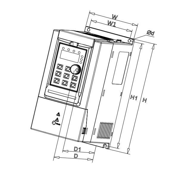
Figure 2-1-1 0.75kW-7.5kW outline dimension diagram
| AC Drive Model | Overall Dimensions | Mounting Hole | Mounting Hole Diameter | ||||
| H | W | D | D1 | H1 | W1 | d | |
| VB-2SR75GB | 187 | 88 | 138 | 130 | 177 | 73 | 5 |
| VB-2S1R5GB | |||||||
| VB-2S2R2GB | |||||||
| VB-4TR75GB | |||||||
| VB-4T1R5GB | |||||||
| VB-4T2R2GB | |||||||
| VB-4T004GB/5R5PB | 207 | 100 | 147 | 139 | 197 | 85 | 5 |
| VB-4T5R5GB/7R5PB | 247 | 130 | 167 | 159 | 237 | 113 | 5 |
| VB-4T7R5GB | |||||||
Table 2-1-1 0.75kW-7.5kW outline dimension

Figure 2-1-2 11kW-110kW outline dimension diagram
| AC Drive Model | Overall Dimensions | Mounting Hole | Mounting Hole Diameter | ||||
| H | W | D | D1 | H1 | W1 | d | |
| VB-4T011GB/015PB | 348 | 182 | 211 | 196 | 331 | 156 | 6 |
| VB-4T015GB/18R5PB | |||||||
| VB-4T18R5GB/022PB | 373 | 220 | 205 | 190 | 356 | 156 | 6 |
| VB-4T022GB/030PB | |||||||
| VB-4T030G/037P | 435 | 256 | 222 | 208 | 419 | 170 | 6 |
| VB-4T037G/045P | |||||||
| VB-4T045G/055P | 543 | 310 | 280 | 265 | 523 | 245 | 10 |
| VB-4T055G/075P | |||||||
| VB-4T075G/093P | 580 | 358 | 328 | 314 | 560 | 270 | 10 |
| VB-4T093G/110P | |||||||
| VB-4T110G/132P | |||||||
Table 2-1-2 11kW-110kW outline dimension

Figure 2-1-3 132kW-400kW outline dimension diagram
| AC Drive Model | Overall Dimensions | Mounting Hole | Mounting Hole Diameter | |||||
| H | H2 | W | D | D1 | H1 | W1 | d | |
| VB-4T132G/160P | 1199 | 350 | 502 | 355 | 342 | 842 | 320 | 10 |
| VB-4T160G/185P | ||||||||
| VB-4T185G/200P | ||||||||
| VB-4T200G/220P | 1570 | 426 | 600 | 408 | 398 | 1147 | 400 | 12 |
| VB-4T220G/250P | ||||||||
| VB-4T250G/280P | ||||||||
| VB-4T280G/315P | ||||||||
| VB-4T315G/355P | 1696 | 426 | 800 | 408 | 398 | 1266 | 520 | 12 |
| VB-4T355G/400P | ||||||||
| VB-4T400G | ||||||||
Table 2-1-3 132kW-400kW outline dimension
Keypad and installation
Unit: mm
Keypad size
Two keyboards of different sizes are designed according to the power section.

Figure 2-2-1-1 Keypad size1
- Single-phase 220V: 0.75kW-2.2kW
- Three-phase 220V: 0.75kW-4kW
- Three-phase 380V/440V: 0.75kW-7.5kW)

Figure 2-2-1-2 Keypad size2
- Three-phase 220V: 5.5kW-7.5kW
- Three-phase 380V/440V: 11kW-400kW)
Keypad bracket
Unit: mm
| Power Range | Single-phase 220V :0.75kW-2.2kW Three-phase 220V :0.75kW-4kW Three-phase 380V :0.75kW-7.5kW | Three-phase 220V :5.5kW-7.5kW Three-phase 380V :11kW-400kW |
| Keypad bracket |
|
|


Table 2-2-2-1 Different bracket sizes of various power range keypad when being extended
Main circuit connection

0.75-22kW: Figure 2-3-1 Main circuit wiring diagram 1

More than 22 kW: Figure 2-3-2 Main circuit wiring diagram 2
| Terminal mark | Name | Description |
| R/L. S. T/N | Power supply input terminals | Connect to the AC power supply |
| ( + ). ( - ) | Positive and negative terminals of DC bus | Common DC busbar input terminal (Connect terminals for external brake units of 30KW and above) |
| ( + ). PB | Brake resistance connecting terminal. | Connect to the braking resistor |
| P.( + ) | Connecting terminals of DC reactor | Dc reactor connection terminal 30kW-110kW:External dc reactor 132kW-400kW:Built - in DC reactor |
| U. V. W | AC drive output terminals | Connect the three-phase motor. |
 | Grounding terminal | Must be grounded. |
Table 2-3-1 Main circuit terminals and function
Control circuit connection
Control terminal configuration 1

Figure 2-4-1-1 Control terminal diagram 1
Model reference:
- Single-phase 220V: 0.75kW-2.2kW
- Three-phase 220V: 0.75kW-4kW
- Three-phase 380V/440V: 0.75kW-7.5kW
Control terminal configuration 2

Figure 2-4-2-1 Control terminal diagram 2
Model reference:
- Three-phase 220V: 5.5kW-7.5kW
- Three-phase 380V/440V: 11kW-400kW
Control terminals&functions
| Category | Terminal symbol | Terminal name | Function description |
| Power supply | +10V-GND | +10V power supply | Provide +10V power supply to external unit. Generally, it provides power supply to external potentiometer with resistance range of 1-5 kΩ. Maximum output current: 20 mA |
| +24V-COM | +24V power supply | Provide +24V power supply to external unit. Generally, it provides power supply to DI/DO terminals and external sensors. Maximum output current: 150 mA | |
| OP | External power input terminal | Connect to +24V by default. When DI1-DI6 need to be driven by extemal signal, OP needs to be connected to external power supply and be disconnected from +24V. | |
| Analog input | AI1-GND | Analog input terminal 1 | 1. Input voltage range: 0-10V 2. Input resistance: 22 kΩ |
| AI2-GND | Analog input terminal 2 | 1. Input range: 0-10V/0-20mA, decided by jumper J2 on the control board. 2. Input resistance: 22 kΩ(voltage input), 500Ω(current input) | |
| Digital input | DI1 | Digital input 1 | 1. Optical coupling isolation, compatible with dual polarity input 3. Voltage range for level input: 9V -30V |
| DI2 | Digital input 2 | ||
| DI3 | Digital input 3 | ||
| DI4 | Digital input 4 | ||
| DI5 | Digital input 5 | ||
| DI6 | Digital input 6 | ||
| Analog output | AO1-GND | Analog output 1 | AO1: Voltage or current output is decided by jumper J1. Output voltage range: 0-10V Output current range: 0-20mA AO2: Output voltage range: 0-10V |
| AO2-GND | Analog output 2 | ||
| Digital output | FM-CME | Digital output/high-speed pulse output | open collector output Output voltage range: 0V -24V |
| Relay output | T1A-T1B | NC terminal | Contact driving capacity: AC 250V,3A,COSø=0.4; DC 30V,1A. |
| T1A-T1C | NO terminal | ||
| T2A-T2C | NO terminal | ||
| Communication port and socket | RS+ | RS485 signal positive terminal | |
| RS- | RS485 signal negative terminal | ||
Table 2-4-3-1 Control terminal instruction
Machine installation interval requirements
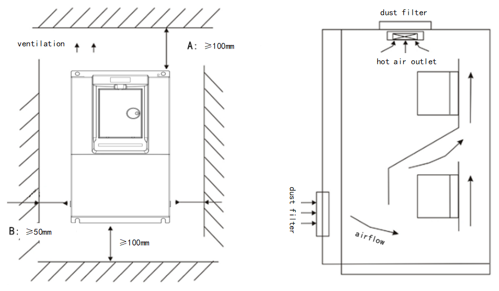
Note: The minimum installation distance of A is 100mm, and the minimum installation distance of B is 50mm; Reasonably increase the interval size as the power increases.