09 Function code
F0 group basic function group
| F0.00 | Motor control mode | Factory default | 1 |
| Setting range | 0: Speed sensorless vector control (SVC) 1: V/F control | ||
0: Speed sensorless vector control
Refers to an open loop vector. Suitable for the usual high-performance control occasions, one inverter can only drive one motor. Such as machine tools, centrifuges, wire drawing machines, injection molding machines and other loads.
1: V/F control
It is suitable for occasions where the load requirement is not high or a VFD drags multiple motors, such as fans and pumps. It can be used for driving multiple motors with one VFD.
Tip: When selecting the vector control mode, the motor parameter identification process must be carried out. Only accurate motor parameters can give full play to the advantages of vector control.
| F0.01 | Command source selection | Factory default | 0 |
| Setting range | 0: Operation panel command channel 1: Terminal command channel 2: Serial port communication command channel | ||
Select the channel for the inverter control command.
Inverter control commands include: start, stop, forward, reverse, point and so on.
0: Operation panel command channel
The command is controlled by the key on the operation panel.
1: Terminal command channel
It is controlled by the multi-function input terminals FWD, REV, FJOG, RJOG, etc.
2: Serial port communication command channel
The host computer gives the running command control through the communication mode.
| F0.02 | Run time UP/DOWN benchmark | Factory default | 1 |
| Setting range | 0: Operating frequency 1: Setting frequency | ||
This function only effective for frequency source digital setting, in order to determine the setting frequency of UP/DOWN is current running frequency or current setting frequency.
| F0.03 | Main frequency source X choice | Factory default | 4 |
| Setting range | 0: Digital setting F0.08 (Adjustable terminal UP/DOWN, be not retained at power failure) 1: Digital setting F0.08 (Adjustable terminal UP/DOWN, be retained at power failure) 2: AI1 3: AI2 4: Keyboard potentiometer set 5: Set the terminal PULSE 6: Multi-speed instruction 7: Simple PLC 8: PID 9: Communication settings 10: AI3(Expansion module) | ||
Select the input channel for the main given frequency of the inverter. There are 10 main given frequency channels:
0: Digital setting (no memory) (Potentiometer and terminal UP/DOWN adjustable, power failure no memory) The initial value is F0.08 value of Digital Setting Preset Frequency. The set frequency value of the inverter can be changed by ▲/▼ key of the keyboard (or the UP and DOWN of the multi-function input terminal). No memory means that after the inverter power off, the set frequency value is restored to the initial value;
1: Digital setting (memory) (Potentiometer and terminal UP/DOWN adjustable, power failure memory) The initial value is F0.08 "digital setting preset frequency" value. The set frequency value of the inverter can be changed by ▲/▼ key of the keyboard (or the UP and DOWN of the multi-function input terminal). Memory means that when the inverter is powered on again after power failure, the set frequency is the set frequency before the last power failure
2: AI1 3: AI2 refers to the frequency determined by the analog input terminal. The standard unit provides two analog input terminals (AI1, AI2), of which AI1 is 0V to 10V voltage input, AI2 can be 0V to 10V voltage input, or 4mA to 20mA current input.
4: Potentiometer set by keyboard potentiometer to set the frequency
5: PULSE pulse setting (DI4) The frequency setting is set by the terminal pulse. Pulse given signal specifications: voltage range, frequency range 0kHz to 20kHz. Note: Pulse Settings can only be input from the multi-function input terminal DI4.
6: Multi-speed Select the multi-speed operation mode. The F5 "input terminal" and FD "multi-speed and PLC" parameters need to be set to determine the correspondence between a given signal and a given frequency.
7: Simple PLC Select simple PLC mode. When the frequency source is a simple PLC, the FD group "multi-speed and PLC" parameters need to be set to determine the given frequency.
8: PID selection process PID control. In this case, set the PID function of the F9 group. The operating frequency of the inverter is the frequency value after PID action. For the meaning of PID set source, feed quantity and feedback source, please refer to the introduction of F9 group "PID Function".
9: Communication set means that the main frequency source is given by the host computer through communication.
| F0.04 | Auxiliary frequency source Y selection | Factory default | 4 |
| Setting range | 0: Numeric setting F0.08 (Terminal UP/DOWN can be change, Power failure does not remember. It is cleared after switching as a frequency source.) 1: Numeric setting F0.08 (Terminal UP/DOWN adjustable, be retained at power failure.) 2: AI1 given 3: AI2 given 4: Keyboard potentiometer set. 5: The terminal PULSE pulse is set. 6: Multi-speed instruction 7: Simple PLC 8: PID 9: Communication setting | ||
The secondary frequency source Y is used in the same way as the primary frequency source X when it is used as an independent frequency given channel (that is, the frequency source selected to switch from X to Y).
| F0.05 | The auxiliary frequency source Y range is selected during superposition | Factory default | 0 |
| Setting range | 0: Relative to the maximum frequency F0.10 1: Relative to the frequency source X | ||
| F0.06 | Auxiliary frequency source Y range in superposition | Factory default | 100% |
| Setting range | 0% to 150% | ||
When the frequency source is selected as a frequency stack (F0.07 is set to 1, 3, or 4), it is used to determine the adjustment range of the auxiliary frequency source. F0.05 is used to determine the object relative to the range, if it is relative to the maximum frequency (F0.10), the range is a fixed value; If it is relative to the primary frequency source X, its range will change as the primary frequency source X changes.
| F0.07 | Frequency source stack selection | Factory default | 0 |
| Setting range | LED bits: Frequency source selection 0: Primary frequency source 1: Results of primary and secondary operations 2: Master-auxiliary switching 3: Switch between primary frequency source and operation result 4: Switch between primary frequency source and operation result LED ten: combination mode selection 0: Primary + Auxiliary 1: Master-auxiliary 2: Maximum value of both 3: Minimum of both 4: Main x auxiliary | ||
The secondary frequency source is used in the same way as the primary frequency source X when it is used as an independent frequency given channel (that is, the frequency source selected is switched from X to Y). When the secondary frequency source is used as a superposition given (i.e., the frequency source selected is X+Y, X to X+Y switching, or Y to X+Y switching), there are the following special features:
When the auxiliary frequency source for digital or pulse potentiometer timing, preset frequency (F0.08) does not work, through the keyboard ▲/▼ key (or multi-function input terminal UP, DOWN) can be adjusted on the basis of the main given frequency.
When the auxiliary frequency source is given as an analog input (AI1, AI2) or a pulse input, 100% of the input setting corresponds to the auxiliary frequency source range (see F0.05 and F0.06 instructions). If you need to adjust up or down from the main given frequency, set the analog input to a range of n% to +n%.
The frequency source is timed for pulse input, similar to analog quantity setting.
Tip: The secondary frequency source Y and the primary frequency source X Settings cannot be the same, that is, the primary and secondary frequency sources cannot use the same frequency given channel.
| F0.08 | Keyboard setting frequency | Factory default | 50.00Hz |
| Setting range | 0.00 to Maximum frequency F0.10 | ||
When the frequency source is selected “Numeric setting F0.08 (Terminal UP/DOWN Adjustable, power down memory) ", the function code value sets the initial value for the frequency number of the inverter.
| F0.09 | Running direction selection | Factory default | 0 |
| Setting range | 0: The same direction 1: The direction is reversed 2: Reverse prohibition | ||
By changing the function code, the steering of the motor can be changed without changing any other parameters, which is equivalent to the conversion of the rotation direction of the motor by adjusting any two lines of the motor (U, V, W).
Tip: The motor running direction will be restored to the original state after parameter initialization. For the system debugging is strictly prohibited to change the motor steering occasions with caution.
| F0.10 | Maximum output frequency | Factory default | 50.00 Hz |
| Setting range | 0.00 to 320.00Hz | ||
When F0.26=1, the upper limit of the maximum frequency is 1000Hz. When F0.26=2, the upper limit of the maximum frequency is 320Hz.
| F0.11 | Upper limit frequency source selection | Factory default | 0 |
| Setting range | 0: The number is F0.12 1: AI1 2: AI2 3: AI3(Expansion module) 4: Set the terminal PULSE 5: Communication given 6: Reserved 7: Keyboard potentiometer set | ||
Define the source of the upper limit frequency.
0: Number setting (F0.12).
1/2/3: Analog input channel. When setting an upper limit frequency with an analog input, 100% of the analog input setting corresponds to F0.12.
4: Set by terminal pulse.
5: Communication given 10000 corresponds to F0.12.
7: Set by keyboard potentiometer.
For example, in torque control, speed control is not effective. In order to avoid the "speed" of material breakage, the upper limit frequency can be set with the analog quantity. When the inverter runs to the upper limit frequency value, the torque control is invalid and the inverter continues to run at the upper limit frequency.
| F0.12 | Upper limit frequency | Factory default | 50.00Hz |
| Setting range | Lower frequency F0.14 to Maximum frequency F0.10 | ||
| F0.13 | Upper frequency bias | Factory default | 0.00Hz |
| Setting range | 0.00Hz to Maximum frequency F0.10 | ||
When the upper limit frequency is given by the analog quantity, this parameter is used as the bias quantity calculated by the upper limit frequency, and this upper limit frequency offset is added to the set value of the upper limit frequency of the simulation as the set value of the final upper limit frequency.
| F0.14 | Lower frequency | Factory default | 0.00Hz |
| Setting range | 0.00Hz to Upper limit frequency F0.12 | ||
When the VFD starts to run, it starts from the start frequency. If the given frequency is less than the lower limit frequency during operation, the VFD runs at the lower limit frequency, stops or runs at zero speed. You can set which mode of operation to use with F0.15.
| F0.15 | Lower frequency Operating mode | Factory default | 0 |
| Setting range | 0: Run at the lower limit frequency 1: Stop 2: Zero speed operation | ||
Select the operating state of the inverter when the set frequency is lower than the lower limit frequency. In order to avoid the motor running at low speed for a long time, you can use this function to choose to stop.
| F0.16 | Carrier frequency | Factory default | Model determination |
| Setting range | 0.5kHz to 16.0kHz | ||
This function regulates the carrier frequency of the inverter. By adjusting the carrier frequency, the motor noise can be reduced, the resonance point of the mechanical system can be avoided, and the interference of the line to the floor drain current and the VFD can be reduced.
When the carrier frequency is low, the higher harmonic component of the output current increases, the motor loss increases, and the motor temperature rise increases.
When the carrier frequency is high, the motor loss decreases and the motor temperature rise decreases, but the VFD loss increases, the VFD temperature rise increases and the interference increases.
The effect of adjusting the carrier frequency on the following performance:
| Carrier frequency | Low  High High |
| Motor noise | High  Low Low |
| The output current waveform | Worse  Better Better |
| Temperature rise in electric motors | High  Low Low |
| VFD temperature rise | Low  High High |
| Leak current | Low High High |
| External radiation interference | Low High High |
| F0.17 | Carrier PWM baud selection | Factory default | 1010 |
| Setting range | Bits: Select PWM mode 0: Automatic switching; 1: 7 wave; 2: 5 wave; 3: SPWM; LED ten: Carrier is associated with the output frequency 0: Independent of the output frequency 1: Related to the output frequency LED hundred: random PWM depth 0: Off 1-8: Open and adjust the depth LED kilobit: Over modulation option 0: Off 1: On | ||
| F0.18 | Acceleration time 1 | Factory default | Model determination |
| Setting range | 0.0s to 6500.0s | ||
| F0.19 | Deceleration time1 | Factory default | Model determination |
| Setting range | 0.0s to 6500.0s | ||
One place: Select PWM mode
VFD can choose 5-section wave or 7-section wave, the 5-section wave converter has little heat, and the 7-section wave motor has little noise. When the bit is 0, 7 waves are generated at low frequency and 5 waves are generated at high frequency. At 1 o 'clock, the whole wave is 7 stages, and at 2 o'clock, the whole wave is 5 stages.
Tens place: The carrier is associated with the output frequency
When the output frequency is low, reducing the PWM carrier can increase the low frequency starting torque and reduce the electromagnetic interference during starting. When the bit is 1, the program automatically reduces the PWM carrier when the output frequency is low.
Hundreds place: Random PWM depth
In order to make the motor noise spectrum flatter, you can turn on the random PWM function, after the function is turned on, the PWM carrier is no longer a fixed value, but fluctuates around the F0.16 set carrier. When the bit is not 0, the random PWM function works. The larger the value, the wider the fluctuation range and the flatter the noise spectrum. It should be noted that after opening the random carrier, the electromagnetic noise of the motor will not necessarily be reduced, and the actual noise perception varies from person to person.
Thousands place: Over modulation option
The over modulation function can increase the maximum output voltage of the inverter, but it also makes the current distortion more obvious. When the bit is 1, the over modulation function is enabled.
Acceleration time refers to the time required for the inverter to accelerate from zero frequency to the reference frequency of acceleration and deceleration (determined by F0.24), as shown in t1 in Figure 9-0-1.
Deceleration time refers to the time required for the VFD to decelerate from the reference frequency of acceleration and deceleration (determined by F0.24) to the zero frequency, see t2 in Figure 9-0-1.

Figure 9-0-1 Acceleration and deceleration time
Note the difference between the actual acceleration and deceleration time and the set acceleration and deceleration time.
There are four groups of acceleration and deceleration time selection
Group 1: F0.18, F0.19;
Group 2: F8.03, F8.04;
Group 3: F8.05, F8.06;
Group 4: F8.07, F8.08.
The acceleration and deceleration time can be selected through the multifunctional digital input terminals (F5.00 to F5.03).
| F0.20 | Parameter initialization | Factory default | 0 |
| Setting range | 0: No operation 1: Restore factory default (Do not restore motor parameters) 2: Clear the record information 3: Restore factory default (Restore motor parameters) | ||
1: Restore factory settings, excluding motor parameters
2: Clear recorded information, clear the VFD fault record, cumulative running time (F7.09), cumulative power-on time (F7.13),
Cumulative power consumption (F7.14).
3: Restore all factory settings, including motor parameters, and clear the recorded information at the same time.
| F0.23 | Unit of acceleration and deceleration time | Factory default | 1 |
| Setting range | 0: 1s 1: 0.1s 2: 0.01s | ||
This function is used to determine all acceleration and deceleration time units.
Note that when the value is modified, the actual acceleration and deceleration time will also change accordingly (the decimal point position changes, the actual display number remains unchanged), Therefore, it is necessary to adjust the various acceleration and deceleration Settings according to the situation.
Note the following function codes: F0.18, F0.19, F8.01, F8.02, F8.03, F8.04, F8.05, F8.06, F8.07, F8.08.
| F0.24 | Acceleration and deceleration time reference frequency | Factory default | 0 |
| Setting range | 0: Maximum frequency (F0.10) 1: Set the frequency 2: 100 Hz | ||
Define the frequency range corresponding to the acceleration and deceleration time. See Figure 9-0-1 Acceleration and deceleration time.
| F0.25 | Fan control | Factory default | 01 |
| Setting range | One place: Start/stop control 0: The fan runs after the inverter is powered on 1: Shutdown is related to temperature, and operation is running 2: Stop The fan stops and the operation is temperature-related Tens place: Enables the speed adjustment function 0: Off 1: Enable | ||
1: Start-stop control: After startup, the device runs. If the temperature is above 50 degrees when stopped, it continues to run.
2: Temperature control: More than 50 degrees to start operation
Tens place: Enables the speed adjustment function
Speed control: Below 45°C: Operate at 50% speed; From 45°C to 50°C: Operate at 75% speed; At 50°C and above: Operate at 100% speed.
| F0.26 | Frequency command decimal point | Factory default | 2 |
| Setting range | 1: 1 decimal places 2: 2 decimal places | ||
This parameter is not restored when restoring factory defaults.
| F0.27 | Modulation ratio coefficient | Factory default | 100.0% |
| Setting range | 10.0 to 150.0% | ||
This parameter is the upper limit of the modulation ratio. The lower the modulation ratio, the lower the maximum output voltage; The higher the modulation ratio, the more obvious the current distortion during over modulation.
F1 group start stop control
| F1.00 | Start-up operation mode | Factory default | 00 |
| Setting range | LED ones place: Boot mode 0: Start directly from the start frequency 1: Start after speed tracking and direction judgment 2: The asynchronous machine starts with pre-excitation | ||
0: Direct startup
1: Start after speed tracking and direction judgment
The inverter first detects the steering and speed of the motor, and then starts according to the real-time speed. It is suitable for instantaneous power failure and restart of large inertia load or smooth restart of rotating equipment. Set accurate F2 motor parameters for better speed tracking and restart performance.
2: The asynchronous machine starts with pre-excitation
Pre-excitation current, time and DC braking current, time share function code. If F1.09 pre-start braking time is set to 0, start from the start frequency. When the value is not set to 0, pre-excitation is implemented before startup to improve the dynamic response speed.
| F1.01 | Speed tracking mode | Factory default | 0 |
| Setting range | LED tens place: speed tracking direction 0: One to the stop direction 1: One to the starting direction 2: Automatic search | ||
Ten: speed tracking direction
This parameter determines the direction from which to start speed tracking. Please set it correctly according to the actual situation. If the setting is wrong, the startup may fail. In the case of not knowing the starting direction, you can set to automatic search, the program will automatically judge the starting direction, but the search time will be lengthened accordingly.
| F1.02 | Speed tracking time | Factory default | 1.00s |
| Setting range | 0.01 to 60.00s | ||
If the speed tracking time is too short, the tracking may end without tracking the actual frequency. At F1.01=002X, if the search direction is wrong, two searches will be performed and the actual search time will be doubled.
| F1.03 | Speed tracking current loop gain | Factory default | 10.00 |
| Setting range | 0.00 to 10.00 | ||
| F1.04 | RPM tracking speed gain | Factory default | 2.00 |
| Setting range | 0.01 to 10.00 | ||
The excitation search current loop gain and velocity loop gain are determined.
| F1.05 | Speed tracking current | Factory default | 150% |
| Setting range | 50% to 200% | ||
Set the excitation search current size.
| F1.06 | Starting frequency | Factory default | 0.00Hz |
| Setting range | 0.0s to 60.00Hz | ||
| F1.07 | Startup frequency duration | Factory default | 0.0s |
| Setting range | 0.0 to 50.0s | ||
In order to ensure the torque during startup, please use the appropriate startup frequency. In addition, the magnetic flux is established when waiting for the motor to start, so that the starting frequency is maintained for a certain time before accelerating. The starting frequency is maintained for a certain time before accelerating. The startup frequency F1.06 is not limited by the lower frequency. If the frequency given less than startup frequency, the AC driver can no be started, and it will standby state. The startup frequency holding time is not work during forward/reverse switching. The holding time is not included in the acceleration time, but is included in the running time of the simple PLC.
| F1.08 | Braking current before starting | Factory default | 80.0% |
| Setting range | 0.0 to 150.0% | ||
| F1.09 | Braking time before starting | Factory default | 0.0s |
| Setting range | 0.0 to 60.0s | ||
Starting DC braking is generally used to stop the motor completely before starting.
If the starting mode is starting after the DC braking, the AC driver will execute the DC braking as the setting value, and it will start running after the setting starting braking time value. It will direct start without DC braking if the setting DC braking time is 0. The braking power is greater with the greater DC braking current.
| F1.10 | Shutdown mode | Factory default | 0 |
| Setting range | 0: Slow down stop 1: Free stop | ||
0: Slow down stop
After the stop command is effective, the inverter reduces the output frequency according to the deceleration mode and the defined acceleration and deceleration time, and stops after the frequency drops to 0.
1: Free stop
When the stop command is valid, the inverter terminates output immediately. The load stops freely according to mechanical inertia.
| F1.11 | Stop DC braking start frequency | Factory default | 0.00Hz |
| Setting range | 0.00Hz to Maximum frequency F0.10 | ||
| F1.12 | Stop DC braking wait time | Factory default | 0.0s |
| Setting range | 0.0s to 100.0s | ||
| F1.13 | Stop DC braking current | Factory default | 80.0% |
| Setting range | 0% to 150% | ||
| F1.14 | Stop DC braking duration | Factory default | 0.0s |
| Setting range | 0.0s to 100.0s | ||
DC braking start frequency: slow down the stopping process. When the output frequency is less than this frequency, the DC braking process starts to stop.
DC braking waiting time: When the output frequency is reduced to F1.11 DC braking starting frequency, the inverter stops output and starts timing. After the delay time set by F1.12, DC braking starts again. Used to prevent over current failure caused by DC braking at high speeds.
Stop DC braking current: refers to the amount of DC braking applied. The greater the value, the stronger the DC braking effect.
DC braking time: the time added to the DC braking amount. When this value is 0, it means that there is no DC braking process, and the inverter stops according to the set deceleration stop process.
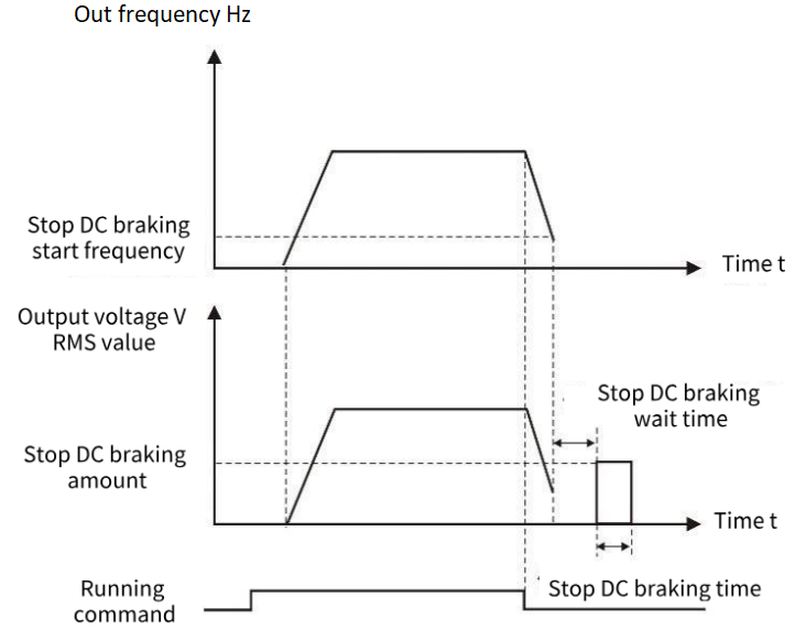
Figure 9-1-1 Shutdown DC braking diagram
| F1.16 | Energy consumption brake action voltage | Factory default | Model-based setting |
| Setting range | 115.0% to 140.0% | ||
Set the brake resistance operating voltage. When the relative value of the bus voltage is higher than this value, the brake resistance starts braking.
| F1.17 | Magnetic flux braking gain | Factory default | 80% |
| Setting range | 10% to 500% | ||
| F1.18 | Magnetic flux braking operating voltage | Factory default | Model-based setting |
| Setting range | 110% to 150% | ||
| F1.19 | Flux brake limiting | Factory default | 20% |
| Setting range | 0 to 200% | ||
When the motor decelerates the feedback energy, opening the flux brake can consume the feedback energy on the motor, so as to achieve rapid deceleration of the motor. This function is only effective in asynchronous motor VF control, and turning on this function will correspondingly increase motor loss and motor temperature rise.
Magnetic flux braking gain: The strength of magnetic flux braking, the greater the parameter, the greater the magnetic flux braking current.
Magnetic flux braking action voltage: When the relative value of the bus voltage is higher than this value, magnetic flux braking begins to work.
Flux brake limiting: The upper limit of the flux brake voltage, which may cause the output current of the inverter to be too high.
| F1.20 | Acceleration and deceleration selection | Factory default | 0 |
| Setting range | 0: Straight line 1: S curve | ||
0: Straight line, generally suitable for general purpose load.
1: S-curve, S-type acceleration and deceleration curve is mainly provided for the load that needs to slow down noise and vibration during acceleration and deceleration, reduce start-stop impact, or decrease torque at low frequency, and short-time acceleration at high frequency. If an over current or over load failure occurs at startup, reduce the set value of [F1.21].
| F1.21 | S-curve initial acceleration rate | Factory default | 50.0% |
| Setting range | 20.0% to 100.0% | ||
| F1.22 | S-curve initial deceleration rate | Factory default | 50.0% |
| Setting range | 20.0% to 100.0% | ||
S-curve Initial acceleration rate: The rate at which the acceleration process begins to increase in frequency. The smaller the initial acceleration rate, the more curved the S-curve of the acceleration process, whereas the larger the initial acceleration rate, the closer the acceleration S-curve to a straight line. To make the acceleration curve softer, you can reduce the initial acceleration rate and extend the acceleration time.
| F1.23 | Zero speed holding torque | Factory default | 0 |
| Setting range | 0.0% to 150.0% | ||
Set the output torque of the inverter at zero speed. If the torque setting is large or the duration is long, attention should be paid to the heat dissipation of the motor.
| F1.24 | Zero speed holding torque time | Factory default | Model setting |
| Setting range | 0.0 to 6000.0s If the value is set to 6000.0s, the value remains unchanged without time limitation | ||
Set the torque holding time when the inverter is running at zero speed. The timing starts when the operating frequency is 0Hz, and the inverter stops output after the time reaches the set zero-speed holding torque time. Among them, the effective timing value is 0 to 5999.9s, and the parameters are set in the effective timing value of the VFD at the set time. After the time is full, the VFD terminates and maintains the zero-speed torque.
If the parameter setting is equal to 6000.0s, the VFD is not timed and defaults to long-term validity, and the zero-speed torque holding is terminated only after the stop command is given or the non-zero operating frequency is given.
Setting an appropriate zero-speed holding torque time can effectively achieve energy saving and protect the motor.
| F1.25 | Start pre-excitation time | Factory default | 0.20 |
| Setting range | 0.00 to 60.00s | ||
This parameter is only valid if F0.00=0, in the open loop vector start, appropriate pre-excitation can make the start smoother.
| F1.26 | Shutdown frequency | Factory default | 0.00Hz |
| Setting range | 0.00 to 60.00Hz | ||
This function is defined as the frequency of the minimum output of the inverter, less than this frequency, the output of the inverter stops.
| F1.27 | Power failure restart action selection | Factory default | 0 |
| Setting range | 0: Invalid 1: Valid | ||
0: Invalid VFD power after power failure must receive the operation instruction before running.
1: Valid If the inverter is in operation before the power is cut off, the inverter will automatically start after the power is restored and after the set waiting time (set by [F1.28]). During the waiting time of power failure and restart, the inverter does not accept the running command, but if the stop command is entered during this period, the inverter will release the restart state.
| F1.28 | Power failure restart waiting time | Factory default | 0.50s |
| Setting range | 0.00 to 120.00s | ||
When [F1.27] setting is effective, After the inverter power supply, it will wait for the time set in [F1.28] to start running.
| F1.29 | Select the terminal running protection | Factory default | 11 |
| Setting range | LED units digital: Select the terminal run instruction when powering on. 0: The terminal running instruction is invalid during power-on. 1: Terminal running instructions are valid during power-on. LED tens place: Run instruction given channel switch terminal run instruction selection. 0: The terminal running instruction is invalid. 1: The terminal instruction is valid when the terminal is cut in. | ||
When terminal operation is selected, the initial wiring state of peripheral devices may affect the safety of the device. This parameter provides protective measures for terminal operation.
LED units place: Select the terminal run command when powering on
Select the mode of executing the operation instruction when the inverter is powered on with the terminal running signal in effect.
0: The terminal instruction is invalid during power-on. The terminal control stops before the power is started.
1: When the terminal is powered on, the terminal control instruction is valid.
LED tens place: Terminal run instruction selection when switching to terminal instruction from other instruction channels
Select the mode of running the instruction channel to switch to the terminal instruction mode and execute the running instruction when the terminal running signal is valid.
0: The terminal running instruction is invalid when cutting in. The terminal control stops before starting.
1: When the terminal instruction is effective, the terminal control can be started directly.
F2 group motor parameters
| F2.00 | Motor type | Factory default | 0 |
| Setting range | 0: Asynchronous motor (AM) 1: Permanent magnet synchronous motor (PM) 2: Single-phase asynchronous motors (Only VF control is supported) | ||
2 Single-phase asynchronous motor refers to a single-phase motor without phase shift capacitance, U terminal is connected to the main winding, V terminal is connected to the common end, and W terminal is connected to the auxiliary winding.
| F2.01 | Rated power of motor | Factory default | Model determination | ||||
| Setting range | 0.1kW to 400.0kW | ||||||
| F2.02 | Rated voltage of motor | Factory default | Model determination | ||||
| Setting range | 1V to 440V | ||||||
| F2.03 | Rated current of motor | Factory default | Model determination | ||||
| Setting range | 0.1A to 2000.0A | ||||||
| F2.04 | Rated power of motor | Factory default | Model determination | ||||
| Setting range | 0.00Hz to Maximum frequency F0.10 | ||||||
| F2.05 | Rated motor speed | Factory default | Model determination | ||||
| Setting range | 1rpm to 65000rpm | ||||||
| ✎Note: 1. Please set according to the nameplate parameters of the motor. 2. The excellent control performance of vector control requires accurate motor parameters, and accurate parameter identification comes from the correct setting of the rated parameters of the motor. 3. In order to ensure the control performance, please configure the motor according to the inverter standard adaptation motor, if the motor power and the standard adaptation motor gap is too large, the control performance of the inverter will be significantly reduced. | |||||||
| F2.06 | Motor stator resistance | Factory default | Model determination | ||||
| Setting range | 0.001Ω to 65.000Ω | ||||||
| F2.07 | Motor rotor resistance | Factory default | Model determination | ||||
| Setting range | 0.001Ω to 65.000Ω | ||||||
| F2.08 | Motor fixed rotor inductance | Factory default | Model determination | ||||
| Setting range | 0.1 to 6500.0mH | ||||||
| F2.09 | Mutual inductance of motor fixed rotor | Factory default | Model determination | ||||
| Setting range | 0.1 to 6500.0mH | ||||||
| F2.10 | Motor no-load current | Factory default | Model determination | ||||
| Setting range | 0.1 to 650.0A | ||||||
After the automatic tuning of the asynchronous motor is completed normally, the set values of the asynchronous motor parameters (F2.06 to F2.10) are automatically updated.
After changing the motor rated power F2.01 each time, the VFD F2.06 to F2.10 parameter values will automatically restore the default standard motor parameters, if running in vector mode, please re-tune.
| F2.11 | Tuning selection | Factory default | 0 |
| Setting range | 0: No operation is performed 1: Static tuning 1 2: Full tuning 3: Static tuning 2 (AM calculated Lm) | ||
Tip: Before tuning, you must set the correct motor type and rating parameters (F2.00 to F2.05).
0: No operation is performed, that is, tuning is disabled.
1: Static tuning 1, suitable for the motor and the load is not easy to come off and can not be rotated tuning occasions, static tuning learning asynchronous motor F2.05-F2.10 or synchronous motor F2.22 to F2.25 parameters, wherein synchronous motor back potential is calculated according to F2.01 and F2.03, if the motor power or current and the actual difference is large, Calculations may not be accurate.
Action description: Set the function code to 1, and press the RUN key to confirm, the inverter will perform static tuning.
2: Complete tuning, in order to ensure the dynamic control performance of the inverter, please select rotary tuning, rotary tuning motor must be disconnected from the load (no-load). After selecting rotary tuning, the inverter first performs static tuning, and after static tuning, the motor accelerates to 80% of the rated frequency of the motor, and maintains it for a period of time, and then decelerates and stops, and the rotary tuning ends.
Action description: Set the function code to 2, and press the RUN key to confirm, the inverter will perform rotation tuning.
3: Static tuning 2, different from static tuning 1, the tuning needs to manually input the asynchronous motor no-load current F2.10, the program will calculate the mutual inductance F2.09 according to the current, the other is the same as static tuning 1.
Action description: Set the function code to 3, and press the RUN key to confirm, the inverter will perform static tuning.
Note: Tuning can only be effective in keyboard control mode, acceleration and deceleration time is recommended to use the factory default.
| F2.12 | G/P Machine type | Factory default | Model determination |
| Setting range | 0: G-type machine; 1: P-type machine | ||
This parameter can only be used to view factory models.
1: Constant torque load for specified rated parameters.
2: Suitable for the specified rated parameters of the variable torque load (fan, pump load).
| F2.13 | Single phase asynchronous motor turns ratio | Factory default | 100% |
| Setting range | 10 to 200% | ||
U terminal main winding, V terminal auxiliary winding, W common end, this parameter is used to set the ratio of the number of turns between the main winding and the auxiliary winding of the single-phase motor.
| F2.14 | Current calibration coefficient of single-phase motor | Factory default | 120% |
| Setting range | 50 to 200% | ||
The single-phase motor has main and auxiliary windings, and the three-phase output current is unbalanced, so the output current displayed by the inverter needs to be multiplied by the coefficient of the resultant current.
| F2.15 | Number of motor poles | Factory default | 4 |
| Setting range | 2 to 48 | ||
Change F2.04 or F2.05, the program will automatically calculate the number of motor poles, in general, do not need to set this parameter.
| F2.22 | Stator resistance of synchro | Factory default | Model determination |
| Setting range | 0.001 to 65.000(0.001Ohm) | ||
| F2.23 | Synchro d-axis inductance | Factory default | Model determination |
| Setting range | 0.01mH to 655.35mH | ||
| F2.24 | Synchro Q-axis inductance | Factory default | Model determination |
| Setting range | 0.01mH to 655.35mH | ||
| F2.25 | Synchro back electromotive force | Factory default | Model determination |
| Setting range | 0.1V to 1000.0V | ||
After the automatic tuning of the synchronous motor is completed, the set values of the synchronous motor parameters (F2.22 to F2.25) are automatically updated.
After changing the rated motor power F2.01 each time, the F2.22 to F2.25 parameter values of the inverter will automatically restore the default standard motor parameters, please re-tune.
| F2.28 | High frequency injection voltage | Factory default | 20.0% |
| Setting range | 0.1% to 100.0% | ||
The current injected when the synchronous motor learns the inductance of DQ axis by high frequency injection.
| F2.29 | Back potential identification current | Factory default | 50.0% |
| Setting range | 0.1% to 100.0% | ||
The output current of the inverter is the size when the synchronous motor dynamically adjusts to learn the back potential.
| F2.31 | Asynchronous no-load current per unit value | Factory default | Model determination |
| Setting range | 0.1% | ||
| F2.32 | Per unit asynchronous stator resistance | Factory default | Model determination |
| Setting range | 0.01% | ||
| F2.33 | Asynchronous rotor resistance per unit value | Factory default | Model determination |
| Setting range | 0.01% | ||
| F2.34 | Asynchronous mutual inductance per unit value | Factory default | Model determination |
| Setting range | 0.1% | ||
| F2.35 | Asynchronous leakage sensing per unit value | Factory default | Model determination |
| Setting range | 0.01% | ||
| F2.36 | Per unit value of asynchronous leakage sensing coefficient | Factory default | Model determination |
| Setting range | 0.01% | ||
| F2.37 | Synchronous stator resistance per unit value | Factory default | Model determination |
| Setting range | 0.01% | ||
| F2.38 | Per unit value of synchronous D-axis inductance | Factory default | Model determination |
| Setting range | 0.01% | ||
| F2.39 | Synchronous Q-axis inductance per unit value | Factory default | Model determination |
| Setting range | 0.01% | ||
| F2.40 | Back electromotive force of synchronous motor | Factory default | Model determination |
| Setting range | 0.1V | ||
The per unit value of the motor parameters is used for the actual program calculation. After learning or parameter recovery, the actual change is F2.31 to F2.40. F2.06 to F2.10 and F2.22 to F2.25 are calculated from the per unit value, so only F2.31 to F2.40 values can be modified, F2.06 to F2.10 and F2.22 to F2.25 are only used to display and cannot be changed.
F3 vector control parameters
The F3 group function code is only valid in vector control mode, that is, it is valid when F0.00 = 0 and invalid when F0.00 = 1.
| F3.00 | ASR (Speed loop) proportional gain 1 | Factory default | 0.20 |
| Setting range | 0.00 to 1.00 | ||
| F3.01 | ASR(Velocity ring) integration time 1 | Factory default | 0.20 |
| Setting range | 0.01 to 10.00s | ||
| F3.03 | ASR filtering time 1 | Factory default | 0.000s |
| Setting range | 0.000 to 0.100s | ||
| F3.04 | ASR switching frequency 1 | Factory default | 5.00Hz |
| Setting range | 0.00 to 50.00Hz | ||
| F3.05 | ASR(Speed loop) proportional gain 2 | Factory default | 0.20 |
| Setting range | 0.00 to 1.00 | ||
| F3.06 | ASR(Velocity loop) integration time 2 | Factory default | 0.20 |
| 0.01 to 10.00s | |||
| F3.08 | ASR filtering time 2 | Factory default | 0.000s |
| Setting range | 0.000 to 0.100s | ||
| F3.09 | ASR switching frequency 2 | Factory default | 10.00Hz |
| Setting range | 0.00 to 50.00Hz | ||
F3.00 and F3.01 are PI adjustment parameters when the operating frequency is less than switching frequency 1 (F3.04).
F3.05 and F3.06 are PI adjustment parameters whose operating frequency is greater than switching frequency 2 (F3.09).
The PI parameters of the frequency segment between switching frequency 1 and switching frequency 2 are linear switching of the two groups of PI parameters, as shown in the figure below:
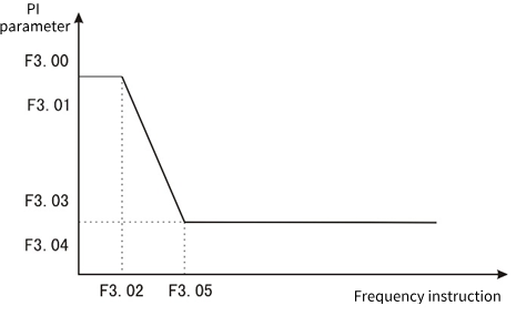
Figure 9-3-1 PI parameter diagram
The speed dynamic response characteristic of vector control can be adjusted by setting the proportional coefficient and integration time of the speed regulator. Proportional increase
If the integration time is reduced, the dynamic response of the speed loop can be accelerated. The system may oscillate if the proportional gain is too large or the integration time is too small.
Recommended adjustment method:
If the Factory parameters cannot meet the requirements, fine-tune the Factory default parameters: first increase the proportional gain to ensure that the system does not oscillate; Then the integration time is reduced so that the system has both faster response characteristics and smaller overshoot.
Note: Setting the PI parameter incorrectly may result in excessive speed overshoot. Even overvoltage failure occurs when overshoot falls back.
| F3.02 | Loss of velocity protection value | Factory default | 0ms |
| Setting range | 0 to 5000ms | ||
In order to prevent motor speed, when the motor speed is detected to have a large deviation from the target speed and maintain F3.02 time or more, the inverter alarms.
| F3.03 | ASR Filtering time 1 | Factory default | 0.000s |
| Setting range | 0.000 to 0.100s | ||
| F3.08 | ASR Filtering time 2 | Factory default | 0.000s |
| Setting range | 0.000 to 0.100s | ||
It is used to set the filtering time of the speed loop feedback. When the output frequency is below F3.04, the filtering time is F3.03. When the value is higher than F3.04, the filtering time is F3.08.
| F3.10 | Slip compensation coefficient | Factory default | 100% |
| Setting range | 0 to 250% | ||
This parameter is used to adjust the slip frequency compensation for high performance vector control. When fast response and high speed accuracy are required, proper adjustment of this parameter can improve the dynamic response speed of the system and eliminate the steady-state speed error.
| F3.11 | Maximum electric torque | Factory default | 160.0% |
| Setting range | 0.0 to 250.0% | ||
| F3.12 | Maximum generating torque | Factory default | 160.0% |
| Setting range | 0.0 to 250.0% | ||
When speed control is set, the maximum electric torque in the electric state and the maximum electric torque in the generation state are respectively.
| F3.16 | Current loop D axis proportional gain | Factory default | 1.0 |
| Setting range | 0.1 to 10.0 | ||
| F3.17 | Current loop D axis integral gain | Factory default | 1.0 |
| Setting range | 0.1 to 10.0 | ||
| F3.18 | Current loop Q axis proportional gain | Factory default | 1.0 |
| Setting range | 0.1 to 10.0 | ||
| F3.19 | Current loop Q axis integral gain | Factory default | 1.0 |
| Setting range | 0.1 to 10.0 | ||
Set PI parameter of current loop in vector control of asynchronous machine and synchronous machine. When the vector control, if the speed, current oscillation, instability phenomenon, can be appropriately reduced each gain to achieve stability; At the same time, increasing each gain helps to improve the dynamic response of the motor.
| F3.20 | D-axis feed forward gain | Factory default | 50.0% |
| Setting range | 0.0 to 200.0% | ||
| F3.21 | Q-axis feed forward gain | Factory default | 50.0% |
| Setting range | 0.0 to 200.0% | ||
The current loop has been decoupled, and the feed forward can accelerate the response speed of the current loop. Increasing feed forward can make the response faster, but it is generally not recommended to exceed 100.0%.
| F3.22 | Optimize the current loop bandwidth | Factory default | 2.00ms |
| Setting range | 0.0 to 99.99ms | ||
| F3.23 | Current loop control word | Factory default | 0 |
| Setting range | 0 to 65535 | ||
This parameter is used to set the current ring.
| F3.24 | Weak magnetic control current upper limit | Factory default | 50% |
| Setting range | 0 to 200% | ||
| F3.25 | Weak magnetic control feed forward gain | Factory default | 0% |
| Setting range | 0 to 500% | ||
| F3.26 | Weak magnetic control proportional gain | Factory default | 500 |
| Setting range | 0 to 9999 | ||
| F3.27 | Weak magnetic control integral gain | Factory default | 1000 |
| Setting range | 0 to 9999 | ||
When the asynchronous motor and permanent magnet synchronous motor work in vector mode, the weak magnetic acceleration can be carried out. F3.24 sets the upper limit of demagnetization current, and the weak magnetic function is turned off when the time phase is set to 0. F3.25 to F3.27 Set the parameters of magnetic weakening control. When instability occurs during magnetic weakening, adjust the parameters for debugging.
| F3.28 | MTPA gain | Factory default | 0.0% |
| Setting range | 0 to 500.0% | ||
| F3.29 | MTPA filtering time | Factory default | 100ms |
| Setting range | 0 to 999.9ms | ||
MTPA function is to optimize the excitation strategy of permanent magnet synchronous motor to maximize motor output/motor current; When the difference between D and Q axis inductance of permanent magnet motor is large, adjusting [F3.28] can obviously change the motor current under the same load. Adjustment [F3.29] can improve the stability of motor operation.
| F3.30 | Magnetic flux compensation coefficient | Factory default | 100% |
| Setting range | 0 to 500% | ||
| F3.31 | Open-loop vector observer gain | Factory default | 1024 |
| Setting range | 0 to 9999 | ||
| F3.32 | Open loop vector observation filtering time | Factory default | 20ms |
| Setting range | 1 to 100ms | ||
| F3.33 | The open-loop vector compensates the starting frequency | Factory default | 1.0% |
| Setting range | 0 to 100.0% | ||
| F3.34 | Open loop vector control word | Factory default | 4 |
| Setting range | 0 to 9999 | ||
This parameter is used to set the parameter of flux observation when asynchronous motor or synchronous motor is controlled by open loop vector.
| F3.35 | Synchronous open loop start mode | Factory default | 1 |
| Setting range | 0: Direct startup 1: Start at an Angle | ||
It is used to set the starting mode when the synchronous motor is open loop vector, 0 starts DC first, pulls the permanent magnet to the set position and then starts; 1 Find the permanent magnet position before starting.
| F3.36 | DC pull in time | Factory default | 500ms |
| Setting range | 1ms to 9999ms | ||
Synchronous motor start DC pull in time, time is too short may appear permanent magnet has not completely pulled to the set position on the end of the possibility, may appear not smooth start or even start failure.
| F3.37 | Synchronous open loop vector low frequency boost | Factory default | 20.0% |
| Setting range | 0 to 100.0% | ||
| F3.38 | Synchronous open loop vector high frequency boost | Factory default | 0.0% |
| Setting range | 0.0 to 100.0% | ||
| F3.39 | Low frequency boost to maintain frequency | Factory default | 10.0% |
| Setting range | 0.0 to 100.0% | ||
| F3.40 | Low frequency increases cutoff frequency | Factory default | 20.0% |
| Setting range | 0.0 to 100.0% | ||
At low frequency, the D-axis current can be appropriately increased to improve the accuracy of flux observation and starting torque. When the relative frequency (relative to the rated frequency) is lower than F3.39, the D-axis current feed is set to F3.37; When the relative frequency is higher than F3.38, the given current of D-axis is F3.38. When the relative frequency is before F3.38 and F3.39, the D-axis current is given between F3.39 and F3.40. When the synchronous motor is running at high frequency under no-load or light load (relative frequency is higher than F3.40), the D-axis current F3.38 can be set appropriately to reduce the current jitters.
| F3.46 | Speed/torque control mode | Factory default | 0 |
| Setting range | 0: Speed control 1: Torque control | ||
1: Torque control is only effective when the open loop vector is controlled, and VF control is invalid.
| F3.47 | Torque given channel selection | Factory default | 0 |
| Setting range | 0: F3.48 is set. 1: AI1╳F3.48 2: AI2╳F3.48 3: AI3╳F3.48 4: PUL╳F3.48 5: Keyboard potentiometer ╳F3.48 6: RS485 communication ╳F3.48 | ||
Torque setting adopts relative value, 100.0% corresponds to the rated torque of the motor. The Setting range is 0% to 200.0%, indicating that the maximum torque of the inverter is 2 times the rated torque of the inverter.
0: Keyboard number given by function code F3.48.
1: AI1 × F3.48 Set by AI1 terminal voltage analog input.
2: AI2 × F3.48 Set by AI2 terminal voltage or current analog input.
3: AI3 × F3.48 is set by the AI3 terminal current input analog.
4: PUL × F3.48 is set by the high-speed pulse input from the PUL terminal.
5: Keyboard potentiometer set × F7.01 by the keyboard potentiometer analog setting.
6: RS485 communication set x F3.48 is set by RS485 serial port communication.
Note: If the value of 1 to 6 is 100%, it corresponds to the value set by the function code F3.48.
| F3.48 | Torque keyboard numeric setting | Factory default | 100.0% |
| Setting range | 0 to 200.0% | ||
When the function code F3.47 = 0, the torque is set by the function code F3.48.
| F3.49 | Torque direction selection | Factory default | 00 |
| Setting range | Units: torque direction setting 0: The torque direction is positive 1: The torque direction is negative Tens place: Torque reversing setting 0: Torque reversal is allowed 1: Torque reversal is prohibited | ||
LED units place: Torque direction setting
0: The torque direction is positive inverter running.
1: The torque direction is negative inverter reversal operation.
LED tens place: Torque reversing setting
0: Allows the torque converter to keep running in one direction.
1: The torque reversal inverter can be run in both positive and negative directions.
Note: The running direction will not be affected by the F0.16 setting during torque control, and only one direction will be maintained when starting with the keyboard FWD or REV keys.
| F3.50 | Upper limit of output torque | Factory default | 150.0% |
| Setting range | F3.51 to 200.0% | ||
| F3.51 | Lower limit of output torque | Factory default | 0% |
| Setting range | 0 to F3.50 | ||
Output torque upper limit: Used to set the output torque upper limit for torque control.
Lower output torque limit: Used to set the lower output torque limit during torque control.
| F3.52 | Torque control forward speed limit selection | Factory default | 0.10s |
| Setting range | 0: F3.54 is set 1: AI1╳F3.54 2: AI2╳F3.54 3: AI3╳F3.54 4: PUL╳F3.54 5: Keyboard potentiometer given ╳F3.54 6: RS485 communication given ╳F3.54 | ||
It is used to set the maximum forward operating frequency limit of the inverter under the torque control mode.
When the converter torque control, if the load torque is less than the motor output torque, the motor speed will continue to rise, in order to prevent mechanical system accidents such as racing, it is necessary to limit the maximum motor speed during torque control.
0: Keyboard number given by function code F3.54.
1: AI1 × F3.54 Set by AI1 terminal voltage analog input.
2: AI2 × F3.54 Set by AI2 terminal voltage analog input.
3: AI3 × F3.54 is set by the AI3 terminal current input analog.
4: PUL × F3.54 is set by the high-speed pulse input from the PUL terminal.
5: Keyboard potentiometer set × F3.54 by the keyboard potentiometer analog setting.
6: RS485 communication Set × F3.54 is set by RS485 serial port communication.
✎Note: If 100% is set in 1 to 6 above, it corresponds to the value set in function code [F3.54].
| F3.53 | Torque control reversal speed limit selection | Factory default | 0 |
| Setting range | 0: F3.55 is set 1: AI1╳F3.55 2: AI2╳F3.55 3: AI3╳F3.55 4: PUL╳F3.55 5: Keyboard potentiometer given ╳F3.55 6: RS485 communication given ╳F3.55 7: Purchase card | ||
F3.53 is set the same as F3.52, F3.53 is used to limit the speed when reversing, and the corresponding number is given the function code F3.55.
| F3.54 | Torque control positive maximum speed limit | Factory default | 50.00Hz |
| Setting range | 0.00 to Upper limit frequency | ||
| F3.55 | Torque control reversal maximum speed limit | Factory default | 50.00Hz |
| Setting range | 0.00 to Upper limit frequency | ||
When function codes F3.52 and F3.53 are set to 0, the maximum speed limit is set by F3.54 and F3.55.
| F3.56 | Speed/torque switching delay | Factory default | 0.01s |
| Setting range | 0.00 to 10.00s | ||
When the speed/torque mode is switched through terminals DI1 to DI4 or F3.46, the switch can be performed only after the delay time set in F3.56.
| F3.57 | Torque acceleration time | Factory default | 0.01s |
| Setting range | 0.00 to 10.00s | ||
| F3.58 | Torque deceleration time | Factory default | 0.01s |
| Setting range | 0.00 to 10.00s | ||
In the torque operation mode, the difference between the output torque of the motor and the load torque determines the speed change rate of the motor and the load. Therefore, electricity
The speed of the machine may change rapidly, causing problems such as noise or mechanical overshoot; By setting the torque to control the acceleration and deceleration time, the motor speed can be gently changed. The torque acceleration and deceleration time is based on 2 times the rated torque of the inverter (200%).
| F3.59 | Forward and reverse torque dead zone time | Factory default | 0.00s |
| Setting range | 0.00 to 650.00s | ||
Used for the transition time waiting at 0.0Hz when the direction changes in torque operating mode.
F4 group V/F control parameters
This set of function codes is only valid for V/F control (F0.00 = 1), not for vector control.
V/F control is suitable for general-purpose loads such as fans and pumps, or for applications where a VFD has multiple motors, or where the VFD power is one or more levels less than the motor power.
| F4.00 | V/F curve and mode setting | Factory default | 0 |
| Setting range | 0: linear V/F curve; 1: Multi-point V/F curve 2: Square V/F curve 3 to 11: 1.1 to 1.9 power VF curves, respectively; 12: V/F fully separated mode | ||
Fan pump load, you can choose square V/F control.
Common VF control mode:
0: straight line V/F curve. Suitable for ordinary constant torque loads.
1: Multi-point V/F curve. Suitable for special loads such as dehydrators and centrifuges.
2: Square V/F curve. Suitable for centrifugal loads such as fans and pumps.
VF separation control mode:
12: VF complete separation mode. In this case, the output voltage is set separately according to the setting mode of F4.43(VF separated voltage source).
| F4.01 | Manual torque lift | Factory default | Model determination |
| Setting range | 0.1 to 30.0%, 0 Automatic torque boost | ||
| F4.02 | Torque boost cutoff frequency | Factory default | 50.00Hz |
| Setting range | 0.00Hz to Maximum frequency F0.10 | ||
In order to compensate the low frequency torque characteristics of V/F control, the output voltage of the inverter is improved.
The torque lift setting is too large, the motor is easy to overheat, and the inverter is easy to over current. Generally, the torque increase should not exceed 8.0%. The effective adjustment of this parameter can effectively avoid the over-current situation when starting. You are advised to increase this parameter for a large load. You can reduce this parameter when the load is light. When the torque boost is set to 0.0, the inverter is used for automatic torque boost. Torque boost torque cutoff frequency: Below this frequency, torque boost torque is effective, beyond this set frequency, torque boost failure, see Figure 9-4-1 for details.
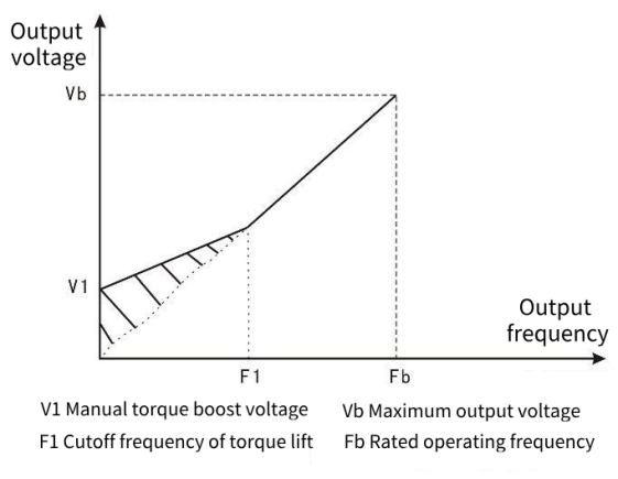
Figure 9-4-1 Manual torque raising diagram
| F4.03 | Self-set frequency F1 | Factory default | 3.00Hz |
| Setting range | 0.00Hz to F4.05 | ||
| F4.04 | Self-set voltage point V1 | Factory default | 10.0% |
| Setting range | 0.0% to 100.0% | ||
| F4.05 | Self-set frequency point F2 | Factory default | 5.00Hz |
| Setting range | F4.03 to F4.07 | ||
| F4.06 | Self-set voltage point V2 | Factory default | 15.0% |
| Setting range | 0.0% to 100.0% | ||
| F4.07 | Self-set frequency F3 | Factory default | 8.00Hz |
| Setting range | F4.05 to F4.09 | ||
| F4.08 | Self-set voltage point V3 | Factory default | 22.0% |
| Setting range | 0.0% to 100.0% | ||
| F4.09 | Self-set frequency F4 | Factory default | 12.00Hz |
| Setting range | F4.07 to Rated frequency of motorF2.04 | ||
| F4.10 | Self-set voltage point V4 | Factory default | 31.0% |
| Setting range | 0.0% to 100.0% | ||
F4.03 to F4.08 Six parameters define a multi-segment V/F curve. The setting value of the V/F curve is usually set according to the load characteristics of the motor. Note: V1 < V2 < V3 < V4, F1 < F2 < F3 < F4. When the voltage is set too high at low frequency, it may cause the motor to overheat or even burn, and the inverter may over-lose speed or over-current protection.
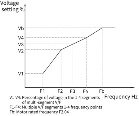
Figure 9-4-2 V/F curve setting diagram
| F4.11 | Oscillation suppression gain | Factory default | Model determination |
| Setting range | 0.0 to 10.0 | ||
| F4.12 | Oscillation suppression filtering time | Factory default | 50ms |
| Setting range | 1 to 1000ms | ||
When the motor does not oscillate, select this gain to be 0. The gain can only be properly increased when the motor obviously oscillates and cannot operate normally, and the greater the gain, the more obvious the suppression of oscillation. When the oscillation suppression function is used, the rated current and no-load current parameters of the motor are required to be set with little deviation from the actual value. The gain is selected as small as possible under the premise of effectively suppressing oscillation, so as not to have too much influence on VF operation.
| F4.14 | Percentage of output voltage | Factory default | 100% |
| Setting range | 25 to 100% | ||
The output voltage regulation coefficient of the inverter. This function is used to adjust the output voltage of the inverter to suit the needs of different V/F characteristics.
| F4.17 | EVF torque boost gain | Factory default | 100.0% |
| Setting range | 0 to 500.0% | ||
| F4.18 | EVF torque boost filtering time | Factory default | 20ms |
| Setting range | 1 to 1000ms | ||
When set to automatic torque boost F4.01=0, the torque boost works. This parameter is used to set the gain of automatic torque boost and the filtering time.
| F4.19 | EVF slip compensation gain | Factory default | 0.0% |
| Setting range | 0 to 500.0% | ||
| F4.20 | EVF slip compensation filtering time | Factory default | 100ms |
| Setting range | 1 to 1000ms | ||
This function can make the output frequency of the inverter automatically adjust in the Setting range with the change of the motor load; Dynamically compensates the slip frequency of the motor, so that the motor basically maintains a constant speed, and effectively reduces the influence of load changes on the motor speed.
| F4.21 | Automatic energy saving selection | Factory default | 50 |
| Setting range | Units place: 0 is off, 1 is on Tens place: Frequency change exit depth Hundreds place: Thousand place: | ||
| F4.22 | Lower limit frequency of energy saving operation | Factory default | 25.0% |
| Setting range | 0.0 to 100.0% | ||
| F4.23 | Energy saving and pressure reduction time | Factory default | 10.0s |
| Setting range | 0.1 to 5000.0s | ||
| F4.24 | Lower limit of energy saving and pressure reduction | Factory default | 30.0% |
| Setting range | 20.0 to 100.0% | ||
| F4.25 | Energy saving and pressure reduction rate | Factory default | 50V/s |
| Setting range | 1 to 1000V/s | ||
| F4.26 | Voltage regulated proportional gain | Factory default | 20 |
| Setting range | 0 to 100 | ||
| F4.27 | Voltage regulation integral gain | Factory default | 20 |
| Setting range | 0 to 100 | ||
Automatic energy saving options:
0: No operation
1: Automatic energy-saving operation
During operation, the inverter can automatically calculate the optimal output voltage from the load condition to save power. The power saving function is to reduce the output voltage and improve the efficiency of the motor to achieve the purpose of energy saving.
Lower limit frequency of energy-saving operation: If the output frequency of the inverter is lower than this value, even if the automatic energy-saving operation function is effective, the automatic energy-saving operation will be turned off. 100.0% corresponds to rated frequency of motor.
Energy-saving voltage reduction time: After meeting the automatic energy-saving operation conditions, the output voltage from the rated voltage of the motor to 0 volts.
Lower limit of energy-saving voltage reduction: Set the lower limit of output voltage that can be reduced during automatic energy-saving operation. 100.0% is the rated voltage of the motor.
Energy saving voltage reduction rate: The rate of voltage reduction when the output voltage is reduced during automatic energy saving operation.
Voltage regulation proportional gain: Kp parameter for automatic energy saving PI control.
Voltage regulation integral gain: Ki parameter when PI control automatically saves energy.
| F4.30 | Stabilizer proportional gain | Factory default | 10.0% |
| Setting range | 0.1% to 100.0% | ||
| F4.31 | Stabilizer filtering time | Factory default | 50ms |
| Setting range | 1ms to 1000ms | ||
Parameters of the frequency stabilizer When the synchronous motor with VVC is running. If there are unstable fluctuations in current and speed, adjusting F4.30 and F4.31 can improve and eliminate them.
| F4.32 | Low frequency current lift | Factory default | 100.0% |
| Setting range | 0.0% to 200.0% | ||
| F4.33 | Low frequency boost maintenance frequency | Factory default | 10.0% |
| Setting range | 0 to 100.0% | ||
| F4.34 | Low frequency current boosts the cutoff frequency | Factory default | 30.0% |
| Setting range | 0 to 100.0% | ||
Amplitude of the boost of the current when the synchronizer VVC is operating at low frequency. VVC has poor control of low frequency torque, so the output current will be increased at low frequency to obtain a larger starting torque. The adjustment of F4.32 can improve the motor starting torque and low-frequency carrying capacity, but the low-frequency running current increases as above.
When the frequency is lower than the maintenance frequency, the lifting current will be maintained to the F4.32 setting value. When the frequency is higher than the cut-off frequency, the lifting current drops to 0. When the frequency is between the two, the lift current boundary is between 0 and F4.32.
| F4.35 | D-axis current gain | Factory default | 2.0 |
| Setting range | 0.0 to 100.0 | ||
| F4.36 | Q-axis current gain | Factory default | 2.0 |
| Setting range | 0.0 to 100.0 | ||
When the synchronous motor with VVC is controlled, the D-axis voltage adjusts the gain.
When the synchronous motor with VVC is controlled, the Q-axis voltage adjusts the gain.
| F4.37 | Magnetic flux set strength | Factory default | 30.0% |
| Setting range | 0 to 500% | ||
| F4.38 | Magnetic flux control proportional gain | Factory default | 500 |
| Setting range | 0 to 9999 | ||
| F4.39 | Magnetic flux controls the integral gain | Factory default | 500 |
| Setting range | 0 to 9999 | ||
Synchronous motor with VVC control is a kind of control mode based on reactive power stabilization. This set of parameters is used to set the amount of reactive power, and the gain and integral of the reactive power controller.
| F4.40 | DC pull in time | Factory default | 1000ms |
| Setting range | 1ms to 9999ms | ||
When the synchronous motor with VVC is started, the permanent magnet needs to be pulled to the set position. This parameter is used to set the pulling time. During this time, the inverter outputs DC.
| F4.41 | Startup frequency | Factory default | 3.00Hz |
| Setting range | 0.00Hz to 99.00Hz | ||
| F4.42 | Startup frequency time | Factory default | 3.0s |
| Setting range | 0.0s to 999.0s | ||
To prevent VVC synchronous motor start out of step, the program control the motor to accelerate to a lower frequency for a period of time, this set of parameters is used to set the maintenance frequency and time, within the start frequency time, the motor will not accelerate.
| F4.43 | V/F Separate the output voltage source | Factory default | 0 |
| Setting range | 0: function code F4.44 setting 1: AI1 is set 2: AI2 is set 3: Reverse 4: Set the terminal PULSE 5: Multi-speed 6: Simple PLC 7: PID 8: Communication is given 100% corresponding to the rated voltage of the motor | ||
Define the voltage source for VF separation. The output voltage can come from a digital setting (F4.13), or from an analog input channel, multi-speed instruction, PLC, PID, or communication set. When the output voltage is set non-numerically, 100% of the input setting corresponds to the rated voltage of the motor, and the absolute value of the input setting is taken as the effective setting value.
0: Numeric setting (F4.44); The voltage is set directly via F4.13.
1: AI1 2: AI2 Voltage is determined by the analog input terminal, AI input 0 to 100% corresponds to the output voltage 0V to rated voltage of the motor.
4. PULSE pulse setting (DI4) The voltage is set by the terminal pulse, need to set F5.28 to F5.31 to determine the correspondence between the given signal and the given voltage (100% corresponding to the rated voltage of the motor). Pulse given signal specifications: voltage range 9V to 30V, frequency range 0kHz to 100kHz.
Pulse Settings can only be input from the high-speed pulse input terminal DI6.
- Multi-stage speed: When the voltage source is multi-stage speed, it is necessary to set the F4 group "input terminal" and the FC group "multi-stage speed and PLC" parameters to determine the correspondence between the given signal and the given voltage (100% corresponding to the rated voltage of the motor).
6. Simple PLC: When the voltage source is simple PLC, it is necessary to set the FC group "multi-speed and PLC" parameters to determine the given output voltage (100% corresponding to the rated voltage of the motor).
7. PID: Generate output voltage according to PID closed loop. For details, see FA Group PID.
8. Communication set. The voltage is set by the upper computer through communication (100% corresponding to the rated voltage of the motor).
| F4.44 | V/F separation output voltage digital setting | Factory default | 0 |
| Setting range | 0.0% to 100.0% | ||
When the voltage source is set digitally, this value is directly used as the output voltage target value.
| F4.45 | V/F separation voltage rise time | Factory default | 1.0 |
| Setting range | 0.0 to 1000.0s | ||
| F4.46 | V/F separation voltage drop time | Factory default | 1.0 |
| Setting range | 0.0 to 1000.0s | ||
VF separation rise time refers to the time required for the output voltage to change from 0V to the rated voltage of the motor. As shown in Figure 9-4-3:

Figure 9-4-3 V/F Separation diagram
| F4.47 | V/F separate stop mode | Factory default | 0 |
| Setting range | 0: The voltage/frequency simultaneously decreases to 0 1: The frequency decreases after the voltage drops to 0 | ||
This parameter sets the way VF separation stops.
F5 Input terminals
DI5 to DI8 terminal function selection (Extension) : Standard two-channel extension DI.
| F5.00 | DI1 terminal function Select | Factory default | 1 |
| F5.01 | DI2 terminal function Select | Factory default | 2 |
| F5.02 | DI3 terminal function Select | Factory default | 9 |
| F5.03 | DI4 terminal function Select | Factory default | 12 |
| F5.04 | DI5 terminal function Select(expansion) | Factory default | 0 |
| F5.05 | DI6 terminal function Select(expansion) | Factory default | 0 |
| F5.08 | AI1 selects the DI terminal function | Factory default | 0 |
| F5.09 | AI2 selects the DI terminal function | Factory default | 0 |
This parameter is used to set the corresponding function of the digital multifunction input terminal:
| Setting value | Function | Description |
|---|---|---|
| 0 | No function | The inverter does not operate even if there is a signal input. Unused terminals can be set to no function to prevent misaction. |
| 1 | Forward running (FWD) | Control the inverter forward and reverse rotation through external terminals. |
| 2 | Reverse running (REV) | |
| 3 | Three-wire operation control | Use this terminal to determine that the inverter operating mode is three-wire control mode. For details, please refer to F5.16 three-wire control mode function code introduction. |
| 4 | Forward jog (FJOG) | FJOG is a forward jog, RJOG is a reverse jog.The jog frequency, acceleration and deceleration time refer to the detailed description of F8.00, F8.01, F8.02 function code. |
| 5 | Reverse jog (RJOG) | |
| 6 | Terminal UP | Modify the frequency increment and decrement instructions when the frequency is given by the external terminal. The set frequency can be adjusted up or down when the frequency source is set to a digital setting. |
| 7 | Terminal DOWN | |
| 8 | Free parking | The AC Drive blocks the output, the motor parking process is not controlled by the inverter. A method often used for loads of large inertia and where there is no requirement for stopping time. This method has the same meaning as the free parking mentioned in F1.10. |
| 9 | Reset fault (RESET) | External fault reset function. The function is the same as RESET key on the keyboard. Remote fault reset can be realized with this function. |
| 10 | Operation pause | The inverter slows down and stops, but all operating parameters are memory state. Such as PLC parameters, pendulum parameters, PID parameters. After the signal disappears, the inverter will resume operation to the state before stopping. |
| 11 | External fault normally open input | When the external fault signal is sent to the inverter, the inverter reports a fault and stops |
| 12 | Multi-segment speed instruction terminal 1 | A total of 15 segment speeds can be set through the combination of the digital state of the four terminals. The detailed composition is shown in Table 1. |
| 13 | Multi-segment speed instruction terminal 2 | |
| 14 | Multi-segment speed instruction terminal 3 | |
| 15 | Multi-segment speed instruction terminal 4 | |
| 16 | Acceleration and deceleration time selection 1 | Selects four acceleration and deceleration times through the combination of the digital states of the two terminals. The detailed composition is shown in Schedule 2. |
| 17 | Acceleration and deceleration time selection 2 | |
| 18 | Frequency source Switching | When the frequency source selection (F0.07 bits) is set to 2, this terminal is not the primary frequency source X, otherwise it is the secondary frequency source Y. When the frequency source selection (F0.07 bits) is set to 3, this terminal is invalid as the primary frequency source X, otherwise it is the result of the primary and secondary operations. |
| 19 | UP/DOWN setting Clear | When the frequency is set to digital frequency, this terminal can clear the frequency value of UP/DOWN change, so that the given frequency is restored to the value set by F0.08. |
| 20 | Run the instruction to switch terminals | When the command source (F0.01=1) is set to terminal control, the terminal is switched to keyboard control. When the command source (F0.01=2) is set to Communication control, this terminal is switched to keyboard control. |
| 21 | Acceleration and deceleration Disable | Ensure that the inverter is not affected by external signals (except for shutdown commands) and maintain the current output frequency. |
| 22 | PID pause | PID temporarily fails, inverter maintains current frequency output. |
| 23 | PLC state reset | The PLC is paused during execution, and can be returned to the initial state of the simple PLC through this terminal when running again. |
| 29 | Torque control disable | The torque control mode of the inverter is prohibited. 30 PULSE Pulse input |
| 30 | PULSE pulse input (valid for DI4 only) | Is the pulse input terminal. |
| 32 | Immediate DC braking | The terminal is effective, the inverter directly switches to DC braking state, and exits if invalid. |
| 33 | External fault normally closed input | |
| 35 | PID action direction Take the reverse terminal | If this terminal is valid, the PID action direction is opposite to the direction set in F9.03. |
| 36 | External parking terminal 1 (Panel only) | For keyboard control, the terminal can be used to STOP, which is equivalent to the Stop key on the keyboard. |
| 37 | Control command switch terminal | This terminal is valid. If F0.01 is set to terminal control, it switches to communication control. If F0.01 is set to communication control, switch to terminal control. |
| 38 | PID Integration pause terminal | If the terminal is valid, the PID integration function is paused, but the proportional and differential adjustment still work. |
| 39 | Primary frequency source and Preset frequency switching terminal | If this terminal is valid, replace the primary frequency source with the preset frequency (F0.08). |
| 40 | Auxiliary frequency source and Preset frequency switching terminal | If this terminal is valid, replace the auxiliary frequency source with the preset frequency (F0.08). |
| 43 | PID parameter switching | This terminal is valid only when the terminal F9.18(PID parameter switching condition) is the DI terminal. Parameter F9.15 to F9.17 is used for PID. The terminal is invalid. Parameters F9.05 to F9.07 are used. |
| 44 | User-defined fault 1 | When the external fault signal is sent to the VFD, the VFD reports a fault and stops. |
| 45 | User-defined fault 2 | When the external fault signal is sent to the VFD, the VFD reports a fault and stops. |
| 46 | Speed control/torque control switching | Switch the inverter to run in torque control or speed control mode. If this terminal is invalid, it runs in the mode defined by F3.09 (speed/torque control mode), and if it is valid, it switches to the other mode. |
| 47 | Emergency stop | This terminal is valid and the inverter stops at F8.09 emergency stop time. |
| 48 | External parking terminal 2 | In any control mode, this terminal can be used to stop the car, according to the deceleration time 4. |
| 49 | Deceleration DC braking | This terminal is effective, the inverter first decelerates to the shutdown DC braking starting frequency and then switches to the DC braking state, and exits when invalid. |
| 50 | Clear the current running time | If this terminal is valid, the inverter's current running timing time will be cleared, and this function will be used for timing running (F8.42). |
Schedule 1: multi-stage speed function description.
| K4 | K3 | K2 | K1 | Frequency setting | Corresponding parameter |
|---|---|---|---|---|---|
| OFF | OFF | OFF | OFF | Multiple speed 0 | FD.0 |
| OFF | OFF | OFF | ON | Multiple speed 1 | FD.01 |
| OFF | OFF | ON | OFF | Multiple speed 2 | FD.02 |
| OFF | OFF | ON | ON | Multiple speed 3 | FD.03 |
| OFF | ON | OFF | OFF | Multiple speed 4 | FD.04 |
| OFF | ON | OFF | ON | Multiple speed 5 | FD.05 |
| OFF | ON | ON | OFF | Multiple speed 6 | FD.06 |
| OFF | ON | ON | ON | Multiple speed 7 | FD.07 |
| ON | OFF | OFF | OFF | Multiple speed 8 | FD.08 |
| ON | OFF | OFF | ON | Multiple speed 9 | FD.09 |
| ON | OFF | ON | OFF | Multiple speed 10 | FD.10 |
| ON | OFF | ON | ON | Multiple speed 11 | FD.11 |
| ON | ON | OFF | OFF | Multiple speed 12 | FD.12 |
| ON | ON | OFF | ON | Multiple speed 13 | FD.13 |
| ON | ON | ON | OFF | Multiple speed 14 | FD.14 |
| ON | ON | ON | ON | Multiple speed 15 | FD.15 |
Schedule 2: Acceleration and deceleration time selection instructions.
| Terminal 2 | Terminal 1 | Acceleration or deceleration time selection | Corresponding parameter |
|---|---|---|---|
| OFF | OFF | Acceleration time 1 | F0.17 , F0.18 |
| OFF | ON | Acceleration time 2 | F8.03 , F8.04 |
| ON | OFF | Acceleration time 3 | F8.05 , F8.06 |
| ON | ON | Acceleration time 4 | F8.07 , F8.08 |
| F5.10 | AI1 input selection | Factory default | 0 |
| Setting range | 0: 0 to 10V 1: 4 to 20mA 2: 0 to 20mA 3: 0 to 5V 4: 0.5 to 4.5V | ||
| F5.11 | AI2 input selection | Factory default | 1 |
| Setting range | 0: 0 to 10V 1: 4 to 20mA 2: 0 to 20mA 3: 0 to 5V 4: 0.5 to 4.5V | ||
AI1 input selection: AI1 does not support current input.
| F5.12 | VDI1 terminal function selection | Factory default | 0 |
| F5.13 | VDI2 terminal function selection | Factory default | 0 |
| F5.14 | VDI3 terminal function selection | Factory default | 0 |
VDI1 to VDI3 terminal function: Three virtual DI.
| F5.15 | DI filtering time | Factory default | 0.010s |
| Setting range | 0.000s to 1.000s | ||
Set the sensitivity of the DI terminal. If the digital input terminal is susceptible to interference and cause misoperation, this parameter can be increased, the anti-interference ability is enhanced, but the sensitivity of the DI terminal is reduced.
| F5.16 | Terminal command mode | Factory default | 0 |
| Setting range | 0: Two-line type 1 1: Two-wire type 2 2: Three-wire type 1 3: Three-wire type 2 | ||
This parameter defines four different ways to control the operation of the inverter through the external terminals.
0: Two-wire mode 1: This mode is the most commonly used two-wire mode. The FWD and REV terminal commands determine the forward and reverse of the motor. (active level)
1: Two-wire mode 2: FWD is the enabled terminal in this mode. The direction is determined by the state of REV. (active level)
2: Three-wire control mode 1: Din is the enable terminal in this mode, and the direction is respectively controlled by FWD and REV (pulse effective). This is done by disconnecting the Din terminal signal when stopping.
3: Three-wire control mode 2: The enable terminal of this mode is Din, the running command is given by FWD (pulse effective), and the direction is determined by the state of REV. The stop command is done by disconnecting Din's signal.
Din is the multifunctional input of DI1 to DI4, and its corresponding terminal function should be defined as function No. 3 "three-wire operation control".
| F5.17 | UP/DOWN Rate of change | Factory default | 0.50Hz |
| Setting range | 0.01Hz to 655.35Hz | ||
Press the UP/DOWN button and the terminal to adjust the change rate of the set frequency.
| F5.18 | AI1 minimum input | Factory default | 0.00V |
| Setting range | 0.00V to F5.20 | ||
| F5.19 | AI1 the minimum input corresponds to the setting | Factory default | 0% |
| Setting range | -100.00% to +100.0% | ||
| F5.20 | AI1 maximum input | Factory default | 10.00V |
| Setting range | F5.18- +10.00V | ||
| F5.21 | AI1 the maximum input corresponds to the setting | Factory default | 100.0% |
| Setting range | -100.00% to +100.0% | ||
| F5.22 | AI1 filtering time | Factory default | 0.10s |
| Setting range | 0.00s-10.00s | ||
| F5.23 | AI2 minimum input | Factory default | 2.00V |
| Setting range | -10.00V to F5.25 | ||
| F5.24 | AI2 the minimum input corresponds to the setting | Factory default | 0% |
| Setting range | -100.00% to +100.0% | ||
| F5.25 | AI2 maximum input | Factory default | 10.00V |
| Setting range | F5.23 to +10.00V | ||
| F5.26 | AI2 the maximum input corresponds to the setting | Factory default | 100.0% |
| Setting range | -100.00% to +100.0% | ||
| F5.27 | AI2 filtering time | Factory default | 0.10s |
| Setting range | 0.00s to 10.00s | ||
The above function code defines the relationship between the analog input voltage and the set value represented by the analog input. When the analog input voltage exceeds the set maximum input range, the other part will be calculated as the maximum input; when the analog input voltage exceeds the set minimum input range, the other part will be calculated according to the AI minimum input. When the analog input is a current input, 1mA current is equivalent to 0.5V voltage. In different applications, the nominal value corresponding to the simulated 100% is different, please refer to the description of each application.
The following illustrations illustrate several settings:

Figure 9-5-1 simulates the correspondence between given and set quantities
| F5.28 | PULSE input minimum frequency | Factory default | 0.00kHz |
| Setting range | 0.00 to F5.30 | ||
| F5.29 | PULSE the minimum frequency corresponds to the setting | Factory default | 0% |
| Setting range | -100.00% to +100.0% | ||
| F5.30 | pulse input maximum frequency | Factory default | 20.00kHz |
| Setting range | F5.28 to 50.00kHz | ||
| F5.31 | PULSE maximum frequency Correspondence setting | Factory default | 100.0% |
| Setting range | -100.00% to +100.0% | ||
| F5.32 | PULSE filtering time | Factory default | 0.10s |
| Setting range | 0.00s to 10.00s | ||
This set of function codes defines the correspondence when pulses are used as the frequency setting mode. Pulse frequency input can only be entered through the DI4 channel. The application of this set of functions is similar to that of AI1.
| F5.33 | DI1 enable the delay time | Factory default | 0.0s |
| Setting range | 0.0s to 360.0s | ||
| F5.34 | DI2 enable the delay time | Factory default | 0.0s |
| Setting range | 0.0s to 360.0s | ||
| F5.35 | DI1 forbidden energy delay time | Factory default | 0.0s |
| Setting range | 0.0s to 360.0s | ||
| F5.36 | DI2 forbidden energy delay time | Factory default | 0.0s |
| Setting range | 0.0s to 360.0s | ||
Set the delay time between the DI terminal state change and the VFD response.
At present, only DI1\DI2 has the ability to set the delay time.
| F5.37 | Enter terminal valid status setting 1 | Factory default | 0 |
| Setting range | 0: The low level is valid 1: The high level is valid LED units place: D1 terminal LED tens place: D2 terminal LED hundreds place: D3 terminal LED thousands place: D4 terminal | ||
| F5.38 | Enter terminal valid status setting 2 | Factory default | 0 |
| Setting range | 0: The low level is valid 1: The high level is valid LED units place: D5 terminal (Extended) LED tens place: D6 terminal (Extended) | ||
| F5.39 | Enter terminal valid status setting 3 | Factory default | 0 |
| Setting range | 0: The low level is valid 1: The high level is valid LED units place: AI1 LED tens place: AI2 LED Hundreds place: AI3 (Extended) | ||
| F5.40 | Analog input curve selection | Factory default | 0 |
| Setting range | The ones place: AI1 Tens place: AI2 Hundreds place: AI3 (Extended) 0: Straight line (default) 1: Curve 1 2: Curve 2 | ||
Defines a valid state setting for the input terminal.
High: The connection between the DI terminal and COM is valid, but the disconnect is invalid.
Low level: The connection between the DI terminal and COM is invalid, and the disconnect is valid.
| F5.57 | AI3(Extension) is used to select the DI terminal function | Factory default | |
| Setting range | For details, see the function table of the DI multi-function input terminal | ||
| F5.58 | AI4(Extension) is used to select the DI terminal function | Factory default | |
| Setting range | For details, see the function table of the DI multi-function input terminal | ||
| F5.59 | AI3(Extension) input selection | Factory default | 0 |
| Setting range | 0: 0 to 10V 1: 4 to 20mA 2: 0 to 20mA 3: 0 to 5V 4: 0.5 to 4.5V | ||
| F5.60 | AI3(Extension) input selection | Factory default | 0 |
| Setting range | 0: 0 to 10V 1: 4 to 20mA 2: 0 to 20mA 3: 0 to 5V 4: 0.5 to 4.5V | ||
| F5.61 | AI3(Extended) lower limit | Factory default | -10.00V |
| Setting range | 0 to F5.63 | ||
| F5.62 | AI3(Extended) lower limit is set accordingly | Factory default | -100.00% |
| Setting range | -100.0% to +100.0% | ||
| F5.63 | AI3(Extended) Upper limit | Factory default | 10.00V |
| Setting range | F5.61 to +10.00V | ||
| F5.64 | The AI3(Extended) upper limit corresponds to the setting | Factory default | 100.00% |
| Setting range | -100.0% to +100.0% | ||
2-channel expansion AI.
| F5.65 | AI3(Extended) filtering time | Factory default | 0.10s |
| Setting range | 0.00 to 10.00s | ||
The above function code defines the relationship between the analog input voltage and the set value represented by the analog input. When the analog input voltage exceeds the set maximum input range, the other part will be calculated as the maximum input; when the analog input voltage exceeds the set minimum input range, the other part will be calculated according to the AI minimum input. When the analog input is a current input, 1mA current is equivalent to 0.5V voltage. In different applications, the nominal value corresponding to the simulated 100% is different, please refer to the description of each application.
The following illustrations illustrate several settings:
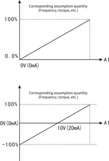
Figure 9-5-1 Simulates the correspondence between given and set quantities
F6 group output terminals
The VC series VFD standard unit has 2 multi-function relay output terminals, 1 FM terminal (which can be used as a high-speed pulse output terminal or as an open collector output), and 2 multi-function analog output terminals.
| F6.00 | FM Terminal output selection | Factory default | 1 | |
| Setting range | 0 | Pulse output | ||
| 1 | Open collector output (FMR) | |||
FM terminals are programmable multiplexed terminals. Can be used as a high speed pulse output terminal (FMP), pulse frequency up to 100kHz. Refer to F6.06 for FMP related functions. Also available as an open collector output terminal (FMR). See F6.01 for FMR functions.
FMP function needs hardware support.
| F6.01 | FMR Open collector output selection | Factory default | 0 |
| F6.02 | Relay 1 output selection | Factory default | 2 |
| F6.03 | Relay 2 output selection (Extended) | Factory default | 0 |
| F6.06 | VDO1 output selection | Factory default | 0 |
| F6.07 | VDO2 output selection | Factory default | 0 |
| F6.08 | VDO3 output selection | Factory default | 0 |
Multi-function output terminal function selection are as follows:
| Setting value | Function | Description |
|---|---|---|
| 0 | No-output | The output terminal has no function |
| 1 | VFD in operation | Indicates that the inverter is running, there is an output frequency (can be zero) at this time output ON signal. |
| 2 | Fault output | When the inverter fails and fails to stop, the output ON signal. |
| 3 | Frequency level detects FDT arrival | Please refer to function codes F8.19 and F8.20 for detailed instructions |
| 4 | Frequency arrival | Please refer to function code F8.26 for detailed instructions. |
| 5 | Running at zero speed | The VFD operates and the output frequency is 0, and the output signal is ON. |
| 6 | Motor overload pre-alarm | Before the motor electronic thermal protection action, according to the overload forecast value, after exceeding the forecast value output ON signal. Motor overload parameters are set in FA.00 to FA.02. |
| 7 | Inverter overload pre-alarm | After checking the inverter overload, 10s before the protection occurs. Output ON signal. |
| 8 | Set count pulse value to arrive | When the count value reaches the value set by FB.08, the ON signal is output. |
| 9 | Specified count pulse value arrived | When the count value reaches the value set by FB.09, the ON signal is output. For the counting function, see FB group function description |
| 10 | Length reached | When the actual length of the detection exceeds the length set by FB.05, the ON signal is output. |
| 11 | PLC cycle complete | When the simple PLC completes a cycle, it outputs a pulse signal with a width of 250ms. |
| 12 | Cumulative running time arrived | When the accumulated running time of the inverter exceeds the time set by F8.17, the output ON signal. |
| 13 | - | - |
| 14 | Torque limit | When the torque limit function is operated, the stall protection function automatically acts, automatically changes the output frequency, and the output ON signal indicates that the output torque is limited. This output signal can be used to reduce the load or to display an overload status signal on the monitoring device. |
| 15 | Operational readiness | The main circuit and control circuit power supply are established, the inverter protection function is not active, and the inverter is in the running state, the ON signal is output. |
| 16 | AI1>AI2 | When the value of the analog input AI1 is greater than that of the other input AI2, the ON signal is output. |
| 17 | Frequency upper limit reached | Output ON signal when the operating frequency reaches the upper limit frequency. |
| 18 | Frequency lower limit reached (Run related) | Output ON signal when the operating frequency reaches the lower limit frequency. In the shutdown state, the signal is always OFF. |
| 19 | Undervoltage state output | The inverter outputs ON signal when it is undervoltage. |
| 20 | Communication setting | See related instructions in the communication protocol |
| 21 | Positioning completed | Reserve |
| 22 | Positioning close | Reserve |
| 23 | Zero speed running 2 (Also output when shut down) | VFD output frequency is 0, output ON signal (shutdown also output). |
| 24 | Accumulative power-on time reached | When F7.13(the accumulated power-on time of the inverter) exceeds the time set by F8.16, the ON signal is output. |
| 25 | Frequency level detection FDT2 output | For details, see function codes F8.28 and F8.29. |
| 26 | Frequency to 1 output | For details, see function codes F8.30 and F8.31. |
| 27 | Frequency to 2output | For details, see function codes F8.32 and F8.33. |
| 28 | Current reaches 1 output | For details, see function codes F8.38 and F8.39. |
| 29 | Current reaches 2 output | For details, see function codes F8.40 and F8.41. |
| 30 | Timed arrival output | When F8.42(timing function selection) is effective, the VFD will output ON signal when the running time reaches the set timing time. |
| 31 | - | - |
| 32 | - | |
| 33 | Running direction | When the inverter runs in reverse, the ON signal is output |
| 34 | - | |
| 35 | Module temperature reach | |
| 36 | Software overcurrent output | For details, see function codes F8.36 and F8.37. |
| 37 | Lower limit frequency reached (Run independent) | Output ON signal when the operating frequency reaches the lower limit frequency. (When the conditions are met, the ON signal will also be output in the shutdown state) |
| 38 | Fault output (Continue running) | When the inverter fails, output ON signal |
| 39 | Reserve | |
| 40 | The running time arrive | |
| 41 | User defined output 1 | User can define the conditions to output the terminal |
| 42 | User-defined output 2 | User can define the conditions to output the terminal |
| 43 | Timer output | Output ON signal when the timing setting condition is met |
| 44 | Forward running status | If the inverter is in forward running, output ON signal |
| 45 | Reverse running status | If the inverter is in reverse running, output ON signal |
| F6.10 | AO output signal selection | Factory default | 00 |
| Setting range | The ones place: AO1 0: 0 to 10V 1: 4.00 to 20.00mA 2: 0.00 to 20.00mA Tens place: AO2 (Extended) 0: 0 to 10V 1: 4.00 to 20.00mA 2: 0.00 to 20.00mA | ||
All models 1 AO.
| F6.11 | FMP (Pulse output terminal) output selection | Factory default | 0 |
| Setting range | 0: Running frequency 1: Set the frequency 2: Output current 3: Output torque 4: Output power 5: Output voltage 6: Reserve 7: AI1 8: AI2 9: AI3 10: PULSE input value 11: Reserve 12: Communication settings 13: Motor speed 14: Output current (0-1000A, corresponding to 0-10V) 15: Output voltage (0-1000V, corresponding to 0-10V) 16: Bus voltage (0-1000V, corresponding to 0-10V) | ||
| F6.12 | AO1 output selection | Factory default | 0 |
| Setting range | Consistent with F6.11 setting range | ||
| F6.13 | AO2 output selection (Extended) | Factory default | 0 |
| Setting range | Consistent with F6.11 setting range | ||
The standard output of the analog output (zero bias is 0, gain 1) is 0mA to 20mA (or 0V to 10V).
The range of corresponding quantities represented is shown in the following table:
| Setting value | Function | Range |
|---|---|---|
| 0 | Operating frequency | 0 to Maximum output frequency |
| 1 | Setting frequency | 0 to Maximum output frequency |
| 2 | Output current | 0 to 2 times the rated motor current |
| 3 | Output torque | 0 to 2 times the rated motor torque |
| 4 | Output power | 0 to 2 times rated power |
| 5 | Output voltage | 0 to 1.2 times rated voltage of inverter |
| 6 | Reserve | |
| 7 | AI1 | 0V to10V |
| 8 | AI2 | 0V to 10V/0-20mA |
| 9 | Reserve | |
| 10 | Length | 0 to Maximum set length |
| 11 | Count value | 0 to Maximum count value |
| 12 | Communication setting | -10000 to 10000 |
| 13 | Motor speed | 0 to The maximum output frequency corresponds to the speed |
| 14 | Output current | 0 to 1000A, correspondence 0 to 10V 0 to 1000V, correspondence 0 to 10V |
| 15 | Output voltage | 0.0V to 1000.0V |
| 16 | Bus voltage | 0 to 1000V, correspondence 0 to 10V |
| F6.14 | FM upper frequency output limit | Factory default | 20.00kHz |
| Setting range | 0.00 to 100.00kHz | ||
F6.00 maximum frequency of pulse output when selecting pulse output.
| F6.15 | AO1 minimum input | Factory default | 0.00V |
| Setting range | 0.00V to F6.17 | ||
| F6.16 | AO1 the minimum input corresponds to the setting | Factory default | 0.0% |
| Setting range | 0.0% to +100.0% | ||
| F6.17 | AO1 maximum input | Factory default | 10.00V |
| Setting range | F6.15 to +10.00V | ||
| F6.18 | AO1 the maximum input corresponds to the setting | Factory default | 100.0% |
| Setting range | 0.0% to +100.0% | ||
The above function code defines the relationship between the analog output voltage and the set value represented by the analog output. When the analog output voltage exceeds the set maximum output range, the other part will be calculated as the maximum output; when the analog output voltage exceeds the set minimum output range, the other part will be calculated according to the AO minimum output. When the analog output is a current output, 1mA current is equivalent to 0.5V voltage. In different applications, the nominal value corresponding to the simulated 100% is different, please refer to the description of each application.
| F6.19 | AO2 minimum input (Extended) | Factory default | 0.00V | |
| Setting range | 0.00V to F6.21 | |||
| F6.20 | AO2 minimum Input mapping Settings (Extended) | Factory default | 0.0% | |
| Setting range | 0.0% to +100.0% | |||
| F6.21 | AO2 maximum input (Extended) | Factory default | 10.00V | |
| Setting range | F6.19 to +10.00V | |||
| F6.22 | AO2 maximum input corresponding Settings (Extended) | Factory default | 100.0% | |
| Setting range | 0.0% to +100.0% | |||
| F6.23 | FMR turn-on delay time | Factory default | 0.0s | |
| Setting range | 0.0s to 3600.0s | |||
The above function code defines the relationship between the analog output voltage and the set value represented by the analog output. When the analog output voltage exceeds the set maximum output range, the other part will be calculated as the maximum output; when the analog output voltage exceeds the set minimum output range, the other part will be calculated according to the AO minimum output. When the analog output is a current output, 1mA current is equivalent to 0.5V voltage. In different applications, the nominal value corresponding to the simulated 100% is different, please refer to the description of each application.
| F6.24 | Relay 1 on delay time | Factory default | 0.0s |
| Setting range | 0.0s to 3600.0s | ||
| F6.25 | Relay 2 turn-on delay time (Extended) | Factory default | 0.0s |
| Setting range | 0.0s to 3600.0s | ||
| F6.26 | VDO connection delay | Factory default | 0.0s |
| Setting range | 0.0s to 3600.0s | ||
| F6.27 | FMR disconnect delay time | Factory default | 0.0s |
| Setting range | 0.0s to 3600.0s | ||
| F6.28 | Relay 1 disconnect delay time | Factory default | 0.0s |
| Setting range | 0.0s to 3600.0s | ||
| F6.29 | Relay 2 disconnect delay time (Extended) | Factory default | 0.0s |
| Setting range | 0.0s to 3600.0s | ||
| F6.30 | VDO1 disconnect delay | Factory default | 0.0s |
| Setting range | 0.0s to 3600.0s | ||
Set the delay time of output terminals FMR, relay 1, relay 2, VDO from the change of state to the change of output.
| F6.31 | Output terminal valid status Select 1 | Factory default | 000 |
| Setting range | 0: Positive logic 1: Reverse logic Units place: FDOR Tens place: RL1 Hundreds place: RL2 (Extended) Thousands place: - | ||
| F6.32 | Virtual output terminal valid status Select 2 | Factory default | 000 |
| Setting range | 0: Positive logic 1: Reverse logic Units place: VDO1 Tens place: VDO2 Hundreds place: VDO3 Thousands place: - | ||
Define the positive and negative logic of the output terminals FMR, relay 1, relay 2.
Positive logic: the digital output terminal and the corresponding public end are connected effectively, and the disconnect is invalid;
Inverse logic: The digital output terminal is not connected to the corresponding public end, and the disconnect is valid.
| F6.33 | User-defined output selection (EX) 1 | Factory default | 0 |
| Setting range | 0: The running frequency 1: Set the frequency 2: Bus voltage 3: Output voltage 4: Output current 5: Output power 6: Output torque 7-8: Reserved 9: AI1 input 10: AI2 input 11: AI3 input (Extended) | ||
This parameter is used to select a reference variable for the custom output. Take the selected variable EX as the operation comparison object.
| F6.34 | The comparison method chosen by the user 1 | Factory default | 0 |
| Setting range | Units: Compare test methods 0: Equal to (EX == X1) 1: The value is greater than or equal to 2: Less than or equal to 3: Interval comparison (X1 ≤ EX ≤ X2) 4: Bit test (EX & X1=X2) Tens: output mode 0: False value output 1: Truth output | ||
The units bit selects the comparison test mode. The variables selected by F6.37 are used as comparison test objects, and the comparison and test values are set by F6.40-F6.41.
The way the tens select the output. False value output is output if the condition is not met, and no output if it is met; Truth output is output only when the condition is met, and no output if the condition is not met.
| F6.35 | User-defined dead zone 1 | Factory default | 0 |
| Setting range | 0 to 65535 | ||
When the comparison test mode of F6.29 is set to greater than or equal to or less than or equal to, F6.30 is used to define the processing dead zone value centered on the comparison value X1. The processing dead zone has effect only on 1 and 2 of the comparison test mode of F6.29, and has no effect on 0, 3, and 4. For example, when F6.29 is set to 11, when EX is increased from 0 to greater than or equal to X1+F6.30, the output is valid; When EX is reduced to less than or equal to X1.F6.30, the output is invalid.
| F6.36 | User-defined 2 outputs the comparison value X1 | Factory default | 0 |
| Setting range | 0 to 65535 | ||
| F6.37 | User-defined 2 outputs the comparison value X2 | Factory default | 0 |
| Setting range | 0 to 65535 | ||
| F6.38 | User-defined output selection (EX) 2 | Factory default | 0 |
| Setting range | 0: Running frequency 1: Set the frequency 2: Bus voltage 3: Output voltage 4: Output current 5: Output power 6: Output torque 7-8: Reserved 9: AI1 input 10: AI2 input 11: AI3 input(Expansion module) | ||
These two parameters are used to set the comparison value of the custom output.
Here is an example of a custom output:
1. When the set frequency is greater than or equal to 20.00HZ, the relay is closed;
Set parameters as follows: F6.02 = 41,F6.33 = 1,F6.34 = 11,F6.35 = 0,F6.36 = 2000;
2. When the bus voltage is less than or equal to 500.0V, the relay is closed; In order to avoid frequent operation of the relay when the detection voltage fluctuates 5.0V above and below 500.0V, it is required to process into a dead zone in the range of (500.0-5.0) to (500.0+5.0).
Set parameters as follows: F6.02 = 41,F6.33 = 2,F6.34 = 01,F6.35 = 50,F6.36 = 5000;
3. When the inverter is required to reverse, the relay is closed:
Set parameters as follows: F6.02 = 41,F6.33 = 2,F6.34 = 01,F6.31 = 8,F6.37= 8;
4. When AI1 input is required to be greater than 3.00V and less than or equal to 6.00V, the relay is closed:
Set parameters as follows: F6.02 = 41,F6.33=13,F6.34=13,F6.36=300,F6.37=600
| F6.39 | The comparison method chosen by the user 2 | Factory default | 0 |
| Setting range | Units: Compare test methods 0: Equal to (EX == X1) 1: The value is greater than or equal to 2: Less than or equal to 3: Interval comparison (X1 ≤ EX ≤ X2) 4: Bit test (EX & X1=X2) Tens: output mode 0: False value output 1: Truth output | ||
| F6.40 | User-defined dead zone 2 | Factory default | 0 |
| Setting range | 0 to 65535 | ||
| F6.41 | User-defined 2 outputs the comparison value X1 | Factory default | 0 |
| Setting range | 0 to 65535 | ||
| F6.42 | User-defined 2 Output comparison value X2 | Factory default | 0 |
| Setting range | 0 to 65535 | ||
Second output. The parameter setting mode is the same as F6.33 to F6.37.
| F6.43 | Timer time unit | Factory default | 0 |
| Setting range | 0: Second 1: Minute 2: Hour | ||
| F6.44 | Timer maximum | Factory default | 0 |
| Setting range | 0 to 65535 (No more when set to 65000) | ||
| F6.45 | Timer set value | Factory default | 0 |
| Setting range | 0 to 65535 | ||
| F6.46 | Counter maximum | Factory default | 0 |
| Setting range | 0 to 65535 | ||
| F6.47 | Counter set value | Factory default | 0 |
| Setting range | 0 to 65535 | ||
Set the timer time.
F7 group keyboard with display
| F7.00 | LCD keyboard parameter copy | Factory default | 0 |
| Setting range | 0: No operation is performed 1: The function parameters of the machine are uploaded to the LCD keyboard 2: LCD keyboard function parameters download to the machine | ||
✎Note: LCD is not available.
| F7.01 | ENT key function selection | Factory default | 0 |
| Setting range | 0: ENT is invalid 1: Switch between the command channel of the operation panel and the remote command channel (the remote command channel includes communication and terminal control) 2: Forward/reverse switching 3: Forward JOG 4: Reverse JOG 5: Menu mode switch 6: Reverse operation | ||
The ENT key is multiplexed into a multi-function key on the level 0 interface. The function of ENT key on the keyboard can be defined by parameter setting. This key can be used to switch between shutdown and operation.
0: This key has no function if it is set to 0.
1: Switch between keyboard commands and remote operations. Switching from the current command source to keyboard control (local operation). If the current command source is keyboard control, this command does not take effect.
2: Forward/reverse switching
Use the ENT key on the keyboard to switch the direction of the frequency instruction. This parameter is valid only when the command channel on the panel is operated.
3: Forward JOG
The forward turning point (FJOG) is achieved by the ENT key on the keyboard.
4: Reverse JOG
Reversal dotting (RJOG) is achieved by the ENT key on the keyboard.
Note: After setting this function, it is only effective in the 0-level display menu, and ENT key is the function of entering the lower-level menu/saving parameters in other interfaces.
5: Menu mode switch
Operating instructions: base for the initial menu, -C- for the debugging menu; ENT key to switch the menu, shift key to enter the corresponding menu; debugging menu displayed as CFxx.xx
| F7.02 | Keyboard STOP key range | Factory default | 0011 |
| Setting range | LED units place: Terminal control selection 0: The terminal command is invalid 1: valid for the terminal command LED tens place: communication control selection 0: The communication command is invalid 1: Valid for communication commands LED hundreds place: reserved LED thousands place: reserved | ||
✎Note: When the STOP button communication control is valid, if the machine is started by using the communication command and the machine is stopped by using the STOP button, it can be started only after the STOP command is issued before the next communication start.
| F7.03 | Keyboard run displays parameter 1 | Factory default | 3420 |
| Setting range | LED units place: First group display 0: Output frequency 1: Given frequency 2: Bus voltage 3: Output voltage 4: Output current 5: Output power 6: Output torque 7: DI input status 8: DO output status 9: AI1 voltage A: AI2 voltage B: AI3 voltage (Expansion module) C: Reverse D: Reverse E: Motor speed F: PID setting LED tens place: Second group display LED hundreds place: Third group display LED thousands place: Fourth group display | ||
| F7.04 | Keyboard run displays parameter 2 | Factory default | 0000 |
| Setting range | LED units place: First group display 0: No displayed 1: PID feedback 2: PLC stage 3:PULSE Indicates the input pulse frequency 4: Feedback speed 5: Reservations 6: Reservations 7: Reservations 8: Reserve 9: Current power-on time A: Current running time B: Reserved C: Communication setting D: Reservation E: Main frequency X is displayed F: Auxiliary frequency Y is displayed LED ten: Second group display LED hundreds place: Third group display LED thousands place: Fourth group display | ||
| F7.05 | Keyboard stop displays parameters | Factory default | 3421 |
| Setting range | LED units place: First group display 0: Output frequency 1: Given frequency 2: Bus voltage 3: Output voltage 4: Output current 5: Output power 6: Output torque 7: DI input status 8: DO output status 9: AI1 voltage A: AI2 voltage B: AI3 voltage(Expansion module) C: Motor speed D: PID setting E: PID feedback F: PLC stage LED tens place: second group display LED hundreds place: Third group display LED thousands place: Fourth group display | ||
Control four groups of display parameters. For example, if output frequency, bus voltage, output current, and output voltage need to be displayed during operation, set the corresponding value 3420 one by one in bits to kilos.
| F7.06 | Load speed display factor | Factory default | 1.000 |
| Setting range | 0.001 to 65.000 | ||
Through this parameter, the output frequency of the inverter is corresponding to the load speed, load speed = output frequency /F2.04*F2.05*F7.06.
| F7.14 | High cumulative power consumption | Factory default | |
| Setting range | Power consumption = F7.14*65535+F7.15 Unit: kWh | ||
| F7.15 | Low cumulative power consumption | Factory default | |
| Setting range | Power consumption=F7.14*65535+F7.15 Unit: kWh | ||
When the inverter power is large, the 16-bit power consumption parameter will overflow quickly, so two parameters are used to represent the power consumption, that is, 32 digits.
| F7.16 | Output power correction factor | Factory default | 100.0% |
| Setting range | 0 to 100.0% | ||
Used to correct the actual output power of the motor.
| F7.17 | Power display dimension selection | Factory default | 1 |
| Setting range | 0 to Power display percentage (%) 1 to Power display kilowatts (kW) | ||
Used to select the dimension of power display D0.05, 0 is displayed in the ratio of output power to motor power, and 1 is displayed in KW.
F8 group accessibility
| F8.00 | JOG running frequency | Factory default | 2.00Hz |
| Setting range | 0.00Hz to Maximum frequency F0.10 | ||
| F8.01 | JOG acceleration time | Factory default | 20.0s |
| Setting range | 0.01s to 6500.0s | ||
| F8.02 | JOG deceleration time | Factory default | 20.0s |
| Setting range | 0.01s to 6500.0s | ||
Define the given frequency and acceleration/deceleration time of the inverter during jog. The jog process starts and stops according to start mode 0 (F1.00, direct start) and stop mode 0 (F1.10, decelerate to stop).
Jog acceleration time refers to the time required for the inverter to accelerate from 0Hz to the maximum output frequency (F0.10).
Jog deceleration time refers to the time required for the inverter to decelerate from the maximum output frequency (F0.10) to 0Hz..
| F8.09 | Emergency stop deceleration time | Factory default | Model determination |
| Setting range | 0. 01s to 6500.0s | ||
The terminal is set to downtime in case of emergency stop.
| F8.10 | Jump frequency 1 | Factory default | 0.00Hz |
| Setting range | 0.00Hz to Maximum frequency | ||
| F8.11 | Jump frequency 2 | Factory default | 0.00Hz |
| Setting range | 0.00 Hz to Maximum frequency | ||
| F8.12 | Jump frequency amplitude | Factory default | 0.01Hz |
| Setting range | 0.00 to Maximum frequency | ||
When the set frequency is within the jump frequency range, the actual running frequency will run at the jump frequency boundary closer to the set frequency. By setting the jump frequency, the VFD can avoid the mechanical resonance point of the load. The inverter can be configured with two jump frequency points. This function does not work if both jump frequencies are set to 0.
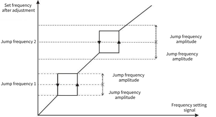
Figure 9-8-1 Jump frequency diagram
| F8.13 | Reversible dead zone time | Factory default | 0.0s |
| Setting range | 0.0 to 120.0s | ||
Set the transition time at the output zero frequency during the positive and negative transition of the inverter, as shown below:
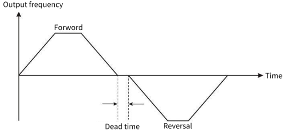
Figure 9-8-2 Reverse rotation dead zone time diagram
| F8.14 | The carrier frequency is adjusted with temperature | Factory default | 1 |
| Setting range | 0: Temperature independent 1:Temperature dependent, >75, 1.0Khz | ||
Effective carrier frequency temperature adjustment means that the VFD can automatically adjust the carrier frequency according to its own temperature. Select this function to reduce the chances of VFD overheating alarm.
| F8.15 | Terminal action is preferred | Factory default | 1 |
| Setting range | 0: Invalid 1: Valid | ||
0: When the running command and the point command exist at the same time, the running command takes precedence.
1: If the running command and the point-action command exist at the same time, the point-action command takes precedence.
| F8.16 | Set the cumulative power-on arrival time | Factory default | 0h |
| Setting range | 0h to 65000h | ||
Pre-set the power-on time of the inverter. When the cumulative power-on time (F7.13) reaches the set power-on time, set the DO output function, and the inverter multi-function digital DO output running time arrival signal.
| F8.17 | Set the cumulative run arrival time | Factory default | 65000h |
| Setting range | 0h to 65000h | ||
Pre-set the running time of the inverter. When the accumulated running time (F7.09) reaches this set running time, set the DO output function, the inverter multi-functional digital DO output running time arrival signal.
| F8.20 | Arrival time of this run | Factory default | 0 |
| Setting range | 0 to 65000min | ||
Set the current running time, shutdown clear zero.
| F8.22 | Frequency detection value (FDT1) | Factory default | 50.00Hz |
| Setting range | 0.00Hz to Maximum frequency | ||
| F8.23 | Frequency Detection Lag value (FDT1) | Factory default | 5.0% |
| Setting range | 0.0% to 100.0%(FDT1 Electric level) | ||
| F8.24 | Frequency detection value (FDT2) | Factory default | 50.00Hz |
| Setting range | 0.00Hz to Maximum frequency | ||
| F8.25 | Frequency detection lag value (FDT2) | Factory default | 5.0% |
| Setting range | 0.0% to 100.0%(FDT2 Electric level) | ||
Set the detection value of the output frequency and the lag value of the output action release.
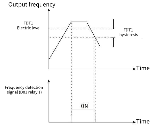
Figure 9-8-3 Schematic diagram of FDT1 level
| F8.26 | Frequency reaches the detection width | Factory default | 0.0% |
| Setting range | 0.00 to 100% Maximum frequency | ||
When the output frequency of the inverter reaches the set frequency value, this function can adjust its detection amplitude.
As shown below:
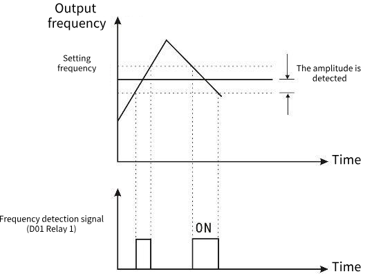
Figure 9-8-4 Schematic diagram of frequency arrival detection amplitude
| F8.27 | Arbitrary reach frequency detection value 1 | Factory default | 50.00Hz |
| Setting range | 0.00Hz to Maximum frequency | ||
| F8.28 | Arbitrary arrival frequency detection amplitude 1 | Factory default | 0.0% |
| Setting range | 0.0% to 100.0% (Maximum frequency) | ||
| F8.29 | Arbitrary reach frequency detection value 2 | Factory default | 50.00Hz |
| Setting range | 0.00Hz to Maximum frequency | ||
| F8.30 | Arbitrary arrival frequency detection amplitude 2 | Factory default | 0.0% |
| Setting range | 0.0% to 100.0% (Maximum frequency) | ||
When the output frequency of the inverter reaches the positive and negative detection amplitude of the frequency detection value 1 and 2, the output pulse signal.
As shown below:
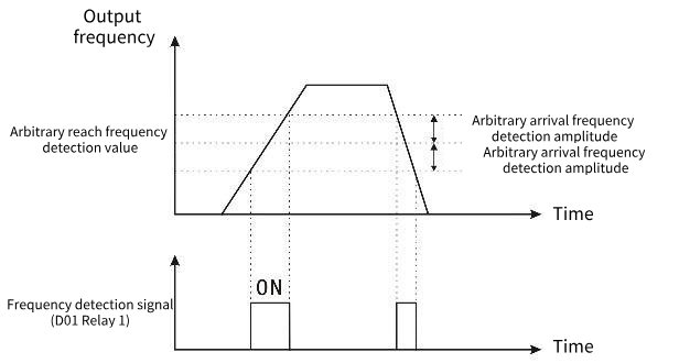
Figure 9-8-5 Schematic diagram of detection of arbitrary arrival frequency
| F8.31 | Arbitrary arrival current 1 | Factory default | 100.0% |
| Setting range | 0.0%-300.0% (Rated current of motor) | ||
| F8.32 | Arbitrary arrival current 1 width | Factory default | 0.0% |
| Setting range | 0.0%-300.0% (Rated current of motor) | ||
| F8.33 | Arbitrary arrival current 2 | Factory default | 100.0% |
| Setting range | 0.0% to 300.0%(Rated current of motor) | ||
| F8.34 | Arbitrary arrival current 2 width | Factory default | 0.0% |
| Setting range | 0.0% to 300.0%(Rated current of motor) | ||
When the output current of the inverter reaches any positive or negative detection width of current 1 and 2, output pulse signal.
As shown below:
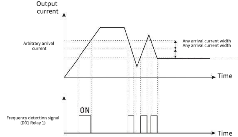
Figure. 9-8-6 Schematic diagram of detection of arbitrary arrival frequency
| F8.35 | Zero current detection value | Factory default | 5.0% |
| Setting range | 0.0% to 300.0% (Rated current of motor) | ||
| F8.36 | Zero current detection delay time | Factory default | 0s |
| Setting range | 0 to 600.00s | ||
When the output current of the inverter is less than or equal to the zero current detection level and the duration exceeds the zero current detection delay time, the output pulse
Rush the signal. As shown below:
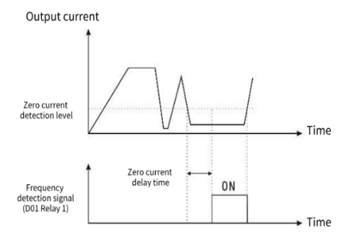
Figure 9-8-7 Schematic diagram of zero current detection
| F8.37 | Software overflow point (DO output) | Factory default | 200.0% |
| Setting range | 0.0% to 300.0% (Rated current of VFD) | ||
| F8.38 | Software over current detection delay time | Factory default | 0s |
| Setting range | 0 to 600.00s | ||
When the output current of the inverter is greater than or equal to the software over current point and the duration exceeds the software over current point detection delay time, the output pulse
Rush the signal. As shown below:
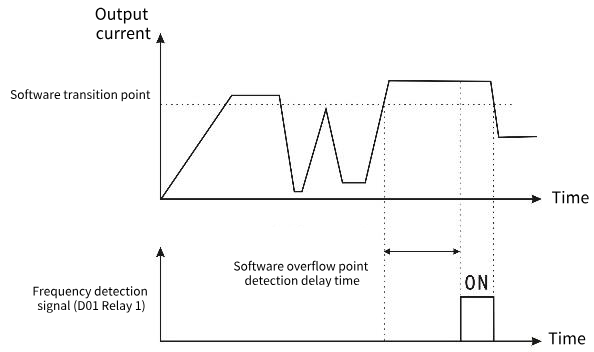
Figure 9-8-8 Schematic diagram of software overflow point detection
F9 group process control PID function
PID control is a common method used for process control. By proportional, integral and differential operations on the difference between the feedback signal of the controlled quantity and the target quantity signal, the output frequency of the inverter is adjusted to form a negative feedback system, so that the controlled quantity is stable on the target quantity. Suitable for flow control, pressure control, temperature control and other process control. The basic control block diagram is as follows:
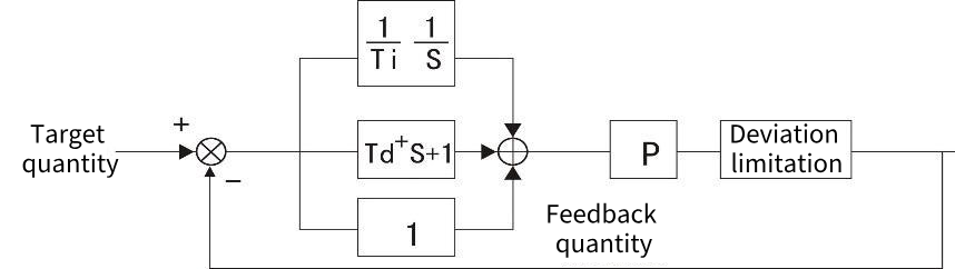
Figure 9-9-1 Process PID schematic diagram
| F9.00 | PID given source | Factory default | 0 |
| Setting range | 0: Keyboard number PID is set to F9.01 1: AI1 2: AI2 3: Reservations 4: Set the terminal PULSE 5: Communication given 6: Multi-speed set 7: Keyboard potentiometer set | ||
When the frequency source is selected PID, that is, F0.03 or F0.04 is selected 8, this set of functions works. (See function code F0.03-F0.04.) This parameter determines the target amount of the process PID for a given channel. The set target quantity of process PID is relative value, and 100% of the set value corresponds to 100% of the feedback signal of the controlled system. The range of the PID (F9.04) is not required, because the system calculates relative values (0 to 100%) regardless of the range set. However, if the PID range is set, the actual value of the PID given and feedback corresponding to the signal can be visually observed through the keyboard display parameters.
| F9.01 | PID Value setting | Factory default | 50.0% |
| Setting range | 0.00 to 100.0% | ||
When F9.00=0 is selected, the target source is the keyboard given. This parameter needs to be set. The reference value of this parameter is the feedback amount of the system.
| F9.02 | PID feedback source | Factory default | 0 |
| Setting range | 0: AI1 1: AI2 2: Reservations 3: AI1 to AI2 4: Set the terminal PULSE 5: Communication given 6: AI1+AI2 7: MAX(|AI1|, |AI2|) 8: MIN(|AI1|, |AI2|) 9: Keyboard potentiometer feedback | ||
This parameter is used to select the PID feedback channel.
| F9.03 | PID control characteristic | Factory default | 0 |
| Setting range | LED ones digit: Feedback feature selection 0: Positive action 1: Negative action LED tens place: PID adjustment direction selection 0: Reverse prohibition 1: Reverse enable LED hundreds place: Align selection 0: Non-center alignment 1: Center align LED thousands place: reserved | ||
Feedback feature selection:
Positive effect: When the feedback signal is less than the given PID, the output frequency of the inverter is required to rise in order to make the PID balance. Such as winding tension PID control.
Reverse effect: When the feedback signal is less than the feed time of the PID, the output frequency of the inverter is required to decrease in order to achieve balance of the PID. Such as unwinding tension PID control.
The effect of this function is negatively affected by the direction of the terminal function 35: PID.
Adjustment direction selection:
Reverse prohibition: When the output frequency is calculated to be negative, the inverter outputs 0 Hz.
Reverse allowed: the inverter output changes direction and the motor reverses.
Align selection:
When the PID set point is not at the center point of 50%, the difference between the PID set point and the PID feedback value, that is, the error range, is asymmetrical.
Off-center alignment: Errors are not corrected.
Center alignment: Error correction.
| F9.04 | PID given feedback range | Factory default | 100.0 |
| Setting range | 0 to 100.0 | ||
| F9.05 | Proportional gain P1 | Factory default | 20.00 |
| Setting range | 0.00 to 1000.00 | ||
| F9.06 | Integration time I1 | Factory default | 2.00s |
| Setting range | 0.00 to 10.00s | ||
| F9.07 | D1derivative time D1 | Factory default | 0.00s |
| Setting range | 0.00 to 10.00s | ||
Proportional gain P1: Determines the adjustment intensity of the entire PID regulator, the greater the P, the greater the adjustment intensity. The parameter 100 indicates that when the deviation between the PID feedback quantity and the feed quantity is 100%, the PID: regulator's adjustment amplitude to the output frequency instruction is Maximum frequency (ignoring the integral and differential effects).
Integration time I1: determines how quickly the PID controller adjusts the amount of PID feedback and the deviation of the given quantity. Integration time refers to when the deviation of PID feedback quantity and feed quantity is 100%, the integration regulator (ignoring proportional action and differential action) is continuously adjusted through the time, and the adjustment amount reaches the Maximum frequency (F0.10). The shorter the integration time, the greater the adjustment intensity.
Differential time D1: Determines the intensity with which the PID regulator adjusts the amount of PID feedback and the rate of change of the given amount of deviation. The differential time means that if the feedback quantity changes 100% in this time, the adjustment amount of the differential regulator is Maximum frequency (F0.10) (ignoring the proportional action and integral action). The longer the differential time, the greater the adjustment intensity.
| F9.08 | Reverse cut-off frequency | Factory default | 0.00Hz |
| Setting range | 0.00 to Maximum frequency F0.10 | ||
| F9.09 | PID deviation limit | Factory default | 0.0% |
| Setting range | 0. 0% to 100.0% | ||
Deviation limit: When the PID feedback deviation is within this range, the PID stops adjusting.
| F9.10 | PID differential limiting | Factory default | 0.10% |
| Setting range | 0.00% to 100.00% | ||
| F9.11 | PID given change time | Factory default | 0.00s |
| Setting range | 0.00s to 100.00s | ||
The given PID change time refers to the time required for the actual PID value to change from 0.0% to 100.0%.
When the PID set changes, the actual value of the PID set does not follow the immediate response. And according to the given change time linear change, prevent a given mutation.
| F9.12 | PID feedback filtering time | Factory default | 0.00s |
| Setting range | 0.00s to 60.00s | ||
| F9.13 | PID output filtering time | Factory default | 0.00s |
| Setting range | 0.00s to 60.00s | ||
The PID feedback and output values are filtered to eliminate abrupt changes.
| F9.14 | Proportional gain P2 | Factory default | 20.0 |
| Setting range | 0.0 to 100.0 | ||
| F9.15 | Integration time I2 | Factory default | 2.00s |
| Setting range | 0.01s to 10.00s | ||
| F9.16 | Differential time D2 | Factory default | 0.000s |
| Setting range | 0.00 to 10.000 | ||
The setting is similar to F9.05, F9.06, and F9.07. For details about how to change the PID parameters, see F9.18.
| F9.17 | PID parameter switching condition | Factory default | 0 |
| Setting range | 0: No switching 1: Terminal switch 2: Automatically switch according to deviation | ||
| F9.18 | PID parameter switching deviation 1 | Factory default | 20.0% |
| Setting range | 0.0% to F9.19 | ||
| F9.19 | PID parameter switching deviation 2 | Factory default | 80.0% |
| Setting range | F9.18 to 100.0% | ||
In some applications, a single set of PID parameters may not be sufficient for the entire operation. Multiple groups of PID parameters may need to be switched.
0: No switching, and the PID parameter is constant as parameter group 1.
1: Terminal switch, If the function of the multi-function terminal is set to 43: PID parameter switching terminal and the terminal is valid, select parameter group 2. Otherwise, select parameter group 1.
2: Automatic switching according to the deviation. When the deviation between the given and feedback is less than PID parameter switching deviation 1 (F9.19), F9.05, F9.06 and F9.07 are used as PID adjustment parameters. When the deviation between given and feedback is greater than PID switching deviation 2 (F9.20), F9.15, F9.16 and F9.17 are used as PID adjustment parameters. The PID parameters in the deviation section between switching deviation 1 and switching deviation 2 are linearly switched between the two groups of PID parameters.
| F9.20 | PID initial frequency value | Factory default | 0% |
| Setting range | 0.0% to 100.0% | ||
| F9.21 | PID initial retention time | Factory default | 0.0s |
| Setting range | 0.00s to 6500.0s | ||
During PID operation, the inverter first sets the output operation with the initial PID value (F9.20) and the duration is F9.21 (PID initial value holding time), and then starts the normal PID adjustment.
| F9.23 | Feedback wire break action selection | Factory default | 0 |
| Setting range | 0: PID continues to run and no fault is reported 1: Stop and report fault (manual reset) 2: Continue PID operation, output alarm signal 3: Run at the current frequency, output alarm signal 4: Stop and report fault (automatic reset) | ||
| F9.24 | Wire break alarm upper limit | Factory default | 100.0% |
| Setting range | F9.25 to 100.0% | ||
| F9.25 | Line break alarm lower limit | Factory default | 0.0% |
| Setting range | 0 to F9.24% | ||
| F9.26 | Feedback break detection time | Factory default | 0.0s |
| Setting range | 0.0s to 120.0s | ||
Determine whether the PID feedback is lost. If the PID feedback is lower than the disconnection alarm lower limit (F9.25) or higher than the disconnection alarm upper limit (F9.24) for a duration reaching F9.26 (feedback loss detection time), the inverter will report a fault and operate according to the F9.29 setting.
| F9.27 | PID stop operation | Factory default | 0 |
| Setting range | 0: Disable calculation on shutdown 1: Enable calculation on shutdown | ||
| F9.28 | PID function selection | Factory default | 0 |
| Setting range | 0: Normal PID 1: Sleep PID | ||
0: The inverter runs with normal PID control, and the sleep function is invalid.
1: The inverter runs with sleep PID control, and the sleep function is enabled.
| F9.29 | PID sleep threshold | Factory default | 60.0% |
| Setting range | 0.0% to 100.0% | ||
| F9.30 | PID sleep delay | Factory default | 3.0s |
| Setting range | 0.0 to 3600.0s | ||
| F9.31 | PID wake-up threshold | Factory default | 20.0% |
| Setting range | 0.0% to 100.0% | ||
| F9.32 | PID wake up delay | Factory default | 3.0s |
| Setting range | 0.0 to 3600.0s | ||
When selecting the sleep PID, if the feedback is higher than the sleep threshold set by F9.29 and the running frequency is less than or equal to the sleep frequency set by F9.33, the VFD starts the sleep timing. After the sleep delay time set by F9.30, if the feedback quantity is higher than the set quantity set by F9.29 and the running frequency is less than or equal to the sleep frequency set by F9.33, Then the PID stops running and the inverter enters sleep state. If the feedback is lower than the setting of F9.31 wake-up threshold, the VFD starts the wake-up timing. After the time set by F9.32 wake-up delay, if the feedback is still lower than the setting of F9.31 wake-up threshold, the wake-up is successful and PID control is performed. Refer to Figure 9-9-2 below to understand the above parameter relationships.
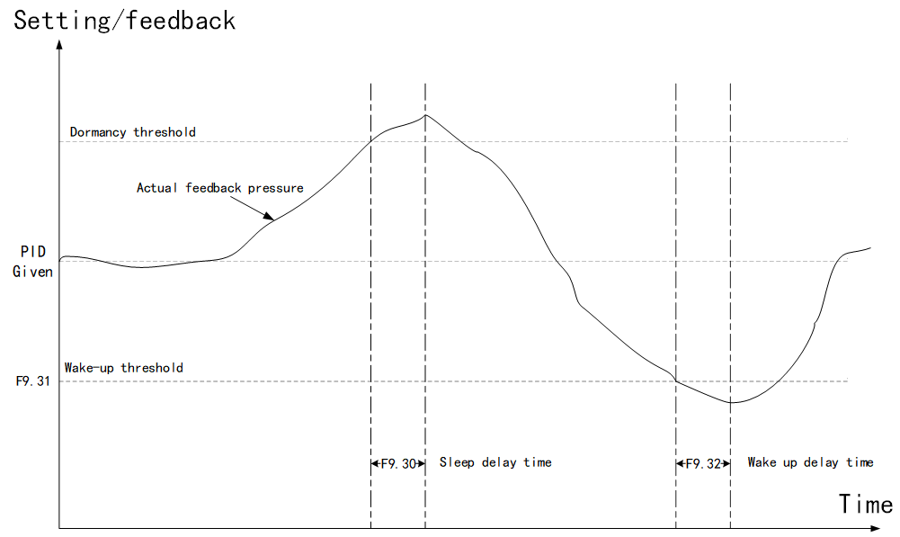
Figure 9-9-2 Schematic diagram of PID sleep and wake time sequence
| F9.33 | Dormancy detection frequency | Factory default | 25.00Hz |
| Setting range | 0 to upper limit frequency F0.12 | ||
| F9.34 | Minimum output | Factory default | 0 |
| Setting range | 0: F0.14 (Lower limit frequency) 1: 0Hz | ||
Sleep detection frequency: Frequency at which the system determines whether the sleep condition is met.
| F9.35 | Maximum forward deviation of two outputs | Factory default | 1.00%. |
| Setting range | 0.00% to 100.00% | ||
| F9.36 | Maximum reverse deviation of two outputs | Factory default | 1.00% |
| Setting range | 0.00% to 100.00% | ||
This function code is used to limit the difference between the PID output two beats (2ms/ beat), thereby suppress the PID output changes too fast. F9.23 and F9.24 correspond to the maximum output deviation for forward and reverse rotation respectively.
| F9.38 | PID preset switchover condition selection | Factory default | 0 |
| Setting range | 0: Time 1: Switch according to AI1 feedback value | ||
| F9.39 | PID AI feedback switching minimum | Factory default | 45.0% |
| Setting range | 0.0 to F8.18 | ||
| F9.40 | PID AI feedback switching maximum | Factory default | 55.0% |
| Setting range | F8.17 to 100.0% | ||
PID preset switching condition selection: Switch from preset output frequency (F9.20) to PID given.
0: Switch according to the running time set by F9.21.
1: Switch when the feedback value is greater than or equal to F9.23 and less than or equal to F9.24.
FA group failure and protection
| FA.00 | Motor overload protection selection | Factory default | 1 |
| Setting range | 0: Off 1: On | ||
Select 0: The inverter has no overload protection for the load motor, and the relay is heated in front of the motor.
Select 1: At this time, the inverter has overload protection function for the motor. See FA.01 for protection values.
| FA.01 | Motor overload protection factor | Factory default | 100.0% |
| Setting range | 0.0 to 250.0% | ||
Motor overload protection is inverse time curve; 220% x (FA.01) x rated motor current for 1 minute, 150% x (FA.01) x rated motor current for 60 minutes.
| FA.02 | Motor overload warning factor | Factory default | 80.0% |
| Setting range | 20.0 to 250.0% | ||
The reference for this value is the overload current of the motor. When the inverter detects that the output current reaches (FA.02) x the motor overload current and continues for the specified time in the inverse time curve, the forecast alarm is output from the DO or relay.
| FA.03 | Over voltage stall/over loss rate control options | Factory default | 1111 |
| Setting range | 0: Off 1: On LED units place: The over voltage suppression is enabled Tens place: over current suppression is enabled LED hundreds place: Determine whether the brake resistance is connected LED thousands place: Overflow suppression rapid frequency rise | ||
LED units place: Over voltage suppression enabled
0: Disable over voltage suppression. 1: Enable overvoltage suppression. When a braking resistor is connected, set this bit to 0.
LED tens place: Enable over current suppression
0: Disable over current suppression. 1: Enable the over current suppression function.
LED hundreds place: Determine brake resistance access
When the over voltage suppression is turned on, it may affect the energy consumption braking action. This bit is used to automatically determine whether the resistance is connected. When the brake resistance is connected, the over voltage suppression will automatically decrease.
LED thousands place: Overflow suppression rapid frequency rise
This bit is used to set how the frequency increases when over current suppression is withdrawn. When set to 0, the frequency is accelerated according to the acceleration time; When set to 1, the frequency is controlled by the current, so as the current decreases, the frequency will rise rapidly.
| FA.04 | Over pressure suppression point | Factory default | Model-based setting |
| Setting range | 110% to 150% | ||
| FA.05 | Udc control voltage loop gain | Factory default | 2.00 |
| Setting range | 0.00 to 50.00 | ||
| FA.06 | Udc control current loop gain | Factory default | 2.00 |
| Setting range | 0.00 to 50.00 | ||
When the bus voltage exceeds FA.04× rated bus voltage during the operation of the VFD, the VFD will automatically adjust the operating frequency to suppress the bus voltage rise, so as to ensure that the VFD will not cause over voltage protection due to the high bus voltage. FA.05 and FA.06 are the voltage loop gain and current loop gain when the bus voltage is regulated, respectively. Instantaneous stop of the voltage loop and current loop gain is also the reference number.
| FA.07 | Over current suppression point | Factory default | 150% |
| Setting range | 50% to 200% | ||
| FA.08 | Over current suppression gain | Factory default | 2.00 |
| Setting range | 0.00 to 50.00 | ||
| FA.09 | Over current suppression integral | Factory default | 4.00 |
| Setting range | 0.00 to 50.00 | ||
When controlling the motor, the motor current increases with the increase of load, and the over current suppression gain function limits the maximum current of the motor. When the current reaches the rated current of FA.07* inverter, the output frequency automatically decreases to limit the motor current not exceeding the current set by FA.07; FA.08 and FA.09 are over current suppression controller parameters. Adjusting these two parameters can improve and optimize the over current suppression effect.
| FA.10 | Power-on short-circuit detection to the ground | Factory default | 1 |
| Setting range | 0: Invalid 1: Valid | ||
The inverter can be selected to detect whether the motor has a ground protection short circuit fault when it is powered on. If this function is effective, the inverter is output for a short time at the moment of power-on.
| FA.11 | Input phase loss protection | Factory default | 1 |
| Setting range | 0: Off 1: On | ||
Select whether to protect against input phase loss.
| FA.12 | Output phase loss protection | Factory default | 1 |
| Setting range | 0: Off 1: On | ||
Select whether to protect output phase loss.
| FA.13 | Input phase loss protection software detection level | Factory default | 15.0% |
| Setting range | 0.0 to 999.9% | ||
The input missing phase is judged by calculating the fluctuation of bus voltage. This parameter is used to set the threshold of bus voltage fluctuation when the input phase is out. Turning down can increase the sensitive zero of the input phase out, and turning up can reduce the probability of false positive of the input phase out.
| FA.14 | PWM Parameter setting | Factory default | 0010 |
| Setting range | LED units place: Turn on voltage prediction compensation LED tens place: PWM update mode 0: Single sample update 1: Double sample and double update LED hundreds place: Random carrier mode 0: Random carrier 1: Random 0 vector | ||
LED units place: Turn on voltage prediction compensation
1: Turn on the bus voltage prediction compensation.
LED tens place: PWM update mode.
0: Single sample update. 1: Double sample and double update.
LED hundreds place: Random carrier mode.
0: Random PWM carrier frequency. 1: Random 0 vector.
| FA.15 | Hardware current and voltage protection | Factory default | 0011 |
| Setting range | LED units place: Current limiting (CBC) 0: Off 1: On LED tens place: - LED hundreds place: FAU filtering time 1 to F LED thousandsd place: TZ filtering time 1 to F | ||
LED units place: Hardware current limiting (CBC).
0: Disable CBC current limiting 1: Enable CBC current limiting
LED tens place: Reserved.
LED hundreds place: FAU filtering time.
The FAU signal is the fault signal of the power device. This parameter is used to set the filtering time of the FAU signal.
LED thousands place: TZ filtering time.
The TZ signal is an over current signal. This parameter is used to set the filtering time of the TZ signal.
| FA.16 | CBC protection point | Factory default | 200% |
| Setting range | 100 to 220% | ||
| FA.17 | CBC overload protection time | Factory default | 500ms |
| Setting range | 1 to 5000ms | ||
When the motor current is higher than the rated current of FA.16*VFD, the per-wave current limiting starts. If the per-wave current limiting duration exceeds the time set in FA.17, the VFD reports Err. This parameter is used to set the per-wave current limiting current and fault response time.
| FA.18 | Under voltage point setting | Factory default | 100.0% |
| Setting range | 40.0% to 100.0% | ||
Adjusting this parameter can adjust the voltage point of the VFD reporting the under voltage fault (Err09), 100.0% corresponds to 350V.
| FA.20 | Times of self-recovery | Factory default | 0 |
| Setting range | 0 to 5 | ||
When the inverter selects fault automatic reset, it is used to set the number of times that can be automatically reset. If the value exceeds this value, the inverter is faulty and waiting for repair.
| FA.21 | Interval for fault self-recovery | Factory default | 1.0s |
| Setting range | 0.1 to 100.0ms | ||
VFD from fault alarm to automatic reset fault waiting time.
| FA.22 | Instant stop non-stop function selection | Factory default | 0000 |
| Setting range | One place: Power loss ride-through enabled 0: Disabled 1: Enabled Tens place: Power loss ride-through selection 0: Discontinuous running 1: Stop | ||
Ones place: Power loss ride-through enabled
0: Disable power loss ride-through . 1: Enable power loss ride-through.
Tens place: Power loss ride-through selection
Select the action when the frequency drops to zero during a power loss ride-through.
0: Run at 0 Hz until under-voltage
1: Shut down immediately
| FA.23 | Power loss ride-through voltage threshold | Factory default | 75% |
| Setting range | 40% to 150% | ||
| FA.24 | Power loss ride-through stable voltage | Factory default | 95% |
| Setting range | 60% to 150% | ||
When the input power is reduced or power off, the inverter can control the motor speed down to feedback energy to avoid the VFD under voltage fault, the function is called power loss ride-through . When the bus voltage is lower than the rated bus voltage *FA.24, The power loss ride-through function is active. and control the motor to feedback energy to stabilize the bus voltage at the rated bus voltage *FA.24.
FB group swing frequency, fixed length and counting
Swing frequency function is suitable for textile, chemical fiber and other industries and need transverse movement, winding function occasions.
The function of swing frequency means that the output frequency of the inverter swings up and down with the set frequency as the center.
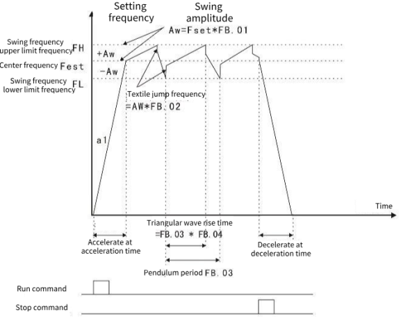
Figure 9-B-1 Schematic diagram of swing frequency operation
| FB.00 | Swing frequency control | Factory default | 0 |
| Setting range | LED ones digit: Swing frequency control 0: The swing frequency control is disable 1: Swing frequency control is effective LED tens digit: Swing frequency input mode 0: Automatic input 1: Manual input LED hundreds digit: Swing control 0: Variable amplitude 1: Fixed amplitude LED thousands digit: Reserved | ||
LED ones digit: Swing frequency control enable
LED tens digit:
0: Automatic input, according to the parameter setting, automatically enter the swing frequency run after the frequency arrives.
1: Manual input, the frequency is controlled according to the DI terminal status control
LED hundreds digit: 0: Variable amplitude, relative center frequency (set frequency), for variable amplitude system. The swing varies with the change of center frequency (set frequency).
1: Fixed amplitude, relative to maximum frequency (F0.10 maximum output frequency), it is a fixed amplitude system.
| FB.01 | Swing preset frequency | Factory default | 0.00Hz |
| Setting range | 0.00 to Maximum frequency | ||
| FB.02 | Preset frequency duration | Factory default | 0.00s |
| Setting range | 0.00 to 650.00s | ||
| FB.03 | Swing amplitude | Factory default | 0.0% |
| Setting range | 0.0% to 100.0% | ||
| FB.04 | Jump frequency amplitude | Factory default | 0.0% |
| Setting range | 0.0% to 50.0% | ||
The value of swing amplitude and jump frequency can be determined by this parameter. The operating frequency of swing frequency is constrained by the upper and lower frequency.
Swing relative to the center frequency (variable amplitude, select FB.00=0) : Swing amplitude, AW = frequency source F0.07× swing amplitude FB.01.
Swing relative to Maximum frequency (fixed amplitude, FB.00=1) : Swing amplitude, AW = Maximum frequencyF0.12 x swing amplitude FB.01.
Snap frequency = swing amplitude AW x jump frequency amplitude FB.02. That is, when the swing frequency is running, the value of the snap frequency relative to the swing amplitude.
If the swing is selected relative to the center frequency (variable swing, select FB.00=0), the jog frequency is the change value.
If the swing is selected relative to the Maximum frequency (fixed swing, select FB.00=1), the jog frequency is fixed.
| FB.05 | Swing frequency rise time | Factory default | 5.00s |
| Setting range | 0.00 to 650.00s | ||
| FB.06 | Swing frequency drop time | Factory default | 5.00s |
| Setting range | 0.00 to 650.00s | ||
Triangle wave rise time = swing frequency duration FB.02× delta wave rise time coefficient FB.05 (unit: s).
Triangle wave fall time = swing frequency duration FB.02× (1- triangle wave rise time coefficient FB.06) (unit: s).
FC Group communication parameters
| FC.00 | Local address | Factory default | 1 |
| Setting range | 1 to 247, 0 is the broadcast address | ||
When the local address is set to 0, it is the broadcast address, and the host computer broadcast function is realized. The local address is unique (except the broadcast address), which is the basis of point-to-point communication between the host computer and the inverter.
| FC.01 | Baud rate | Factory default | 5 |
| Setting range | 0: 300 bps 1: 600 bps 2: 1200 bps 3: 2400 bps 4: 4800 bps 5: 9600 bps 6: 19200 bps 7: 38400 bps 8: 57600 bps 9: 115200 bps | ||
This parameter is used to set the data transmission rate between the host computer and the VFD. Note that the baud rate set by the upper computer and the VFD must be consistent, otherwise, communication cannot be carried out. The higher the baud rate, the faster the communication speed.
| FC.02 | Modbus data format | Factory default | 3 |
| Setting range | 0: (8.N.2) 8 bits, no parity, 2 stop bits 1: (8.E.1) 8 bits, even parity, 1 stop bit 2: (8.O.1) 8 bits, odd parity, 1 stop bit 3: (8.n.1) 8 bits, no parity, 1 stop bit | ||
The data format set by the upper computer and the inverter must be consistent, otherwise, the communication cannot be carried out.
| FC.03 | Modbus Communication response delay | Factory default | 2ms |
| Setting range | 0 to 20ms | ||
Response delay: the intermediate interval between the end of the VFD data acceptance and the sending of data to the upper machine. If the response delay is less than the system processing time, the response delay is based on the system processing time. If the response delay is longer than the system processing time, the system will wait until the response delay time reaches the upper computer before sending the data.
| FC.04 | Modbus Communication timeout time | Factory default | 0.0s |
| Setting range | 0.0 s(In vain), 0.1 to 60.0s | ||
When the function code is set to 0.0s, the communication timeout parameter is invalid.
When this function code is set to valid value, if the interval between one communication and the next communication exceeds the communication timeout period, the system reports a communication fault error (Err16). Usually, this is set to invalid. If you set the next parameter in a continuous communication system, you can monitor the communication status.
FD Group multi-speed function and simple PLC function
Simple PLC function is the inverter built-in a programmable controller (PLC) to complete the automatic control of multi-segment frequency logic. Operation time, operation direction and operation frequency can be set to meet the requirements of the process. This series of inverter can realize 16 speed change control, there are 4 kinds of acceleration and deceleration time to choose. When the set PLC completes a cycle, an ON signal can be output by the multifunctional digital output terminal DO1, DO2 or the multifunctional relay relay 1, relay 2. See F1.02 to F1.05 for details. When the frequency source F0.07, F0.03, F0.04 is selected to determine the multi-speed operation mode, FD.00 to FD.15 needs to be set to determine its characteristics.
| FD.00 | Multi-segment speed instruction 0 | Factory default | 0 |
| Setting range | -100.0% to 100.0% (100.0% refers to Maximum frequency F0.10) | ||
| FD.01 | Multi-segment speed instruction 1 | Factory default | 0 |
| Setting range | -100.0% to 100.0% | ||
| FD.02 | Multi-segment speed instruction 2 | Factory default | 0 |
| Setting range | -100.0% to 100.0% | ||
| FD.03 | Multi-segment speed instruction 3 | Factory default | 0 |
| Setting range | -100.0% to 100.0% | ||
| FD.04 | Multi-segment speed instruction 4 | Factory default | 0 |
| Setting range | -100.0% to 100.0% | ||
| FD.05 | Multi-segment speed instruction 5 | Factory default | 0 |
| Setting range | -100.0% to 100.0% | ||
| FD.06 | Multi-segment speed instruction 6 | Factory default | 0 |
| Setting range | -100.0% to 100.0% | ||
| FD.07 | Multi-segment speed instruction 7 | Factory default | 0 |
| Setting range | -100.0% to 100.0% | ||
| FD.08 | Multi-segment speed instruction 8 | Factory default | 0 |
| Setting range | -100.0% to 100.0% | ||
| FD.09 | Multi-segment speed instruction 9 | Factory default | 0 |
| Setting range | -100.0% to 100.0% | ||
| FD.10 | Multi-segment speed instruction 10 | Factory default | 0 |
| Setting range | -100.0% to 100.0% | ||
| FD.11 | Multi-segment speed instruction 11 | Factory default | 0 |
| Setting range | -100.0% to 100.0% | ||
| FD.12 | Multi-segment speed instruction 12 | Factory default | 0 |
| Setting range | -100.0% to 100.0% | ||
| FD.13 | Multi-segment speed instruction 13 | Factory default | 0 |
| Setting range | -100.0% to 100.0% | ||
| FD.14 | Multi-segment speed instruction 14 | Factory default | 0 |
| Setting range | -100.0% to 100.0% | ||
| FD.15 | Multi-segment speed instruction 15 | Factory default | 0 |
| Setting range | -100.0% to 100.0% | ||
When the frequency source parameters F0.07, F0.03 and F0.04 are determined as the PLC operating mode, FD.00 to FD.15, FD.16, FD.17, FD.18 to FD.49 need to be set to determine their characteristics.
Instructions: The symbol determines the simple PLC running direction. If the value is negative, it indicates the opposite direction.
| FD.16 | PLC mode of operation | Factory default | 0 |
| Setting range | 0: Stop after a single run 1: Maintain the final value at the end of a single run 2: Keep cycling | ||
0: Stops after a single run
The inverter automatically stops after completing a single cycle and needs to give the running command again to start.
1: Maintain the final value at the end of a single run
The VFD automatically maintains the operating frequency and direction of the last section after completing a single cycle.
2: Keep cycling
After the inverter completes a cycle, it automatically starts the next cycle until the system stops when there is a stop command.
| FD.17 | PLC power down memory selection | Factory default | 00 |
| Setting range | Ones place: 0: Non-retentive on power down 1: Retentive on power down Tens place: 0: Non-retentive on shutdown 1: Retentive on shutdown | ||
Ones place: Power down retension selection
PLC power down retension: The operating stage and operating frequency of PLC before power down.
Tens place: Shutdown retention selection
PLC shutdown retention: Record the operating stage and operating frequency of the previous PLC during shutdown.
| FD.18 | PLC stage 0 operation time | Factory default | 0.0s(h) |
| Setting range | 0.0s(h) to 6553.5s(h) | ||
| FD.19 | PLC phase 0 acceleration and deceleration time selection | Factory default | 0 |
| Setting range | 0to 3 | ||
| FD.20 | PLC stage 1 operation time | Factory default | 0.0s(h) |
| Setting range | 0.0s(h) to 6553.5s(h) | ||
| FD.21 | PLC phase 1 acceleration and deceleration time selection | Factory default | 0 |
| Setting range | 0to 3 | ||
| FD.22 | PLC stage 2 operation time | Factory default | 0.0s(h) |
| Setting range | 0.0s(h) to 6553.5s(h) | ||
| FD.23 | PLC phase 2 acceleration and deceleration time selection | Factory default | 0 |
| Setting range | 0to 3 | ||
| FD.24 | PLC stage 3 operation time | Factory default | 0.0s(h) |
| Setting range | 0.0s(h) to 6553.5s(h) | ||
| FD.25 | PLC phase 3 acceleration and deceleration time selection | Factory default | 0 |
| Setting range | 0to 3 | ||
| FD.26 | PLC stage 4 operation time | Factory default | 0.0s(h) |
| Setting range | 0.0s(h) to 6553.5s(h) | ||
| FD.27 | PLC phase 4 acceleration and deceleration time selection | Factory default | 0 |
| Setting range | 0to 3 | ||
| FD.28 | PLC stage 5 operation time | Factory default | 0.0s(h) |
| Setting range | 0.0s(h)-6553.5s(h) | ||
| FD.29 | PLC phase 5 acceleration and deceleration time selection | Factory default | 0 |
| Setting range | 0to 3 | ||
| FD.30 | PLC stage 6 operation time | Factory default | 0.0s(h) |
| Setting range | 0.0s(h) to 6553.5s(h) | ||
| FD.31 | PLC phase 6 acceleration and deceleration time selection | Factory default | 0 |
| Setting range | 0to 3 | ||
| FD.32 | PLC stage 7 operation time | Factory default | 0.0s(h) |
| Setting range | 0.0s(h) to 6553.5s(h) | ||
| FD.33 | PLC phase 7 acceleration and deceleration time selection | Factory default | 0 |
| Setting range | 0to 3 | ||
| FD.34 | PLC stage 8 operation time | Factory default | 0.0s(h) |
| Setting range | 0.0s(h) to 6553.5s(h) | ||
| FD.35 | PLC phase 8 acceleration and deceleration time selection | Factory default | 0 |
| Setting range | 0to 3 | ||
| FD.36 | PLC stage 9 operation time | Factory default | 0.0s(h) |
| Setting range | 0.0s(h) to 6553.5s(h) | ||
| FD.37 | PLC phase 9 acceleration and deceleration time selection | Factory default | 0 |
| Setting range | 0 to 3 | ||
| FD.38 | PLC stage 10 operation time | Factory default | 0.0s(h) |
| Setting range | 0.0 s(h) to 6553.5s(h) | ||
| FD.39 | PLC phase 10 acceleration and deceleration time selection | Factory default | 0 |
| Setting range | 0 to 3 | ||
| FD.40 | PLC stage 11 operation time | Factory default | 0.0s(h) |
| Setting range | 0.0s(h) to 6553.5s(h) | ||
| FD.41 | PLC phase 11 acceleration and deceleration time selection | Factory default | 0 |
| Setting range | 0 to 3 | ||
| FD.42 | PLC stage 12 operation time | Factory default | 0.0s(h) |
| Setting range | 0.0s(h) to 6553.5s(h) | ||
| FD.43 | PLC phase 12 acceleration and deceleration time selection | Factory default | 0 |
| Setting range | 0 to 3 | ||
| FD.44 | PLC stage 13 operation time | Factory default | 0.0s(h) |
| Setting range | 0.0s(h) to 6553.5s(h) | ||
| FD.45 | PLC phase 13 acceleration and deceleration time selection | Factory default | 0 |
| Setting range | 0 to 3 | ||
| FD.46 | PLC stage 14 operation time | Factory default | 0.0s(h) |
| Setting range | 0.0s(h) to 6553.5s(h) | ||
| FD.47 | PLC phase 14 acceleration and deceleration time selection | Factory default | 0 |
| Setting range | 0 to 3 | ||
| FD.48 | PLC stage 15 operation time | Factory default | 0.0s(h) |
| Setting range | 0.0s(h) to 6553.5s(h) | ||
| FD.49 | PLC phase 15 acceleration and deceleration time selection | Factory default | 0 |
| Setting range | 0 to 3 | ||
| FD.50 | PLC operating time unit | Factory default | 0 |
| Setting range | LED units: Timing unit 0: s(seconds) 1: h(hours) 2: min(minutes) | ||
| FD.51 | Multi-segment speed instruction 0 given mode | Factory default | 0 |
| Setting range | 0: Function code FD.00 given 1: AI1 given 2: AI2 given 3: AI3 given 4: Set the terminal PULSE 5: PID 6: Preset frequency (F0.08) given, UP/DOWN can be modified 7: Keyboard potentiometer set | ||
This parameter determines the target amount of the multi-segment speed 0 given channel.
FD.50: PLC operating time unit.
| FD.52 | Multiple speed is preferred | Factory default | 1 |
| Set range | 0: Invalid 1: Valid | ||
Set this parameter to 1, F0.03 set the main frequency source not to multi-segment speed, and set F5 group terminal parameter multi-segment speed function,, when the terminal is valid, the frequency source switches to the multi-segment speed set, the multi-segment speed priority has nothing to do with the multi-segment speed 0.
FE Group user password
| FE.00 | User password | Factory default | 0 |
| Setting range | 0 to 65535 | ||
If the value is set to any non-zero number, the password protection function takes effect. 00000: Clears the previously set password value and invalidates the password protection function. After the user password is set and takes effect, if you enter the parameter setting state again and the user password is incorrect, the parameter group cannot be entered and cannot be viewed/modified. Remember the user password you set. If you accidentally set or forget, please contact the manufacturer.
| FE.01 | Number of times to display fault records | Factory default | 4 |
| Setting range | 0 to 8 | ||
This function code is used to set the number of times that fault records are displayed.
| FE.02 | Parameter and key lock selection | Factory default | 0 |
| Setting range | 0: Not locked 1: The function parameter is locked | ||
This function code is used to lock a parameter. After the parameter is locked, it cannot be modified.
A0 Displays the parameter group
| A0.00 | Application macro | Factory default | 0 |
| Setting range | 0: Default macro 1: Tile press macro 2: Spring mechanical macro 3: Woodworking machinery macro | ||
User macro parameter setting.