2.03 HC_COUNTER
Instruction format
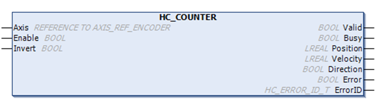
| Instruction | HC_Counter (FB) | |
| Name | Enable high speed counter | |
| Function | Use to control the start or stop of the high speed counter | |
| Graphical performance | ST performance | |
| HC_Counter( Axis: =, Enable: =, Invert =, Valid=>, Busy=>, Position=>, Velocity=>, Direction=>, Error=>, ErrorID=>); | |
| Instruction | HC_Counter (FB) | |
| Name | Enable high speed counter | |
| Function | Use to control the start or stop of the high speed counter | |
| Graphical performance | ST performance | |
 | HC_Counter( Axis: =, Enable: =, Invert =, Valid=>, Busy=>, Position=>, Velocity=>, Direction=>, Error=>, ErrorID=>); | |
Related variables
| Input variables | Name | Data type | Effective range | Initial value | Description |
| Axis | Encoder axis | AXIS_REF_ENCODER | - | - | AXIS_REF_ENCODER Encoder Axis Instance |
| Enable | Enable | BOOL | [FALSE, TRUE] | FALSE | TRUE: Enable counter |
| Invert | Count backward | BOOL | [FALSE, TRUE] | FALSE | TRUE: Change counting direction |
| Output variables | Name | Data type | Effective range | Initial value | Description |
| Valid | Enable status | BOOL | [FALSE, TRUE] | FALSE | Counter status |
| Busy | Execution flag | BOOL | [FALSE, TRUE] | FALSE | TRUE when instruction is being executed. |
| Position | Counting value | LREAL | -1.7E 308 to 1.7E 308 | 0.0 | Current count value. Calculated from the count pulse. |
| Velocity | Speed/Frequency | LREAL | -1.7E 308 to 1.7E 308 | 0.0 | Pulse frequency |
| Direction | Direction | BOOL | [FALSE, TRUE] | FALSE | Counting direction 1: forward 2: reverse |
| Error | Error flag | BOOL | [FALSE, TRUE] | FALSE | An error occurred inside the function block |
| ErrorID | Error ID | HC_ERROR_ID_T | - | HC_ERROR_ID_SUCCESS | Error ID, refer to HC_ERROR_ID_T |
Function description
Enabling the HC_COUNTER function block can count the current counter axis position, measure the current speed in real time and display the current counting direction.
The counter axis position is only set according to the current counting mode and changes within the range of the counter axis mode, and the position unit is Unit.
Note
Only if the function block Enable is TRUE, update the current axis position, speed, and counting direction;
If two function blocks are used to count at the same time in the scanning program, and the specified encoder axis parameter Axis is the same, the execution of the function block enabled first will be interrupted by the function block enabled later, and the former Busy will be set to FALSE;
After a function block execution error, the function block must be re-enabled to clear the error, otherwise the function block will not execute counting;
The counting range of the function block Position will be dynamically adjusted according to the scaling. The pulse counting value range: [-140739635838976, 140735340871679]
Invert parameter (Negative counting)
The counting direction of the counter is set by the Invert parameter. The definition of counting directions for different counting modes are shown in the following figure. When changing the Invert setting, it will take effect directly if the function block is enabled.
| Invert | Phase A/B | Pulse + Direction | CW/CCW | Single phase counting |
| FALSE | Incremental count: A phase leads B phase Decremental count: B phase leads A phase | Incremental count: Direction signal high level Decremental count: Direction signal low level | A phase incremental count. B phase Decremental count. | Incremental count |
| TRUE | Incremental count: B phase leads A phase Decremental count: A phase leads B phase | Incremental count: Direction signal low level Decremental count: Direction signal high level | B phase increment count. A phase Decremental count. | Decremental count |
Description
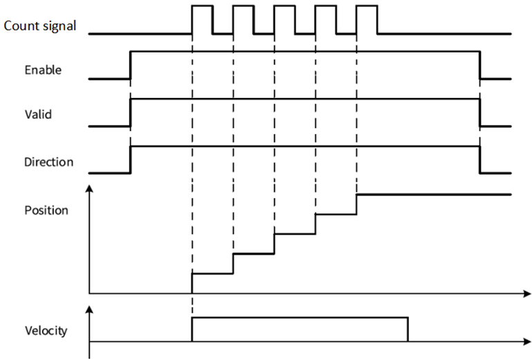
(1) Taking the "pulse+direction" mode as an example, when the direction signal=ON/Invert=FALSE or the direction signal=OFF/Invert=TRUE, the counter counts up. The sequence diagram is shown in the following figure:
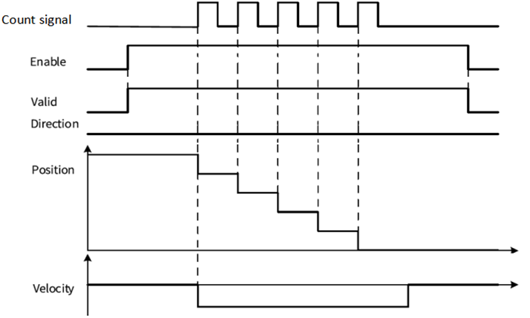
(2)Taking the "pulse+direction" mode as an example, when the direction signal=ON/Invert=TRUE or the direction signal=OFF/Invert=FALSE, the counter counts down. The sequence diagram is shown in the following figure:
Error ID
| Error ID | Content |
| HC_ERROR_ID_POSITION_OVER_POSITIVE_LIMIT | Pulse count position in linear mode exceeds positive limit 140735340871679 |
| HC_ERROR_ID_POSITION_OVER_NEGATIVE_LIMIT | Pulse count position in linear mode exceeds negative limit -140735340871679 |
| HC_ERROR_ID_FPGA_VERSION_ERROR | FPGA version error |
| HC_ERROR_ID_UNDEFINED_COUNTER | High speed counter undefined |
| HC_ERROR_ID_AXIS_IS_REDEFINED | Encoder axis repeat definition |
| HC_ERROR_ID_SUCCESS | No error |
Program example
The counter axis speed is the real-time speed, and the speed unit is Unit/s. The minimum speed that the counter axis can measure is the speed corresponding to one pulse of the counter in 1s. For example, if one pulse of the counter corresponds to 0.01Unit, the minimum measurable speed is 0.01Unit/s.
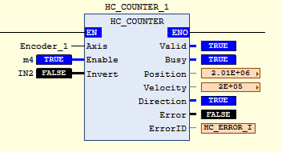
For example: In the above figure, when the current function block Enable is TRUE, the current encoder axis position, speed and display counting direction are updated. The input pulse speed in the current Encoder_1 is measured as 200000 Unit/s, and the current position is 2010000 Unit.