3.6.09 MC_GearInPos
Set the electronic gear ratio between the master axis and the slave axis, and perform the electronic gear operation.
Specify the master axis position to start synchronization, the master axis position and the master axis start synchronization distance, and use this to complete the cutting-in electronic gear action.
Instruction format
| Instruction | MC_GearInPos(FB) | |
| Name | Cut-in electronic gear coupling at designated position | |
| Graphical performance | ST performance | |
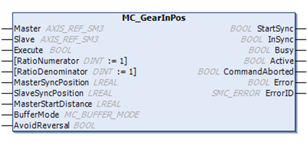
| MC_GearInPos( Master: =, Slave: =, Execute: =, RatioNumerator: =, RatioDenominator: =, MasterSyncPosition: =, SlaveSyncPosition: =, MasterStartDistance =, BufferMode: =, AvoidReversal: =, StartSync=>, InSync=>, Busy=>, Active=>, CommandAborted=>, Error=>, ErrorID=>); | |
Related variables
| Input and output variables | Name | Data type | Effective range | Initial value | Description |
| Master | Master axis | AXIS_REF_SM3 | - | - | Map to an axis, i.e. an instance of AXIS_REF_SM3 |
| Slave | Slave axis | AXIS_REF_SM3 | -
| - | Map to an axis, i.e. an instance of AXIS_REF_SM3 |
| Input variables | Name | Data type | Effective range | Initial value | Description |
| Execute | Instruction execution | BOOL | [FALSE, TRUE] | FALSE | Rising edge, start executing instruction |
| RatioNumerator | Gear ratio molecule | DINT | - | 1 | Numerator of master-slave axis velocity ratio |
| RatioDenominator | Gear ratio denominator | DINT | - | 1 | Denominator of master-slave axis speed ratio |
| MasterSyncPosition | Main axis synchronization position | LREAL | - | - | Master axis position when master-slave gear ratio is coupled |
| SlaveSyncPosition | Slave axis synchronization position | LREAL | - | - | Slave axis position when master-slave axis gear ratio is coupled |
| MasterStartDistance | Perform synchronous master axis position | LREAL | - | - | Salve axis according to the position value and MasterSync Position and SlaveSyncPosition calculate a smooth curve so that the slave axis is in Slave SyncPosition is synchronized with the master axis gear, and the curve master axis range is [MasterStartDistance, MasterSyncPosition] |
| BufferMode | Cache Mode | MC_BUFFIR_MODE | Aborting=0 Buffered=1 BlendingPrevious=3 | 0 | Define the temporal order of FB with respect to the previous block. Only BufferMode Abort, Buffering, and BlendingPrevious are supported. BlendingPrevious means using the configured speed (including direction) of the previous motion as the blending speed, even if the motion has the opposite direction. Only BufferMode=Aborting is allowed if the function block is busy. |
| AvoidReversal | Prohibit reverse | BOOL | [FALSE, TRUE] | FALSE | Set to FALSE, if reversed from the physical position of the axis ahead. Set to TRUE if the axis physically does not achieve reverse or causes damage. Only applicable to the modal axis. If the reversal cannot be avoided, then the axis will stop erroneously. |
| Output variables | Name | Data type | Effective range | Initial value | Description |
| StartSync | Start coupling processing | BOOL | [FALSE, TRUE] | FALSE | TRUE, start electronic gear coupling process |
| InSync | In coupling | BOOL | [FALSE, TRUE] | FALSE | TRUE, the electronic gear coupling process is complete, and the gear ratio of the master and slave axis is coupled |
| Bus | Execution flag | BOOL | [FALSE, TRUE] | FALSE | TRUE, instruction is being processed |
| Active | Under control | BOOL | [FALSE, TRUE] | FALSE | TRUE, under control |
| CommandAborted | Instruction abort | BOOL | [FALSE, TRUE] | FALSE | Interrupted by other control instructions |
| Error | Error | BOOL | [FALSE, TRUE] | FALSE | When an error occurs, set to TRUE |
| ErrorID | Error ID | SMC_ERROR | Refer to SMC_ERROR | 0 | When an error occurs, the error ID is output. |
Function description
(1) The operation target axis is designated by Slave, and the RatioNumerator, the RatioDenominator, the Acceleration, and the Deceleration are designated to perform the gear operation.
(2) An instruction position, a feedback position, and a latest instruction position can be specified to the Master axis.
(3) Execute rising edge starts the electronic gear action.
(4) After the operation is started, the Slave axis performs an acceleration/deceleration operation with the speed obtained by multiplying the Master axis speed by the gear ratio as the target speed.
(5) The process from the start to the end of synchronization in this function block is essentially an electronic cam thatthe slave axis follows the master axis within the synchronization interval.. At this time, according to the master axis range (MasterSyncPosition-MasterStartDistance, MasterSyncPosition), from the axis range (current position, SlaveSyncPosition), the instruction will automatically design a cam curve according to the set gear ratio and the above three parameters, and slave axis follows the master axis to complete the cam action when performing synchronization.
(6) Note : If the master-slave axis works in linear mode, it is necessary to ensure that the above parameters are set reasonably, otherwise the gear action cannot be carried out correctly. Therefore, it is recommended that the master-slave axis works in periodic mode when using this instruction.
For example: Both the master and slave axes move forward in linear mode. When the instruction is executed, if the master axis position >MasterSyncPosition-MasterStartDistance, or slave axis position>SlaveSyncPosition cannot cut in the electronic gear action.
Sample sequence diagrams in several different parameters are given below:
When the master axis is operating in periodic mode (360 cycles) and the slave is operating in periodic mode (360 cycles):
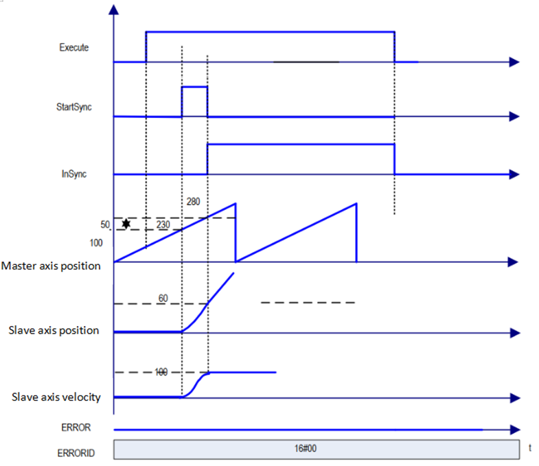
1. MasterSyncPosition=280, MasterStartDistance=50, SlaveSyncPosition =60, spindle speed is 50, AvoidReversa=FALSE.
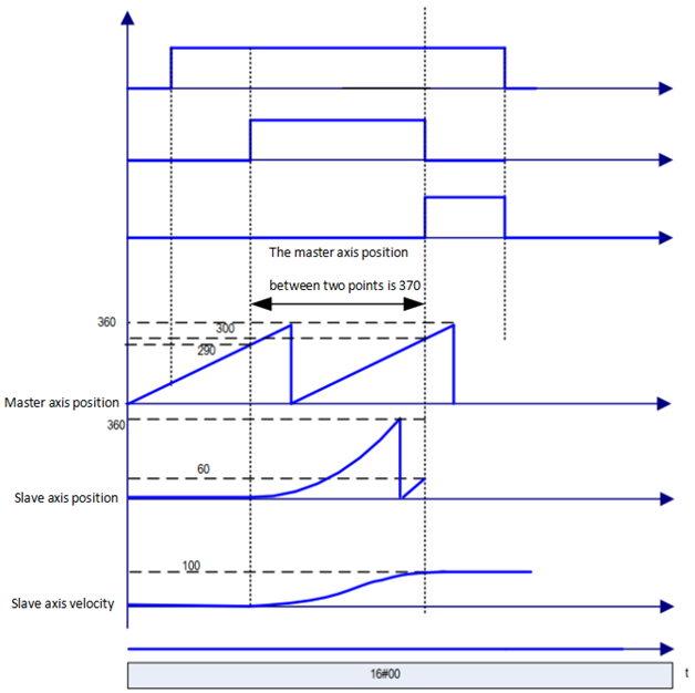
2. MasterSyncPosition=300, MasterStartDistance=370, SlaveSyncPosition=60, spindle speed is 50, AvoidReversal=FALSE.
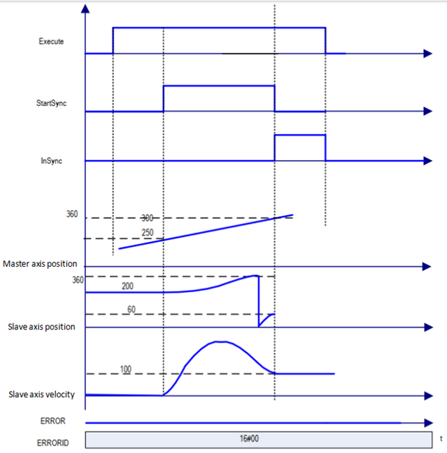
3. MasterSyncPosition=300, MasterStartDistance=50, SlaveSyncPosition=60, master axis speed is 50, AvoidReversal=FALSE, from axis start position greater than 60.
The target speed is reached while the synchronization is completed (InSync is TRUE), then the amount of movement from slave axis=amount of movement from master axis*RatioNumerator/RatioDenominator.
For AvoidReversal: If the slave axis is a modal axis and the master axis speed (a multiple of the gear ratio) is not a speed relationship with respect to the slave axis, then MC_GearInPos instruction attempts to avoid the reversal of the slave axis. It attempts to "stretch" the motion of the slave axis by adding 5 slave axis cycles. If this "stretch" is not valid, then an error will occur and stop from the axis incorrectly.
If the master axis speed is associated with the slave axis speed (which is a multiple of the gear ratio), an error occurs and the axis stops in error.
If the slave axis is a linear axis mode axis, an error will occur when the Execute input rising edge is processed.
Precautions
When you want to use MC_SetPosition insturction for Master axis, disengage the relationship between the spindle and the slave axes and execute the instruction.
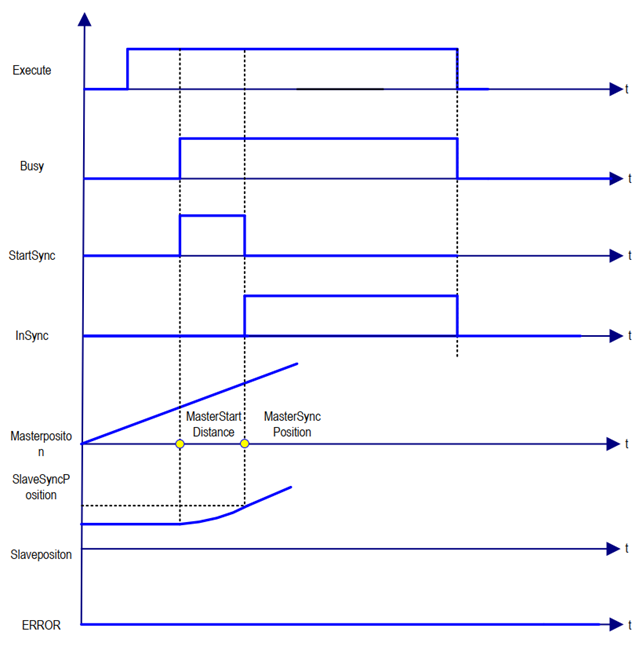
Sequence diagram
On the rising edge of starting Execute, the electronic gear action is started. Busy becomes TRUE at the same time as Execute is started. Once the action is started, Active (in control) and StartSync (in tracking) start the gear action. When you reach MasterSyncPosition, SlaveSyncPosition, InSync becomes TRUE. When this instruction is interrupted with another instruction, CommandAborted becomes TRUE and Busy, Active, StartSync, and InSync becomes FALSE.
This instruction starts in other instruction execution
Start this instruction for the currently executing instruction, which can be switched or cached to this instruction.
The action at launch of multiple instances of this instruction is specified by BufferMode.
| Buffer mode selection | Description |
| Aborting | Immediately abort the currently executing instruction and switch to this instruction. When the operation direction of the axis is reversed due to the instruction switching, the operation direction of the axis is reversed according to "operation at the time of reverse" in the axis parameter. |
| Buffered | The function block is started immediately after the last instruction motion is terminated. No blending is done here. When the end condition (Done, InVelocity, InEndVelocity, InGear, InSync, EndOfProfile, etc.) is reached, the new motion starts at the speed of the previous motion. If the previous motion was MC_MoveAbsolute or MC_Move Relative, then the new movement begins at rest. |