LX3V-4PT
1 Introduction
The LX3V-4PT V2 analog block amplifies the input from four platinum temperature sensors (PT 100, 3 wires, and 100 Ω) and converts the data into 12 bit reading’s stored in the Main Processing Unit (MPU). Both Centigrade (°C) and Fahrenheit (°F) can be read. Reading resolution is 0.2°C to 0.3°C / 0.36°F to 0.54°F.
All data transfer and parameter settings can be controlled and adjusted by the software of the LX3V-4PT V2, which is done by the TO/FROM application instructions of the LX3V main unit.
LX3V-4PT V2 consumes 5V voltage from LX3V main unit or active extension unit, 90ma current of power supply.
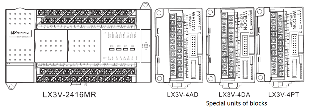
2 Dimensions
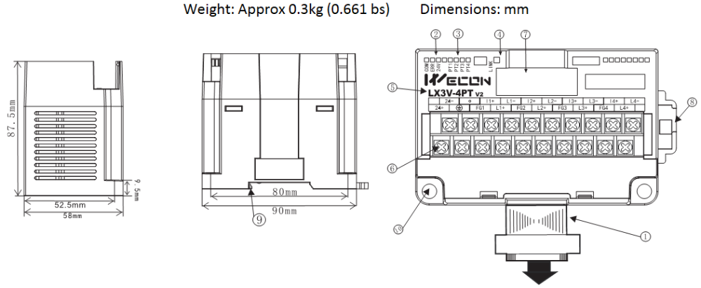
- Extension cable and connector
- Com LED & 24V LED: Light when communicating& light when connect to 24V
- PT LED: Channels indicator
- LINK: Indicator between PLC and module
- Module name
- Analog signal output terminal
- Extension module interface
- DIN rail mounting slot
- DIN rail hook
- Mounting holes (φ4.5)
| Name | Description | States | ||
|---|---|---|---|---|
| Blink | OFF | ON | ||
| COM | Indicator of communication board and acquisition board | Communicating | Communication failed or abnormal | -- |
| ERR | Factory calibration lamp | -- | Calibrated | Not calibrated |
| 24V | Power lamp | -- | Abnormal | Normal |
| LINK | Communication indicator between PLC and module | Communicating | Communication failed or abnormal | Software failure or hardware failure |
| PT 1 | Channel 1 lamp | Temperature exceeds range or the channel is not connected | Channel is closed | Temperature is in normal range |
| PT 2 | Channel 2 lamp | |||
| PT 3 | Channel 3 lamp | |||
| PT 4 | Channel 4 lamp | |||
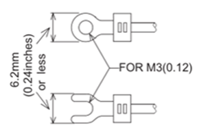
Using crimp terminations
- Be sure to use the crimp-style terminals that satisfy the dimensional requirements shows in the left figure.
- Apply 0.5 to 0.8 N.m (5 to 8 kgf.cm) torque to tighten the terminals to prevent abnormal operation.
3 Terminal Layouts
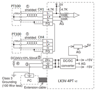
- The cable of the PT100 sensor or a twisted shielded cable should be used for the analog input cable. This analog input cable should be wired separately from power lines or any other lines which may induce noise.The three wire method improves the accuracy of the sensor by compensating voltage drops.
- If there is electrical noise, connect the frame ground terminal (FG) with the ground terminal.
- Connect the ground terminal on the LX3V-4PTV2 unit with the grounded terminal on the base unit. Use class 3 grounding on the base unit, if grounding is possible.
- Either an external or the 24V built-in supply in the programmable controller may be used.
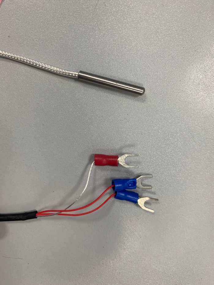
For example: the same color wire (red) is connected to I+ and L+ terminals, and the white wire is connected to L-
For additional data regarding EMC considerations please see section 7.0
4 Installation instruction
Environmental specification
| Item | Specification |
|---|---|
| Environmental specifications (excluding following) | Same as those for the LX3V base unit |
| Dielectric withstand voltage | 500V AC, 1min (between all terminals and ground) |
Power supply specification
| Item | Description |
|---|---|
| Analog circuits | ±24V DC±10%,55ma |
| Digital circuits | 5V DC,90ma(internal power supply from base unit) |
Performance specification
| Item | Centigrade | Fahrenheit |
|---|---|---|
| Both °C and °F readings are available by reading the appropriate buffer memory area. | ||
| Analog input signal | Platinum temperature PT 100 sensors (100 Ω), 3-wire, 4-channel (CH1, CH2,CH3, CH4), 3850 PPM/°C | |
| Current to sensor | 1 ma. Sensor : 100 Ω PT 100 | |
| Compensated range | 100°C to 600°C | -148°F to +1112°F |
| Digital output | -1000 to 6000 | -1480 to 11120 |
| 12-bit conversion 11 data bits +1 sign bit | ||
| Minimum resolvable temp. | 0.2°C to 0.3°C | 0.36°F to 0.54°F |
| Overall accuracy | ±1% full scale (compensated range) -see section 7.0 for special EMC considerations | |
| Conversion speed | 4 channels 15ms | |
Analog input
| Feature Conversion |
|
|---|
Other
| Item | Description |
|---|---|
| Isolation | Photo-coupler isolation between analog and digital circuits. DC/DC converter isolation of power from LX3V MPU. No isolation between analog channels. |
| Total points | 8 points taken from the LX3V expansion bus (can be either inputs or outputs) |
Buffer memory
| BFM | Description |
|---|---|
| *#1→ #4 | CH1 to CH4 Averaged temperature reading to be averaged (1 to 4,096) Default = 8 |
| *#5→ #8 | CH1 to CH4 Averaged temperature in 0.1°C units |
| *#9→ #12 | CH1 to CH4 Present temperature in 0.1°C units |
| *#13→ #16 | CH1 to CH4 Averaged temperature in 0.1°F units |
| *#17→ #20 | CH1 to CH4 Present temperature in 0.1°F units |
| *#21→ #27 | Reserved |
| *#28 | Digital range error latch |
| #29 | Error status |
| #30 | Identification code K2040 |
| #31 | Software version |
- The numbers of samples to be averaged are assigned in BFMs #1 to #4. Only the range 1 to 4096 is valid. Values outside this range are ignored. The default value of 8 is used.
- A number of recently converted readings are averaged to give a smoother read out. The averaged data is stored in BFMs #5 to #8 and #13 to #16.
- BFMs #9 to #12 and #17 to #20 store the current value of the input data. This value is in units of 0.1°C or 0.1°F, but the resolution is only 0.2°C to 0.3°C or 0.36°F to 0.54°F.
States information
Buffer memory BFM#28: Digital range error latch
- BFM #29 b10 (digital range error) is used to judge whether the measured temperature is within the unit’s range or not.
- BFM #28 latches the error status of each channel and can be used to check for thermocouple disconnection.
| B15 or b8 | B7 | B6 | B5 | B4 | B3 | B2 | B1 | B0 |
|---|---|---|---|---|---|---|---|---|
| Not used | High | Low | High | Low | High | Low | High | Low |
| CH4 | CH3 | CH2 | CH1 | |||||
- Low: Latches ON when temperature measurement data goes below the lowest temperature measurement limit.
- High: Turns ON when temperature measurement data goes above the highest temperature measurement limit, or when a thermocouple is disconnected.
When an error occur the temperature data before the error is latched. If the measured value returns to within valid limits the temperature data returns to normal operation. (Note: The error remains latched in (BFM #28))
An error can be cleared by writing K0 to BFM #28 using the TO instruction or turning off the power.
Buffer memory BFM#29: Error states
| BFM#29 Bit device | ON | OFF |
|---|---|---|
| B0: Error | When any of b1 to b3 is ON A/D conversation is stopped for the error channel | No error |
| B1: Reserved | Reserved | Reserved |
| B2: Power source | 24V DC power supply failure | Power supply normal |
| B3: Hardware error | A/D converter or other hardware failure | Hardware normal |
| B4 to b9: Reserved | Reserved | Reserved |
| B10: Digital range error | Digital output/analog input value is outside the specified range. | Digital output value is normal |
| B11: Averaging error | Selected number of averaged results is outside the available range. See BFM#1 to #4 | Averaging is normal (between 1 to 4096) |
| B12 to b15: Reserved | Reserved | Reserved |
Identification Code Buffer Memory BFM #30
The identification code or ID number for module is read from buffer memory BFM #30 using the FROM command.
This number for the LX3V-4PT V2 unit is K2040.
The programmable controller can use this facility in its program to identify the special block before commencing data transfer from and to the special block
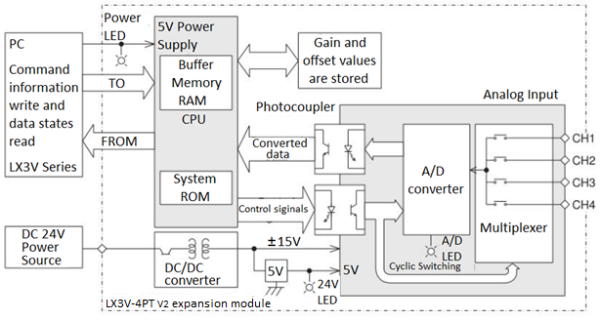
System diagram
5 Example
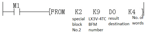
In the program shown below, the LX3V-4PT V2 expansion module occupies the position of special block number 2 (that is the third closest block to the programmable controller). The averaging amount is four. The averaged values in degrees C of input channels CH1 to CH4 are stored respectively in data registers D0 to D3.
Example 1
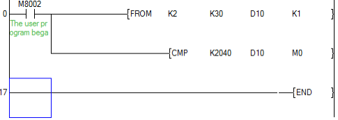
This initial step checks that the expansion module placed at position 2 is actually an LX3V-4PT V2, i.e. Its unit identification number is 2040 (BFM #30). This step is optional, but it provides a software check that the system has been configured correctly.
Block No.2 BFM #30→(D10)
When (K2040)= (D10), M1=ON. i.e. when identification code is K2030, M1=ON.
Example 2
Transfer the error status to (M25 to M10), when error is found, M10=ON
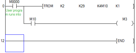
This step provides optional monitoring of the LX3V-4PT V2 Error Buffer Memory (#29). If there is an Error on the LX3V-4PT V2, bit b0 of BFM #29 will be set on. This can be read by this program step, and output as a bit device in the PLC (Y010 in this example). Additional Error devices can be output in a similar manner, e.g. B10 BFM #29 Digital range error. (See example 3)
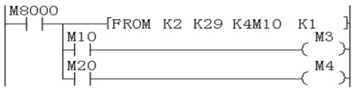
Example 3
M10 represents b0 of BFM#29
M20 represents b10 of BFM#29
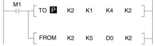
- (K4)-> (BFM#1), (K4)-> (BFM#2). Number of samples is changed to 4 on both CH1 and CH2.
- (BFM#5)-> (D0), (BFM#6)-> (D1). Transfer the average temperature value in °C to the data registers.
This step is the actual reading of the LX3V-4PT V2 input channels. It is essentially the only program step which is needed. The "TO" instruction in this example, sets the input channels, CH1 and CH2, to take the average reading of four samples.
The "FROM" instruction reads the average temperatures (BFM #5 to #8) for input channels CH1 and CH2 of the LX3V-4PT V2. If direct temperature readings are required BFM #9 and #10 should be read instead, e.g.
6 Diagnostics
Preliminary checks
- Check whether the input wiring and/or extension cables are properly connected on LX3V-4PT V2 analog special function block.
- Check that the LX3V system configuration rules have not been broken, i.e. The number of special function blocks does not exceed 16 and the total system I/O is equal or less than 256 I/O.
- Ensure that the correct operating range has been selected for the application.
- Check that there is no power overload on either the 5V or 24V power sources, remember the loading on a LX3V main unit or a powered extension unit varies according to the number of extension blocks or special function blocks connected.
- Put the LX3V main unit into RUN.
Error checking
- If the LX3V-4PT V2 special function block does not seem to operate normally, check the following items.
Check the status of the POWER LED.
Lit: The extension cable is properly connected.
Otherwise: Check the connection of the extension cable.
- Check the external wiring.
- Check the status of the “24V” LED (top right corner of the LX3V-4PT V2 ).
Lit: LX3V-4PT V2 is OK; 24V DC power source is OK.
Otherwise: Possible 24VDC power failure, if OK possible LX3V-4PT V2 failure.
- Check the status of the “A/D” LED (top right corner of the LX3V-4PT V2).
Lit: A/D conversion is proceeding normally.
Otherwise: Check buffer memory #29 (error status). If any bits (b2 and b3) are ON, then this is why the A/D LED is OFF.
Checking special function block numbers
Other special units of blocks that use FROM/TO commands, such as analog input blocks, analog output blocks and high-speed counter blocks, can be directly connected to the base unit of the LX3V programmable controller or to the right side of other extension blocks or units. Each special block is consecutively numbered from 0 to 15 beginning from the one closest to the base unit. A maximum of 16 special blocks can be connected.
7 EMC considerations
- Electromagnetic compatibility or EMC must be considered before using the LX3V-4PT V2.
- WECON recommends that the thermocouple sensors used, should be fitted with a form of seild or screening as protection against EMC noise.
- If some form of cable protection is used, the “Shield” must be terminated at the terminals as shown in chapter 3.
- Because of the delicate nature of all analog signals, failure to take good EMC precautions could lead to EMC noise induced errors; up to ±10% of actual values. This is an absolute worst case figure, users who do take good precautions can expect operation within normal tolerances. EMC considerations should include selection of good quality cables, good routing of those cables away from potential noise sources.
- Additionally it is recommended that signal averaging is used as this will reduce the effects of random noise “spikes”