

1 Introduction
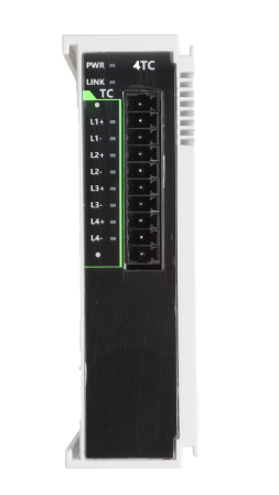
LX6V to 4TC (4-channal analog inputs), used for the acquisition of thermocouple input analog signals. Suitable for Wecon LX6 series PLC and LX6V to EM to ECAT module equipment
Upper computer software version that supports this module: 2.6. 236 and above, PLC firmware version: 2.321. 1032 and above.
LX6V to EM to ECAT firmware version that supports this module: V2.022 and above, and the corresponding XML version is 1.3 and above.
✎Note: The total power of expansion modules connected to LX6 series PLC and LX6V to EM£ to ECAT cannot be greater than 48W.
2 Appearance and terminal description
2.1 Appearance and size
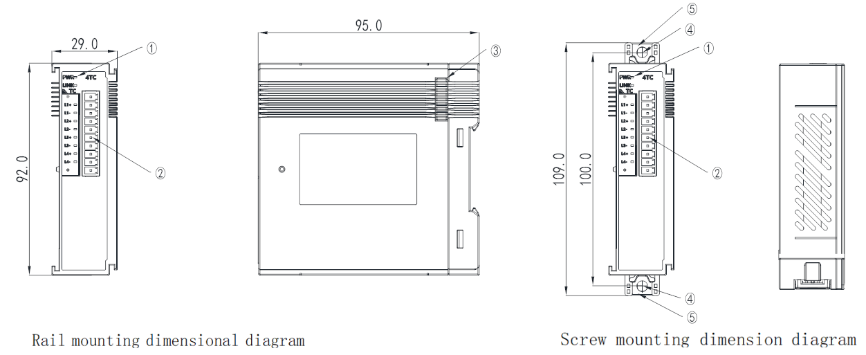
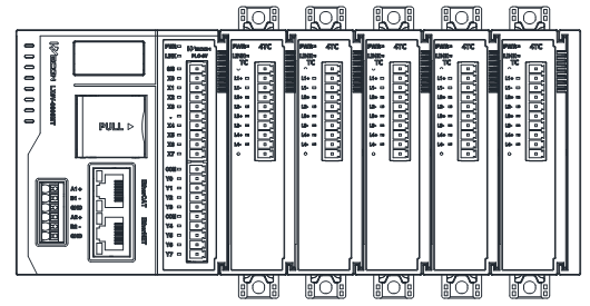
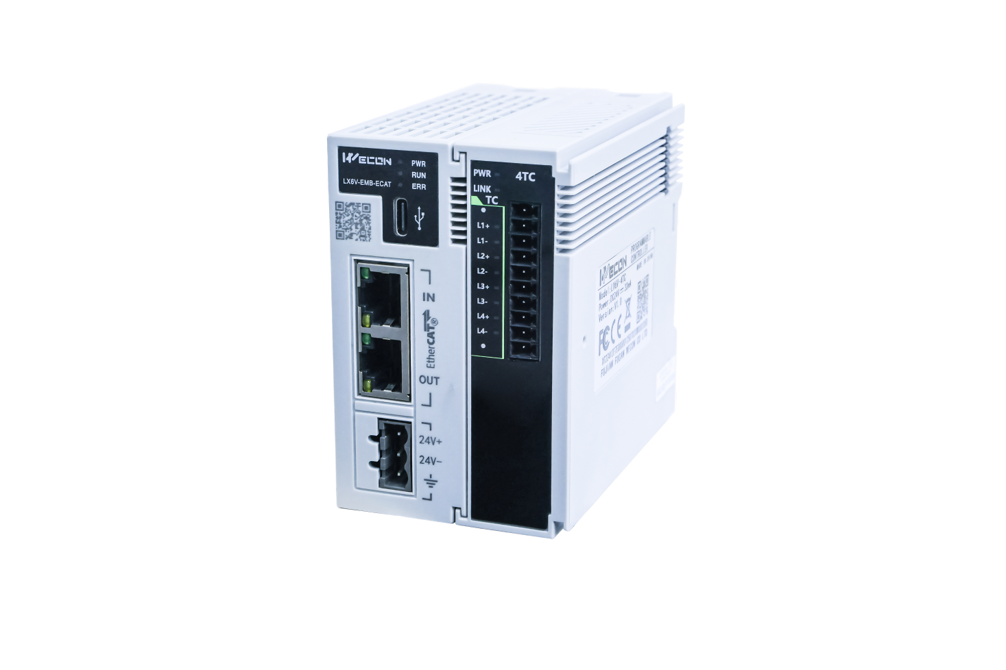
① LED; ② Terminal; ③ Expansion module interface; ④ Mounting hole:2 (Φ4.5); ⑤ DIN rail clip.
2.2 Terminal description
The 4TC expansion module terminal are arranged as follows:
| Module model | Terminal arrangement | |
| LX6V to 4TC | 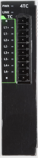 | 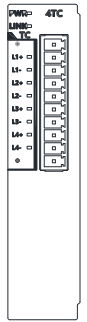 |
2.3 Installation
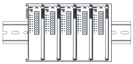
Please install the end cover on the right side of the last expansion module, align it with the module interface slot and connect it, as shown in the figure below:
2.4 Indicator
The 4TC expansion module LED is shown below:
| Indicator lamp | Description |
| PWR | Always lights up when the module is powered on normally. |
| LINK light | Communication indicator light between the expansion module and PLC. Lights out: Data interaction is abnormal, stopped, or failed Lights on: Data interaction is normal. |
| Ln + | Defined as: Status light. Light up to indicate channel enabled; Flashing is used to indicate that the channel is overlimit and disconnection. |
| Ln - | N/A |
3 Parameter specifications
3.1 Input specifications
| Item | Specification |
| Input channel | 4 |
| Digital resolution | 16 bit |
| Sensitivity | 0.1℃, 01℉ |
| Input terminal | Thermocouple input, thermocouple type: K, J, E, B, N, R, S, T |
| Compensation method | Internal cold junction compensation |
| Accuracy (normal temperature 25 ℃) | Full range ±0.1% + cold junction compensation error |
| Accuracy (working temperature to 20 ℃to 55 ℃) | Full range ±0.3% + cold junction compensation error |
| Isolation or not | Isolation between I/O terminals and power supply, isolation between channels |
| Overlimit disconnection detection | Support |
| Power consumption | < 0.8 W |
| Power supply | Power supply via interface, DC24V ± 10%, 32mA |
3.2 Environmental specification
| Item | Specification | ||||
| Usage environment | No corrosive, combustible gas, no large amount of conductive dust | ||||
| Environment temperature | Working temperature: 0℃ to 55℃ Storage temperature: - 20℃ to 70℃ | ||||
| Environment humidity | Working humidity: 10% to 90%RH (no condensation) Storage humidity: ≤ 90% RH (no condensation) | ||||
| Installation | Snap mount on DIN46277 (width 35mm) rail or direct positioning hole mount | ||||
| Vibration resistance | According to JISC0040 standard | ||||
| Frequency | Acceleration | Amplitude | X, Y, Z 10 times in each of three directions (80 minutes in each direction) | ||
| DIN rail installation | 10 to 57Hz | - | 0.035 mm | ||
| 57 to 150Hz | 4.9 m/S2 | - | |||
| Direct installation | 10 to 57Hz | - | 0.075 mm | ||
| 57 to 150Hz | 9.8 m/S2 | - | |||
| Shock resistance | Compliant with JISC0041 standard (147 m/S2, action time 11 ms, three sinusoidal half to wave pulses in each of X, Y, and Z directions) | ||||
| EMC immunity level | Zone B lEC 61131 to 2 | ||||
| Altitude requirements | ≤ 2000 m (80 kPa) | ||||
| Protection level | IP20 | ||||
| Grounding | Not co - located with the strong current system | ||||
3.3 Software specification
| Item | Specification |
| Input PDO data volume | Maximum 24 byte |
| Diagnostic reporting function configuration | Support |
| Diagnostic detection enable configuration | Support overlimit and disconnection detection |
| Sensor type configuration | Support thermocouple module type: K, J, E, B, N, R, S, T, default to K to type thermocouple |
| Filter time | 0s to 100s (can be configured by software, default 5s) |
| Overflow detection | Supports reporting overflow status only when overflow is enabled |
| Overlimit detection enable configuration | Support |
| Independent channel configuration | Support |
| Temperature offset enable configuration | Support |
| Temperature offset configuration range | -300 to +300, temperature unit |
| Display mode | Celsius (℃), Fahrenheit (℉) |
| Display sensitivity | 0.01℃, 0.01℉ |
| Sample refresh | Refresh asynchronously according to the sampling time, do not require synchronization refresh according to the bus cycle |
| Stop mode | Output according to the maximum value, no more refresh |
| Disconnected or ovelimit | Output according to the maximum value, no more refresh |
| System diagnostics | System power abnormality |
| Channel diagnosis | Over upper limit alarm, over lower limit alarm, disconnection alarm, overflow alarm |
| Configuration diagnostics | Configuration error identification, channel parameter configuration error |
3.4 Accuracy calculation
Within the working temperature range, when the temperature change rate is less than 0.3 °C/min, the accuracy of this product = ADC sampling accuracy + cold junction compensation error. According to the test principle, it is need to wait for the module to be powered on for 45 minutes before measuring.
Recommended: Within the working temperature range and under the condition of horizontal and vertical installation direction, when the adjacent module is a temperature module, the cold end compensation error is within ±3℃.
Not recommended: Adjacent modules consume more than 3.5 W of power, for example host PLC, LX6V - 32EXYT.
| Installation direction | Adjacent module type | Cold junction compensation error ( - 20 ℃ to 0 ℃) | Cold junction compensation error (0 ℃ to 55 ℃) |
| Horizontal installation | Temperature module | ± 0.8℃ | ± 1.1℃ |
| Non - temperature module | ± 0.6℃ | ± 2.8℃ | |
| Non - horizontal installation | Temperature module | ± 1.1℃ | ± 2.8℃ |
| Non - temperature module | ± 1.37℃ | ± 4.9℃ |
4 Usage
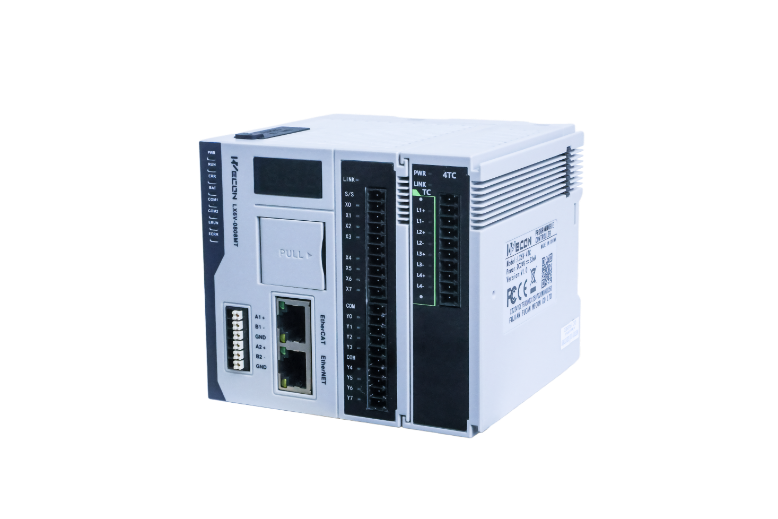
This module is suitable for Wecon LX6 series PLC and LX6V - EM£ - ECAT module equipment. The two usage methods are as follow.
4.1 Use on LX6V/LX6S
The parameter configuration interface is as below:
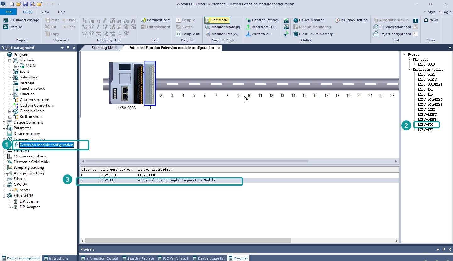
Upper computer expansion module configuration process description:
① Double - click the expansion module configuration to open the configuration interface;
② Adding new modules according to the model and position of the current module connected;
③ Double - click the module in the current machine slot to open the parameter configuration interface;
- TC general configuration
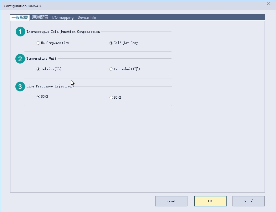
① Thermocouple cold junction compensation: Set whether the module enables cold junction compensation, and the cold junction compensation is enabled by default;
② Temperature unit: Set the temperature unit output by the module, and the supported temperature unit types are Celsius (℃) or Fahrenheit (℉), the default unit is: Celsius;
③ Power frequency suppression: Set the power frequency suppression of the module to suppress 50Hz or suppress 60Hz. The default suppression is 50Hz. Please set the appropriate power frequency suppression option for the module according to the actual application scenario;
2. TC channel configuration
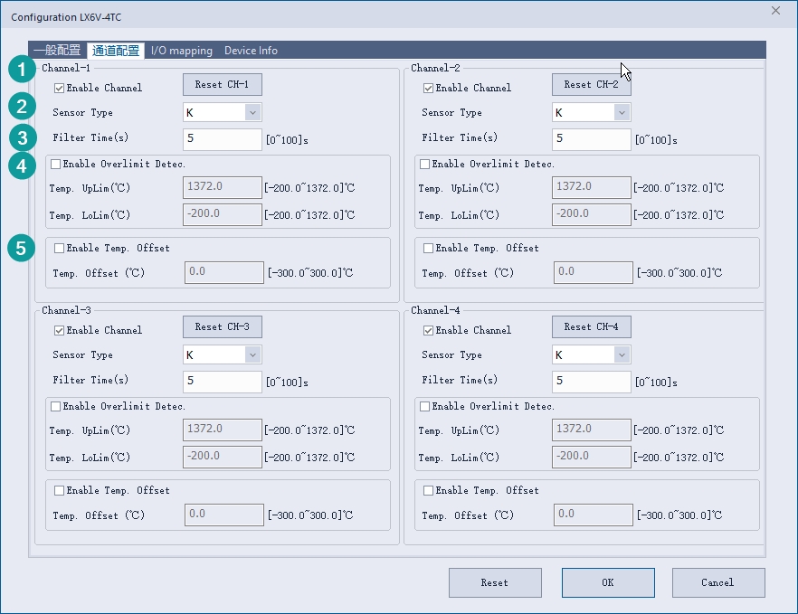
① Enable channels: It can be set whether to enable the current expansion module channel;
② Sensor type: Set the sensor type connected to the module channel, the default sensor type is K to type, there are 8 types of sensors supported by TC module, which are: K, J, E, B, N, R, S, T; The temperature range that can be measured by each sensor is as follows:
| Sensor type | Temperature range | |
| Degree Celsius | Degree Fahrenheit | |
| K | - 200℃ to 1372℃ | - 328.0℉ to 2501.6℉ |
| J | - 200℃ to 1000℃ | - 328.0℉ to 1832.0℉ |
| E | - 200℃ to 1000℃ | - 328.0℉ to 1832.0℉ |
| B | 400℃ to 1820℃ | 752.0℉ to 3308.0℉ |
| N | - 200℃ to 1300℃ | - 328.0℉ to 2372.0℉ |
| R | - 50℃ to 1768℃ | - 58.0℉ to 3214.4℉ |
| S | - 50℃ to 1768℃ | - 58.0℉ to 3214.4℉ |
| T | - 200℃ to 400℃ | - 328.0℉ to 752.0℉ |
③Filtering time: The supported filtering time is 0 to 100s, it is used to reduce fluctuations in channel temperature data. The default filtering time is 5s. Please choose the appropriate filtering time according to the requirements of actual application scenarios for channel output data;
④ Enable overlimit detection: Channel temperature data overlimit judgment switch, when overlimit detection is enabled, the upper and lower limits of temperature can be set. When the temperature output by the channel is greater than the upper limit of temperature or less than the lower limit of temperature, the state of this channel will output a channel over to limit warning;
⑤ Enable temperature offset: Channel temperature data offset enable switch. When temperature offset is enabled, the output temperature data of the channel will be offset;
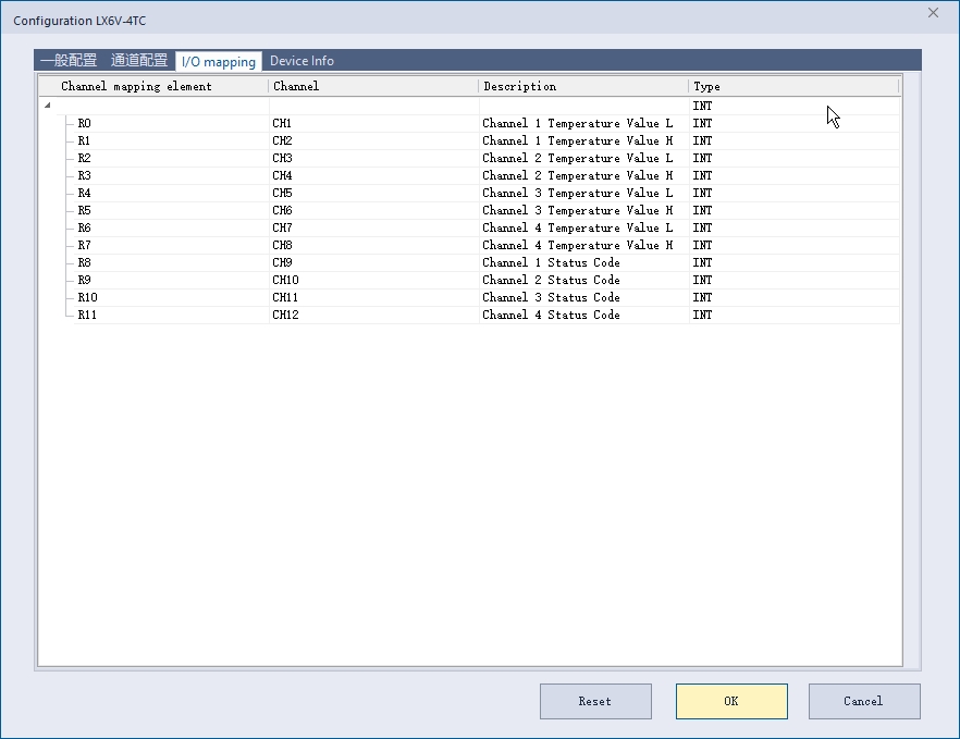
3. I/O mapping
By default, channel are mapped into the R device according to the current number of module channels. The following figure shows the mapping of the modules CH1 to CH12 to the R0 to R11 device. The temperature value data type of the channel is REAL. If it is necessary to display the channel 1 The temperature value can be viewed after assigning a variable using the DEMOV instruction.
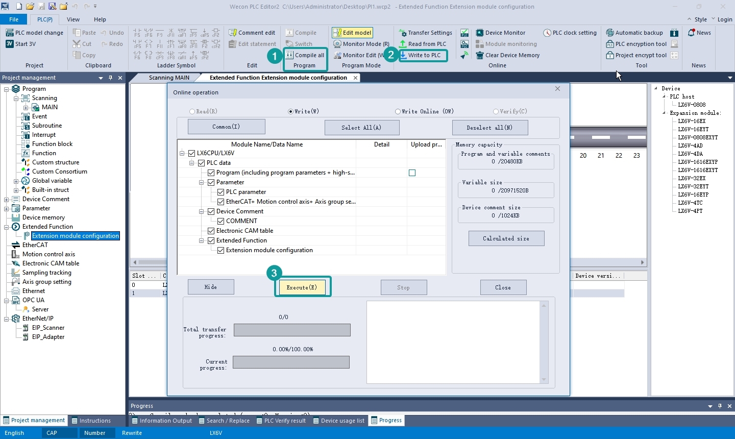
4. Download configuration
Click OK to save the configuration,according to the interface shown in the figure to download the module configuration to the PLC.
4.2 Used on LX6V to EM□ to ECAT module
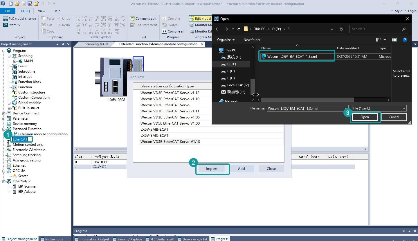
- First add EtherCAT device
According to steps ① to ④ in the figure below, right to click EtherCAT, and click [New] to >[Import] to import the ESI device description file of the device;
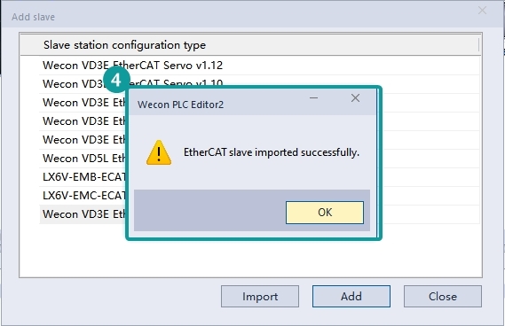
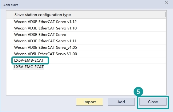
After the import is completed, select the coupler according to themodule model and location connected to PLC (the figure below takes LX6V to EMB to ECAT as an example);
- Configuration module
Right to click the currently added coupler to add the expansion module mounted to the current coupler.
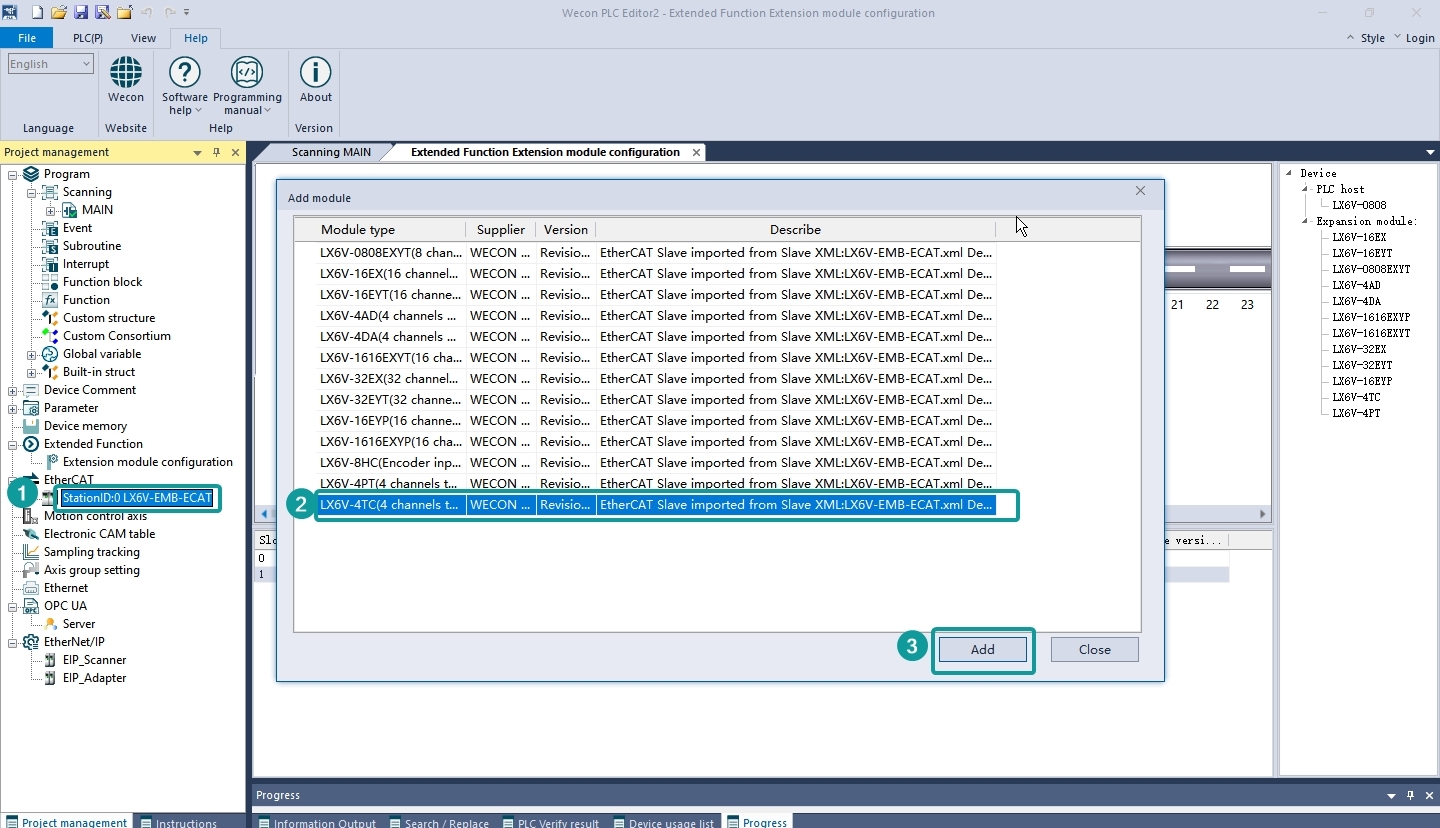
✎Note: When the configuration module is inconsistent with the actual mounted module, an error will be reported that the OP cannot be successful.
- Configure module parameters
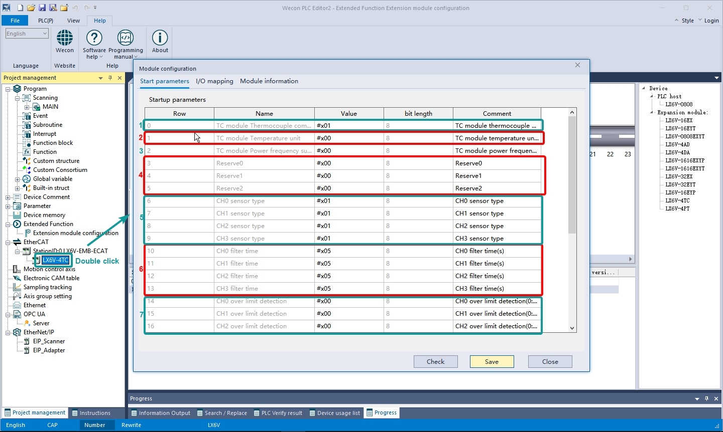
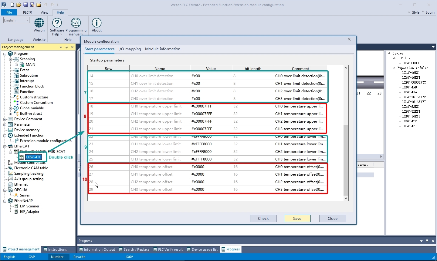
General configuration
① TC module thermocouple compensation: Set whether the module enables cold junction compensation, and the cold junction compensation is enabled by default;
0: No cold junction compensation;
Others: Enable cold junction compensation;
② TC module temperature unit: Set the temperature unit output by the module. The supported temperature unit types are Celsius (℃) or Fahrenheit (℉). The default unit is: Celsius;
0: Degrees Celsius (℃);
Others: Degrees Fahrenheit (℉);
③ TC module power frequency support: Set the power frequency suppression of the module to suppress 50Hz or suppress 60Hz, and the default suppression is 50Hz;
0: Suppress 50 Hz;
Others: Suppress 60 Hz;
④ Reserve: Reserve;
⑤ CHx sensor type: Set the type of sensor connected to the channel;
Supported sensor types:
0: Not enabled
1: K;
2: J;
3: E;
4: B;
5: N
6: R
7: S
8: T
⑥ CHx filtering time: Used to specify the filtering time of the current channel. The supported filtering time is 0 to 100s, it is used to reduce the fluctuation of channel temperature data. The default filtering time is 5s;
⑦ CHx overlimit detection: Overlimit detection enables configuration, 0: Overlimit detection detection is not enabled, others: Enable over limit detection
⑧ CHx temperature upper limit: The upper limit value of the channel over limit detection temperature;
⑨ CHx temperature lower limit: The lower limit value of the channel overlimit detection temperature;
⑩ CHx temperature offset: The offset of channel data, supported offset range: - 300 to + 300;
I/O mapping
The temperature and state of the module can be mapped to variables/device. For example, the following figure maps the temperature values of the CH0 to CH3 channels to the D0 to D7 device, and the status codes of the CH0 to CH3 channels to the D8 to D11 device.
Click save configuration and download the configuration to PLC.
5 Object dictionary
| Model | Index | Sub - index | Description | Data Type | Range | Read - write | Unit | Default | Name |
| LX6V - 4TC | 16#8000 | 16#01 | TC module thermocouple cold junction compensation 0: No compensation Others: Cold junction compensation | UINT8 | 0 to 255 | W | - | 1 | TC module thermocouple compensation |
| 16#02 | TC module temperature unit 0: Degrees Celsius (℃) Others: Degrees Fahrenheit (℉) | UINT8 | 0 to 255 | W | - | 0 | TC module temperature unit | ||
| 16#03 | TC module power frequency suppression 0: Suppress 50 Hz Others: Suppress 60Hz | UINT8 | 0 to 255 | W | - | 0 | TC module power frequency suppression | ||
| 16#04 | Reserve parameter 0 | UINT8 | 0 to 255 | W | - | 0 | Reserve 0 | ||
| 16#05 | Reserve parameter 1 | UINT8 | 0 to 255 | W | - | 0 | Reserve1 | ||
| 16#06 | Reserve parameter2 | UINT8 | 0 to 255 | W | - | 0 | Reserve 2 | ||
| 16#8001 | 16#01 | Sensor type 0: Disable 1: K 2: J 3: E 4: B 5: N 6: R 7: S 8: T Others: Not supported | UINT8 | 0 to 8 | W | - | 1 | CH0 sensor type | |
| 16#02 | CH1 sensor type | ||||||||
| 16#03 | CH2 sensor type | ||||||||
| 16#04 | CH3 sensor type | ||||||||
| 16#8002 | 16#01 | TC module channel filtering time: 0 to 100s Others: 100s | UINT8 | 0 to 255 | W | s | 5 | CH0 filter time | |
| 16#02 | CH1 filter time | ||||||||
| 16#03 | CH2 filter time | ||||||||
| 16#04 | CH3 filter time | ||||||||
| 16#8003 | 16#01 | Overlimit detection enable 0: Disable Others: Enable | UINT8 | 0 to 255 | W | - | 0 | CH0 overlimit detection | |
| 16#02 | CH1 overlimit detection | ||||||||
| 16#03 | CH2 overlimit detection | ||||||||
| 16#04 | CH3 overlimit detection | ||||||||
| 16#8004 | 16#01 | Temperature unit: 0.1℃/0.1℉ The upper and lower limits of sensors are different for each model | INT32 | -2147483648 to 2147483647 | W | - | 32767 | CH0 temperature upper limit | |
| 16#02 | CH1 temperature upper limit | ||||||||
| 16#03 | CH2 temperature upper limit | ||||||||
| 16#04 | CH3 temperature upper limit | ||||||||
| 16#8005 | 16#01 | INT32 | -2147483648 to 2147483647 | W | - | -32768 | CH0 temperature lower limit | ||
| 16#02 | CH1 temperature upper limit | ||||||||
| 16#03 | CH2 temperature upper limit | ||||||||
| 16#04 | CH3 temperature lower limit | ||||||||
| 16#8006 | 16#01 | Offset temperature value (0.1 ℃/0.1 ℉) 0: No offset | INT16 | 3000 to 3000 | W | - | 0 | CH0 temperature offset | |
| 16#02 | CH1 temperature offset | ||||||||
| 16#03 | CH2 temperature offset | ||||||||
| 16#04 | CH3 temperature offset | ||||||||
| 16#A000 | 16#00 | Module status information | UINT16 | - | R | - | - | Module status | |
| 16#01 | Version code | UINT16 | - | R | - | - | Version | ||
| 16#02 | Error status | UINT16 | - | R | - | - | Run status | ||
| 16#03 | Channel status | UINT16 | - | R | - | - | Channel status | ||
| 16#6000 | 16#01 | Current temperature value of TC CH0 to CH3 channel (℃/℉) | Float | -400 to 32767 | R | - | - | TC CH0 temperature | |
| 16#02 | Float | -400 to 32767 | R | - | - | TC CH1 temperature | |||
| 16#03 | Float | -400 to 32767 | R | - | - | TC CH2 temperature | |||
| 16#04 | Float | to 400 to 32767 | R | - | - | TC CH3 temperature | |||
| 16 # 6001 | 16#01 | AD CH0 to CH3 channel value. Status code 0, no error 0xFF, sensor not supported 0x10, configuration abnormal: Temperature overlimit configuration overlimit 0x11, configuration error: The upper limit of the over limit configuration is less than the lower limit 0x12, configuration error: Temperature offset configuration overlimit 0x13, configuration error: NTC B Value over limit 0x40, channel disconnection error 0x41, channel temperature overflow 0x42, channel temperature overlimit | UINT16 | 0 to 65535 | R | - | - | TC CH0 status | |
| 16#02 | UINT16 | 0 to 65535 | R | - | - | TC CH1 status | |||
| 16#03 | UINT16 | 0 to 65535 | R | - | - | TC CH2 status | |||
| 16#04 | UINT16 | 0 to 65535 | R | - | - | TC CH3 status |
6 Error code
| Error code | Description | Action | Solution | Detection time |
| 7080 | Expansion module and checksum error | Continue to run | Detect whether there is external interference between the expansion module and the PLC. | Instruction running |
| 7081 | Expansion module communication message error | Continue to run | Detect whether there is external interference between the expansion module and the PLC | Instruction running |
| 7083 | Expansion module access error | Continue to run | Detect the link between the expansion module and the host | Instruction running |
| 7084 | The number of expansion modules configured does not match the actual number | Continue to run | Check whether the configuration is correct. | Instruction running |
| 7110 | Extension module configuration error | Stop running | Check whether the extension module is configured correctly | Instruction running |
7 Version record
| Revision date | Release version | Revisions |
| 2025 to 07 | V1.0 | First edition |