LX3V-2WT-G
1 Operating principle
When the metal material is subjected to tension or strain, the metal material becomes thinner and the electrical impedance increases. On the contrary, when it is compressed, the metal impedance becomes smaller. Applying this method to make a strain gauge is called a weighing module. Such sensing devices can convert pressure in physical phenomena into electrical signal output, so they are often used in applications where load, tension, and pressure are converted.
2 Introduction
- Thank you for using the Wecon LX3V-2WT-G module. This module is compatible with all the functions of the LX3V-2WT module, and adds the function of flow calculation, which is dedicated to the grammage system. The weighing module LX3V-2WT-G provides 24-bit high resolution and can be applied to various eigenvalue weighing modules of 4 or 6-wire type. The response speed can be adjusted according to the needs of customers, and it can easily meet the current load application market. comprehensive needs.
- In order to ensure the correct installation and operation of this product, please read the manual carefully before using the module. This manual is only for LX3V-2WT-G operation guide and reference.
- The LX3V-2WT-G weighing module can read and write data with the instruction FROM/TO through LX3V or LX5V.
Specifications
| Weighing module | Specifications |
|---|---|
| Physical channel | Double channel |
| A/D converter | 24-bit Δˉ∑ A/D |
| Resolution | 24 bits (signed) |
| Conversion speed | 7.5/10/25/50/60/150/300Hz optional |
| Polarity | Uni-polar and bipolar |
| Non-linearity | ≤0.01% full scale (25℃) |
| Zero drift | ≤0.2μV/℃ |
| Gain drift | ≤10ppm/℃ |
| Excitation voltage & load | dual channel 5V, single channel load impedance is not less than 200Ω. |
| Sensor sensitivity | 1mV/V to 15mV/V |
| Isolation | Transformer (power supply) and optical coupler (signal) |
| Indicator light | Module power supply (24V) light, module internal data communication light (COM), communication indicator between PLC and module (LINK), channel indicator light and channel calibration light |
| External power supply | 24V±20%, 2VA |
| Operating temperature | 0 to 60℃ |
| Storage temperature | -20 to 80℃ |
| Size | 90(L)x58(W)x80(H) mm |
Valid bits
For details, please refer to "(4) BFM3: Sampling frequency" in "BFM description" in "Chapter 5" of this manual.
3. Appearance and size
Dimensions


- Expansion cable
- COM light: Module internal data communication indicator
- 24V light: Always on when connected to external DC24V power supply
- WT light: Channel input/output indicators; WE light: Channel calibration indicator
- LINK: Communication indicator between PLC and module
- Name of the expansion module
- Expansion module interface
- DIN rail mounting clip
- Hook for DIN rail
- Holes for direct mounting: 2 places (φ4.5)
| Name | Description | Light status | Event status |
|---|---|---|---|
| LINK light | Communication indicator between PLC and module | Light flashes | Data is interacting normally (communication is normal) |
| Lights off | Data interaction is abnormal, stopped or failed | ||
| Always ON | Abnormal software operation or hardware failure | ||
| COM light | Module internal data communication indicator | Light flashes | Data is interacting normally (communication is normal) |
| Lights off | Data interaction is abnormal, stopped or failed | ||
| Always ON | Abnormal software operation or hardware failure | ||
| WT light | Channel output/input indicator | Light flashes | Analog input is out of range |
| Always ON | Analog input is within the range | ||
| Lights off | Channel closed | ||
| WE light | Calibration indicator for the channel | Lights off | Calibration succeeded |
| Always ON | Calibration failed or not calibrated |
Use of blade terminals

Use crimp terminals of the size shown in the figure. Terminal tightening torque is 0.5 to 0.8N.m. Be sure to tighten the screws so as not to cause malfunction.
Terminals
| Terminal | Terminal Instructions |
|---|---|
| 24V+ | Power supply+ |
| 24V- | Power supply- |
| Ground | Grounding |
| FG1 | Sensor housing |
| E1+ | Power supply + (5V) for the first sensor |
| E1- | Power supply- (5V) for the first sensor |
| F1+ | Feedback + of the first sensor |
| F1- | Feedback - of the first sensor |
| S1+ | Signal output + of the first sensor |
| S1- | Signal output - of the first sensor |
| E2+ | Power supply + (5V) for the second sensor |
| E2- | Power supply - (5V) for the second sensor |
| F2+ | Feedback + of the second sensor |
| F2- | Feedback - of the second sensor |
| S2+ | Signal output + of the second sensor |
| S2- | Signal output - of the second sensor |
| FG2 | The second channel sensor shell |
| Other empty terminals | Empty pin, do not connect any line |
4 Wiring

✎Note:
- The impedance of the load cell is greater than 200Ω.
- The four-wire sensor requires E1+ to be connected to F1+, E1 to be connected to F1-.
5 Buffer Register (BFM)
BFM list
| BFM number | Power-off hold | Read/write | Register name | Default | Range | Illustrate | |
|---|---|---|---|---|---|---|---|
| CH1 | CH2 | ||||||
| #0 | 0 | R | Model type | 5016 | — | System default, the model number of LX3V-2WT-G | |
| #1 | 0 | R | Software version | 15004 | — | Software version number | |
| #2 | #42 | 0 | R/W | Unipolar/Bipolar | 0 | 0 to 1 |
|
| #3 | #43 | 0 | R/W | Sampling frequency | 1 | 0 to 4800 |
|
| #4 | #44 | X | R | Status code | 0 | — | For details of each status code, refer to "Buffer Register BFM Description" |
| #5 | #45 | X | R | Error code | 0 | — | A data register that stores all error states. Each error state is determined by the corresponding bit. It is possible to generate more than two error states at the same time.
|
| #6 | #46 | X | R/W | Tare reading | 0 | 0 to 1 |
|
| #7 | #47 | 0 | R/W | Gross weight/ net weigh display | 0 | — | Choose to display the current weight as gross weight (K0) or net weight (K1).
|
| #8 | #48 | X | R/W | Adjust | 0 | — | The calibration is to make the module match the weight value of the load cell of the weighing module. The default value is 0.
✎Note: When a value is written to BFM#8 or BFM#48 using the device monitor, it is automatically reset to 0. |
| #9 | #49 | X | R/W | Reset | 0 | 0 to 3 |
|
| #10 | #50 | 0 | R/W | Filtering method | 0 | 0 to 1 | After the data is modified, it needs to be re-calibrated |
| #11 | #51 | 0 | R/W | Filter strength | 0 | 0 to 7 | After the data is modified, it needs to be re-calibrated |
| #12 | #52 | 0 | R/W | Zero tracking Intervals | 0 | 0 to 20000 | When the zero tracking function is enabled, the minimum interval between two consecutive zero resets, The unit is 1ms. |
| #13 | #53 | 0 | R/W | Zero tracking range | 0 | 0 to 100 |
|
| #14 | #54 | 0 | R/W | Automatically reset after boot | 0 | 0 to 4 |
|
| #15 | #55 | 0 | R/W | Sensor sensitivity setting (inside the module) | 4 | 0 to 5 |
✎Note: Recalibration is required after setting. (Only supported by version 13904 and above) |
| #16 | #56 | X | R | Average weight L | 0 | -2147483648 to 2147483647 | Average weight display value (low word) |
| #17 | #57 | Average weight H | 0 | Average weight display value (high word) | |||
| #18 | #58 | 0 | R/W | Moving average | 5 | 1 to 50 | The setting range is K1 to K50, and the default value is K5. When the set value exceeds the range, it is automatically changed to the critical value K1 or K50. |
| #19 | #59 | 0 | R/W | Tare weight value L | 0 | -2147483648 to 2147483647 | You could write or read the tare weight #7 by instruction. |
| #20 | #60 | R/W | Tare weight value H | ||||
| #21 | #61 | 0 | R/W | CH1 Stability Check Time | 200 | 0 to 20000 | Stability check time, used in conjunction with the stability check range. Unit: ms. |
| #22 | #62 | 0 | R/W | Stability check range | 1 | 1 to 100 | If the stability check range is set to 100 and the stability check time is set to 200ms, the value is considered to be stable if the current weight bounce range is within 100 for 200ms. In other cases, it is considered unstable, and the stability flag is displayed in BFM#4. |
| #23 | #63 | 0 | R/W | Weight value Adjust L | 1000 | -2147483648 to 2147483647 | see #8 Input weight base point weight with calibration weight Input sensor range without calibration weight |
| #24 | #64 | R/W | Weight value Adjust H | ||||
| #25 | #65 | 0 | R/W | Weight upper limit L | 32767 | -2147483648 to 2147483647 | You could set the maximum weight value. When the measured value exceeds the set value, an error code will be recorded. |
| #26 | #66 | R/W | Weight upper limit H | ||||
| #27 | #67 | 0 | R/W | Zero judgment Check the upper limit L | 10 | -2147483648 to 2147483647 | Zero point judgment function: You could use the zero point judgment function to know that the item has been removed from the weighing module. You could judges that the measurement value is stable and the Bit is 1, which means that the item has been removed from the weighing module, and you could perform the next step at this time. (The zero point weight Bit in the zero point judgment range is 1.) |
| #28 | #68 | R/W | Zero judgment Check the upper limit H | ||||
| #29 | #69 | 0 | R/W | Zero judgment Check the lower limit L | -10 | -2147483648 to 2147483647 | |
| #30 | #70 | R/W | Zero judgment Check the lower limit H | ||||
| #31 | #71 | X | R/W | Additional function options | 0 | 0 to 1 |
|
| #32 | #72 | X | R/W | Additional functions Parameter 1 | 0 | 0 to 100 | Enable filter reset function:
|
| #33 | #73 | X | R | Digital value L | 0 | - | Digital quantity collected by ADC |
| #34 | #74 | X | R | Digital value H | |||
| #35 | #75 | 0 | R/W | Calibration parameter A | 1 | -3.402823E+38 to 3.402823E+38 | Described in CH1: After modifying the calibration parameters, #8 does not write 4, it is only displayed, and not used for weight value calculation, and will not be saved when power off. After #8 is written to 4, if the parameter range is correct, write and save it for weight value calculation, # 4 error code Bit4 is set to 0. If the parameter range is wrong, no write operation is performed, and #4 error code Bit4 is set to 1. |
| #36 | #76 | ||||||
| #37 | #77 | 0 | R/W | Calibration parameter B | 0 | -3.402823E+38 to 3.402823E+38 | |
| #38 | #78 | ||||||
| #39 | #79 | 0 | R/W | Sensor sensitivity (specification) | 2000 | 0 to 32767 | The default setting of 2000 means 2mV/V. For calibration without weights, you need to set the sensitivity and accuracy of the sensor. The sensitivity range is 0 to 32.767mV/V, the sensor sensitivity BFM#39 input negative value, directly convert it to 32767 and execute. For example: Modified to 1942 represent 1.942mV/V. |
| #40 | #80 | X | R/W | Sensor feedback Voltage L | 0 | — | Write:
Displays the low bit of the voltage value. Unit: uV. |
| #41 | #81 | X | R | Sensor feedback Voltage H | 0 | — | Read: Displays the low bit of the voltage value. Unit: uV. |
| #82 | #92 | X | R/W | Flow Switch | 1 | 0 to 1 |
|
| #83 | #93 | X | R | Low flow | 0 | 0 to 2147483647 | Filtered flow display (0.01g/s) |
| #84 | #94 | X | R | High flow | |||
| #85 | #95 | X | R | Current low flow | 0 | 0 to 2147483647 | Unfiltered flow display for testing. (0.01g/s) |
| #86 | #96 | X | R | Current high flow | |||
| #87 | #97 | X | R/W | Flow filter reset | 0 | 0 to 32767 | It is used for flow fast tracking. It must be enabled when flow calculation is enabled. Set a non-zero number to start flow fast tracking, and automatically return to 0 after setting. |
| #88 | #98 | 0 | R/W | High eight: Threshold growth factor (*0.0002) Lower eight: Parameter change confirmation flag | 0x0500 | High eight: 0x01 to 0xFF Lower eight: 0x01 or 0x00 | Internal parameters for filter setting |
| #89 | #99 | 0 | R/W | High eight: Number of normal tracking windows (*2) Lower eight: Number of fast track windows | 0x9605 | High eight: 0x32 to 0x96 Lower eight: 0x05 to 0x0F | Internal parameters for filter setting |
| #90 | #100 | 0 | R/W | High eight: Adaptive coefficient (*5) Lower eight: Fast tracking lag coefficient (*0.004) | 0x024B | High eight: 0x01 to 0xFF Lower eight: 0x00 to 0xFA | Internal parameters for filter setting |
| #91 | #101 | 0 | R/W | High eight:Debounce threshold 5 minutes ago Lower eight: Debounce threshold after 5 minutes | 0x3C64 | High eight: 0x01 to 0xFF Lower eight: 0x01 to 0xFF | Internal parameters for filter setting |
✎Note: Symbol Description
- O means retentive type.
- X means non-retentive type.
- R means readable data.
- W means writable data.
BFM description
BFM0: Module model code
The model code for the LX3V-2WT-G module is 5016.
BFM1: Software version
The software version is displayed in decimal, which is used to indicate the software version of the expansion module.
BFM2: Unipolar
Bipolar means that the signal passes through zero in the process of changing, and unipolar does not pass zero. Since the conversion of analog quantity to digital quantity is a signed integer, the value corresponding to the bipolar signal will have a negative number.
BFM3: Sampling frequency
The module collects the frequency of the input signal. The lower the frequency, the more stable the value and the higher the accuracy, but the rate is reduced. The setting value corresponds to the sampling frequency as follows:
| Settings | Sampling frequency (Hz) | Sampling accuracy (bit) |
|---|---|---|
| 0 | 7.5 | 23.5 |
| 1 | 10 | 23.5 |
| 2 | 25 | 23 |
| 3 | 50 | 22 |
| 4 | 60 | 22 |
| 5 | 150 | 21.5 |
| 6 | 300 | 21 |
| 7 | 600 | 20.5 |
| 8 | 960 | 20 |
| 9 | 2400 | 17.5 |
| 4800 | 4800 | 15 |
BFM4: Status code
| Bit NO. | Status code | |
|---|---|---|
| 1 | 0 | |
| Bit0 | CH1 zero weight (no load) | CH1 is not empty |
| Bit1 | CH2 zero weight (no load) | CH2 is not empty |
| Bit2 | CH1 exceeds upper weight limit (overload) ✎Note: The upper limit weight is set by #27 and #28. | CH1 is not overloaded |
| Bit3 | CH2 exceeds upper weight limit (overload) ✎Note: The upper limit weight is set by #27 and #28. | CH2 is not overloaded |
| Bit4 | CH1 measurement value is stable | CH1 measurement value is unstable |
| Bit5 | CH2 measurement value is stable | CH2 measurement value is unstable |
| Bit6 | CH1 uncalibrated / calibrated error | CH1 calibrate successfully |
| Bit7 | CH2 uncalibrated / calibrated error | CH2 calibrate successfully |
Bit8 Bit9 | 00: no error 10: The weight of the base point of weight is too large | 01: No-load calibration 11: Uncalibrated |
| Bit10 Bit11 | 00: no error 10: The weight of the base point of weight is too large | 01: No-load calibration 11: Uncalibrated |
| Bit12 | CH1 exceeds the sensor range ✎Note: Determined by sensor feedback voltage | CH1 is within the sensor range |
| Bit13 | CH2 is out of sensor range ✎Note: Determined by sensor feedback voltage | CH2 is within the sensor range |
| Bit14 | CH1 enters the calibration without weights | CH1 has not entered the calibration without weights |
| Bit15 | CH2 enters the calibration scale without weights | CH2 has not entered the calibration scale without weights |
BFM5: Error code
| Bit NO. | Content | Error state |
|---|---|---|
| Bit0 | K1 (H0001) | Abnormal power supply |
| Bit2 | K4 (H0004) | CH1 conversion error |
| Bit4 | K16 (H0010) | CH1 write calibration parameter error |
| Bit1 | K2 (H0002) | Hardware fault |
| Bit3 | K8 (H0008) | CH2 conversion error |
| Bit5 | K32 (H0020) | CH2 write calibration parameter error |
| BFM#45 | Reserved | |
| Others | Reserved | |
| ✎Note: A data register that stores all error states. Each error state is determined by the corresponding bit. It is possible to generate more than two error states at the same time. 0 means normal without error, 1 means there is an error state. | ||
Tare setting: CH1-BFM6, CH2-BFM46
Writing 1 to CH1-BFM6/CH2-BFM46 is valid; after execution, reset to 0. Select the current weight value (BFM16-17) as the weight value for the tare weight (BFM19-20). Takes CH1 as an example.
The current weight value is 100, after tare setting:
- If the gross weight is currently displayed (BFM7=0), the tare weight (BFM19-20) becomes 100, and the current weight is still 100;
- If the net weight is currently displayed (BFM7=1), the tare weight (BFM19-20) It becomes the original value + the current weight value, and the current weight value becomes 0.
BFM8: Weight calibration instruction
Adjustment steps: (Described with CH1)
- Calibration with weights
- Step1: Do not put any weights on the load cell.
- Step2: Write 0x0001 to #8.
- Step3: Add standard weights to the load cell.
- Step4: Write the weight of the current weight on the chassis into #23.
- Step5: Write 0x0002 to #8.
- Weightless calibration
- Step1: Do not put any weights on the load cell.
- Step2: Write the maximum range of the sensor into #23.
- Step3: Write the sensor sensitivity into #39, accurate to three decimal places.
- Step4: Write 0x0003 to #8.
- Modify calibration parameters:
- Step1: Modify the calibration parameter values in BFM#35 to BFM#38;
- Step2: Write 0x0004 to #8.
BFM11: Filter strength
The greater the filter strength, the more stable and accurate the weight value will be, but the delay will increase and the sensitivity will decrease accordingly, which can be set as required.
BFM12: Zero tracking interval time
BFM#12 is used in conjunction with BFM#13. When BFM#13 is not 0, BFM#12 indicates the interval between the current automatic weight reset and the next automatic reset to prevent continuous reset.
BFM13: Zero tracking range
The accumulation range of zero point tracking. If the accumulation exceeds this range, the tracking will not continue.
| Settings | Description | Remark |
|---|---|---|
| 0 | Do not enable zero tracking | Default |
| 1 to 300 | When setting the zero tracking range (absolute value), tracking must be performed when the value is stable and the current weight is within the zero tracking range. | If set to 10, the current weight is ±9 and the stable flag is 1, the current weight is cleared. |
| ✎Note: When the accuracy of the measured items is not high, the temperature drift has little effect, and this function is not required. | ||
E.g: The setting value is 100, after the zero point drifts from the 0 position to more than ±100, the tracking will not continue. If it drifts back to within ±100, the tracking will be resumed.
BFM15: Set the AD chip gain
It can be set according to the sensor range. After the BFM is set, it needs to be re-calibrated.
| BFM15 | voltage range | Sensor sensitivity |
|---|---|---|
| 0 | ±5V | <1V/V |
| 1 | ±625mV | <125mV/V |
| 2 | ±312.5mV | <62.5mV/V |
| 3 | ±156.2mV | <31.25mV/V |
| 4 | ±78.125mV | <15.625mV/V |
| 5 | ±39.06mV | <7.812mV/V |
Function description
Net weight measurement function
You could choose whether the measured weight is net weight or gross weight. Net weight refers to the weight of the product itself, that is, the actual weight of the product after removing the weight of the outer packaging. The weight of the outer packaging is generally called the tare weight, and the gross weight is the total weight, which refers to net weight plus tare weight.
- Tare weight: Refers to the weight of the outer packaging.
- Net weight: Refers to the weight of the product itself, that is, the actual weight of the product after removing the weight of the outer packaging.
- Gross weight: Refers to the total weight, that is, the weight of the product itself (net weight), plus the weight of the outer packaging (tare weight)
- Gross weight = net weight + tare weight.
E.g: There is a product that is 10KG, the carton it is packed in weighs 0.2KG, and the total weight is 10.2KG.
- Net weight=10KG
- Tare weight=0.2KG
- Gross weight=10.2KG
E.g: Use CH1 to measure the value to display the net weight, and CH2 to select OFF. (If the weight of the outer package is known, you can skip the step of reading the tare weight).
- Read the tare value
- Write H0000 in BFM7;
- Place the package on the CH1 weighing module;
- Write H0001 in BFM6, and take the current package weight as the tare weight.
- Set BFM7=H0001
Stability check
When placing the item on the weighing module to measure the weight, the user can use the stability check function to know that the current measurement value is stable.
- If the variation range of the measured value is within the stable range #22 set by the user, the #4 stable bit of the measured value will be set to 1.
- When the variation range of the measured value exceeds the set stability range, the #4 stable bit of the measured value will be set to 0, until the stability check time #21 is within the stable range, the #4 stable bit of the measured value will be set to 1 again.
E.g: The stability check time is set to 200ms, and the stability check range is 10. When the change range exceeds 10, the measurement value is unstable, that is, the #4 stable bit of the measured value will be set to 0. When the beating range is within 10 within 200ms, the stable bit of the measurement value will be set to 1 again. (It is recommended that the user should judge whether the current measurement value is stable before performing control).
Zero point judgment
You could use the zero point judgment function to know that the item has been removed from the weighing module. You could judge that the measurement value is stable and the Bit is 1, which means that the item has been removed from the weighing module, and you could perform the next step at this time. (The zero point weight Bit in the zero point judgment range is 1).
Filter function
The average value is the function of summing and averaging the read values to obtain a slowing value, but the environment used will have unavoidable external force factors, which will cause the read value to have a sharp change in the surge value. The change also becomes larger. The function of filtering is not to include the sharply changing surge value in the aggregated average, and the obtained filtered average value will not be affected by the sharply changed surge value.
Standard of g/m
- Fast Track Criteria:
- After 20 seconds, the error between the flow rate and the final value is within 5% (the final value is the flow rate value at 20 minutes)
- Final value accuracy standard:
- If the flow is above 1000: After 20 minutes, the error between the flow rate and the final value is within 0.5% (The final value is the average of several final values)
- If the flow is below 1000: After 20 minutes, the error between the flow rate and the final value is within 1% (The final value is the average of several final values
6 Example
Get the current weighing status
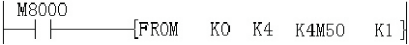
Read the current weighing state BFM4 and judge it by Bit state. For details, please refer to the description of BFM4 in "5.2 Buffer Register Description".
Get the current weighing value
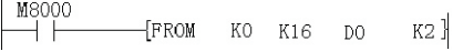
Write the average weight value (BFM16) of CH1 in the weighing module into D0.
Calibration weight
* In the new version, the first step can also be used for manual reset.
The adjustment is to make the module match the weight value of the load cell of the weighing module. The adjustment steps are as follows. Described with CH1.

Tare and gross weight

Filter mode setting
After setting the filter method or filter strength, re-calibration is required.

Zero tracking
Zero tracking is used to reduce temperature drift interference.
The zero tracking range is 0, which means zero tracking is not enabled.

Calibration without weights
The calibration without weights is calibrated by the zero point of the sensor and the maximum range of the sensor. The accuracy is related to the sensor specification and depends on the sensitivity of the sensor (mV/V).
For example: The sensitivity of the LAB-B-B sensor is 2.0±10%mV/V, and there may be a maximum error of 10%. Therefore, it is best to use a sensor with a small sensor sensitivity error when using this function.

Modify calibration parameters

✎Note: BFM35, BFM36, BFM37, and BFM38 are real numbers (float). When inputting, you need to input real numbers. If the input exceeds the range, BFM5 will report an error in writing calibration parameters.
7 Diagnosis
Check
- I. Check that the input wiring and/or extension cables are properly connected to the LX3V-2WT-G analog special function module.
- II. Check that the LX3V system configuration rules are not violated. E.g: The number of special function modules cannot exceed 8, and the total number of system I/O points cannot exceed 256 points.
- Ⅲ. Make sure the correct operating range is selected in the application.
- IV. Check that there is no power overload on the 5V or 24V power supply, remember: the load of the LX3V main unit or active expansion unit varies according to the number of connected modules or special function modules.
- V. Set the LX3V unit in RUN state.
Check errors
If the special function module LX3V-2WT-G does not operate normally, please check the following items.
- Check the status of the LINK indicator
- Blink: Expansion cables are properly connected.
- Otherwise: Check the connection of the extension cable.
- Check the status of the "24V" LED indicator (top right corner of the LX3V-2WT-G)
- Light on LX3V-2WT-G is normal, and 24VDC power is normal.
- Otherwise: 24V DC power supply may be faulty. If the power supply is normal then the LX3V-2WT-G is faulty.
- Check the status of the "COM" LED indicator (top right corner of the LX3V-2WT-G)
- Blink: Numeric conversion works fine.
- Otherwise: Check buffer memory #5 (error status).
If any of the bits (b0, b1, b2) are ON, that's why the COM indicator is off. For details, please refer to "(6) BFM5: Error Code" in "5.2 Buffer Register (BFM) Description" in "Chapter 5" of this manual.
- Check the sensor, measure whether the voltage between S+ and S- is less than (5*sensor sensitivity) mv, the sensor sensitivity is found in the sensor manual used, the unit is (mv/v), if the voltage at this point is out of range, it means the sensor Deformation or wiring errors have occurred. Measure whether the voltage between F+ and F- is 5V, if not, check the sensor wiring.