

LX6V Series
Naming rules
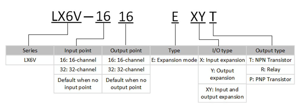
| Model | Description |
| LX6V-0808EXYT | 8-channel switch input and 8-channel transistor output. Input supports NPN or PNP. Output supports NPN. |
| LX6V-16EX | 16-channel switch input; Input supports NPN or PNP. |
| LX6V-16EYT | 16-channel transistor output; Output supports NPN. |
| Model | Function description |
| LX6V-1616EXYT | 16-channel switch input, 16-channel transistor output; Support NPN or PNP input, support NPN output. |
| LX6V-1616EXYP | 16-channel switch input, 16-channel transistor output; Support NPN or PNP input, support PNP output. |
| LX6V-32EYT | 32-channel NPN transistor output; |
| LX6V-32EX | 32-channel switch input; Support NPN or PNP input; |
Device specifications and wiring description
Appearance and size
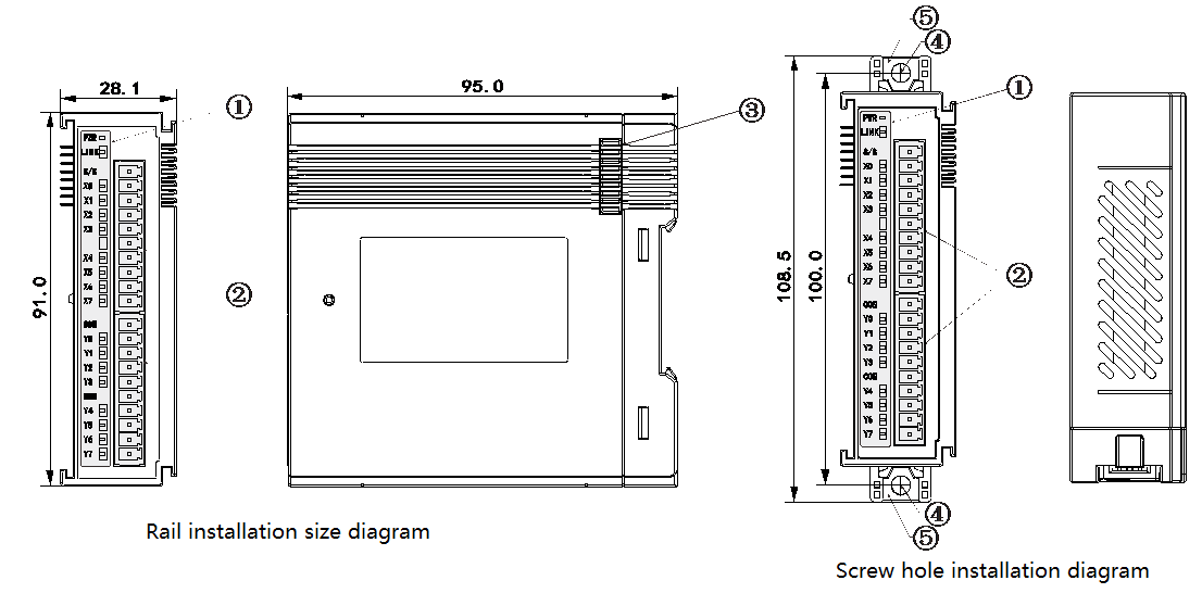
①I/O LED;②I/O terminal;③Expansion module interface; ④Installation hole: 2 (Φ4.5) ;⑤DIN rail fastener
Terminal description
Terminal block arrangement of I/O expansion module as follows:
| Module type | Terminal arrangement |
| LX6V-0808EXYT |  |
| LX6V-16EX |
|
| LX6V-16EYT |
|


Installation
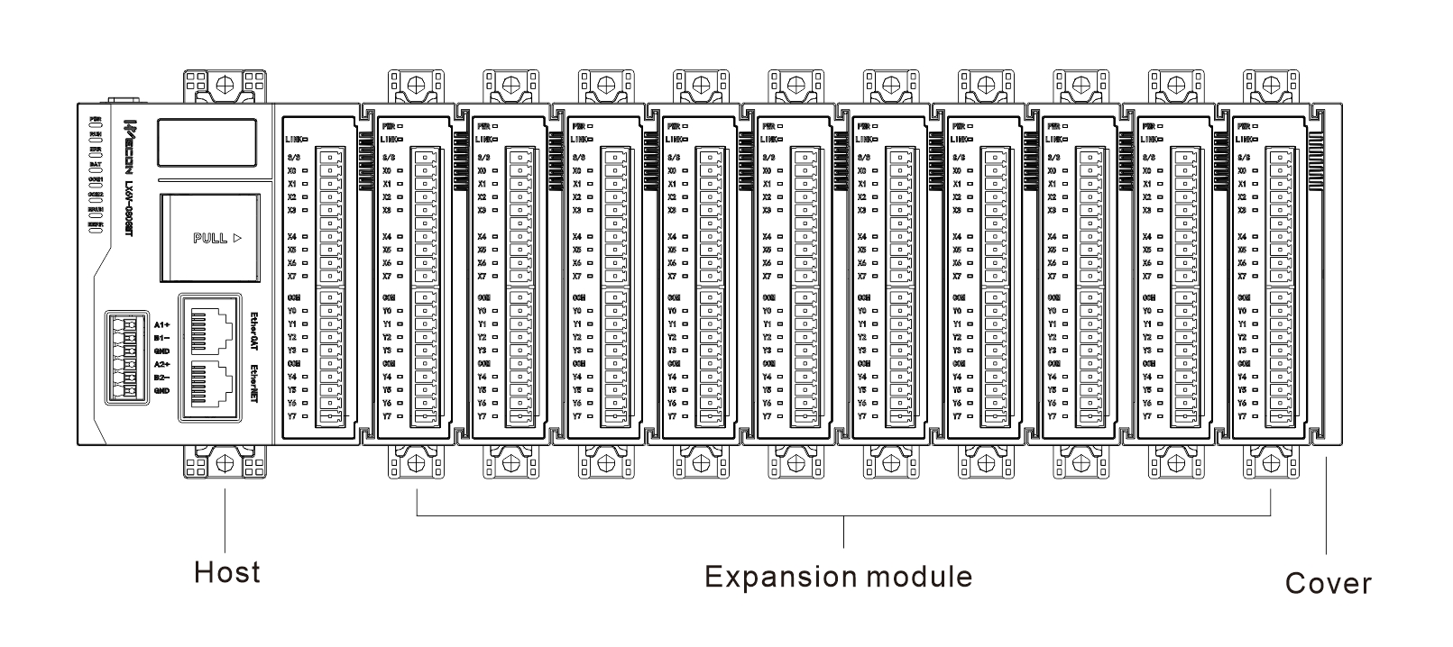
When using, please put the cover at the right side of the last expansion module and align module interface slot to connect it. As shown in the figure below:
Parameter Specification
Input specification
| Project | Digital input |
|---|---|
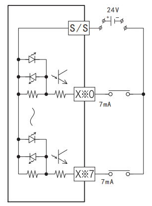
| Input circuit composition |
The figure shows NPN connection. If S/S is connected to 24V negative electrode and X is connected to positive electrode, it is PNP connection. |
| Input signal voltage | DC±24V ±10% |
| Input signal current | 7mA/DC24V (The input current when inputting standard 24V.) |
| Input ON current | Above 3.5 mA |
| Input OFF current | Below 1.5 mA |
| Input response time | About 0.2ms |
| Input signal form | Contact input: support NPN and PNP input |
| Circuit insulation | Transformer isolation |
| Action display | When ON is input, LED lights up. |
Output specification
| Project | Transistor output | ||
|---|---|---|---|
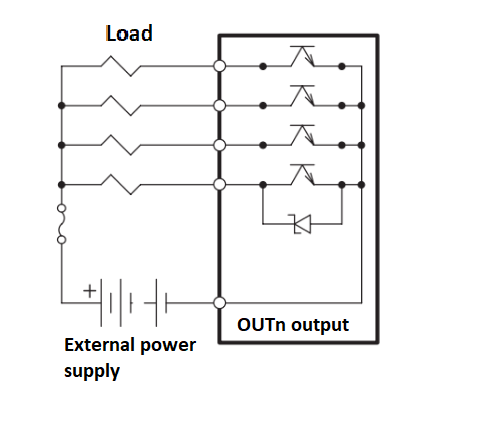
| Output circuit composition |
| ||
| External power supply | DC5~30V | ||
| Circuit insulation | Transformer isolation | ||
| Action display | LED lights up when driving. | ||
Maximum load
| Resistance load | 0.4 A/1 point | |
| Inductive load | 9.6W/DC24V | ||
| Lamp load | 0.9 W/DC24V | ||
| Open circuit leakage current | 0.1 mA/DC30V | ||
| Minimum load | - | ||
Response Time | OFF → ON | About 0.2ms | |
| ON → OFF | About 0.2ms | ||
Environment specification
| Project | Specification requirements |
|---|---|
| Use environment | No corrosive, combustible gas, no large amount of conductive dust (dust) |
| Environment temperature | 0℃~55℃ |
| Environment humidity | 35~85%RH (Non-condensing) |
| Installation | After being installed on the host, it is installed on the rail through a buckle. |
| Overall size | 91*28.1*95mm |
Software specification
Input point:
| Project | Specification requirements |
| Input port filter time | 0ms ~ 64ms (10ms: Default setting), every four X points are one group, and share a group of filter parameters. |
| Input port anomaly detection and indication | None |
| Input channel logic level configuration | No |
| Independent channel enabling configuration | No |
| Diagnostic report configuration | No |
| IO mapping | Support three IO mapping methods: bit access, byte access, word access. |
Output point:
| Project | Specification requirements |
| Output port anomaly detection and indication | None |
| Output channel logic level configuration | No |
| Independent channel enabling configuration | No |
| Diagnostic report configuration | No |
| IO mapping | Support three IO mapping methods: bit access, byte access, word access. |
Instructions
Expansion module configuration process description of upper computer (LX6V-0808EXYT Model as an Example)
① Click on the expansion module configuration to open the configuration interface;
② Adding new modules according to the model and position of the current module connected host;
③ Click the module in the current slot to open the configuration interface;
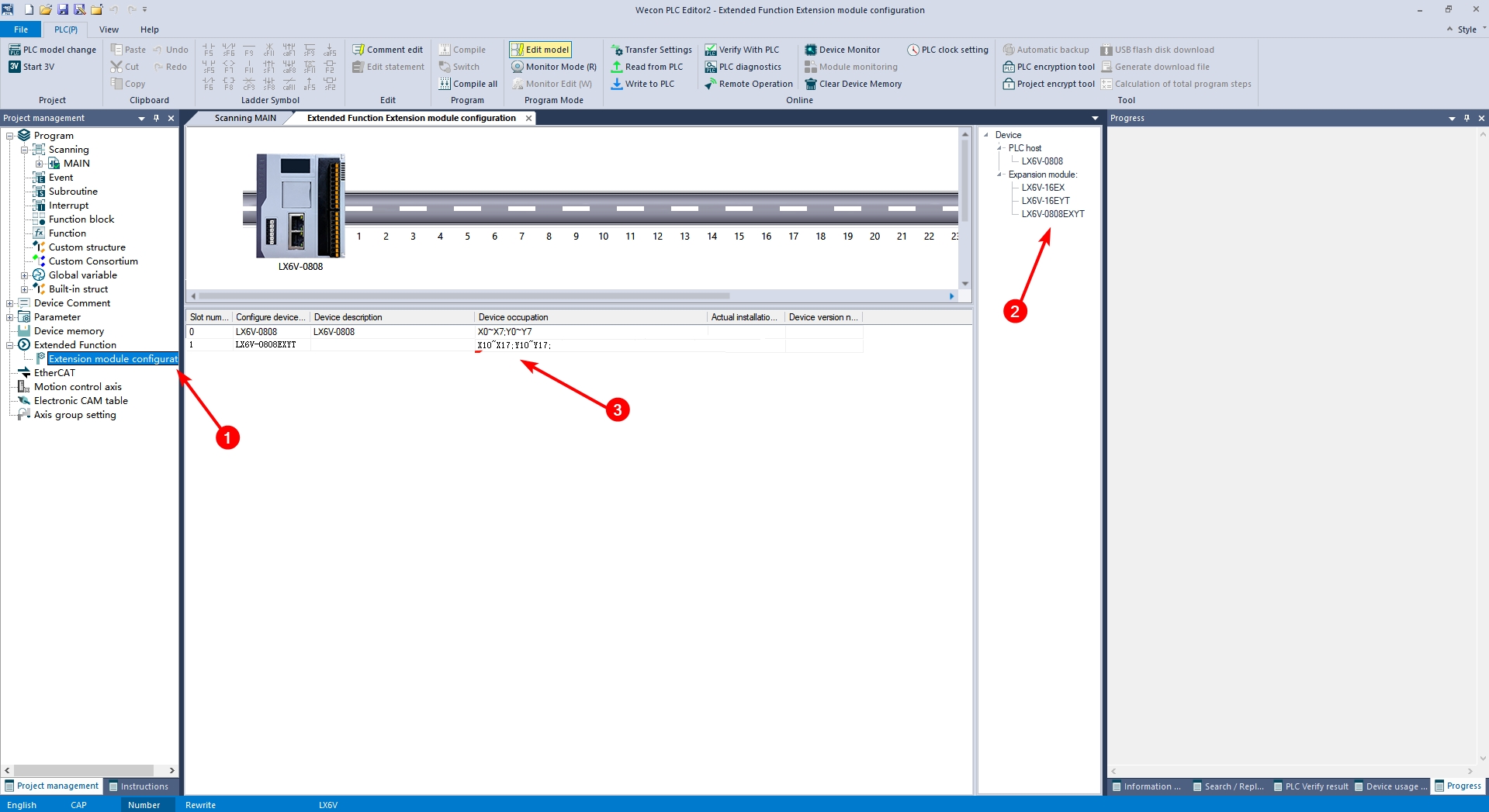
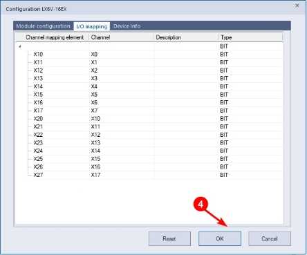
④ Configure module X-point filter time and I/O mapping in turn. Click OK to save the configuration;
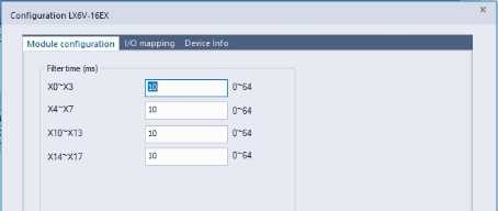
Filter time: The default configuration filter time here is 10ms, and the range: 0ms~64ms
I/O mapping The X and Y points of the module are mapped to X10-X17 and Y10-17 of PLC in turn.
⑤ Click PLC download in turn and check Expansion function. Then click ‘Execute’, and download the expansion module configuration to PLC.
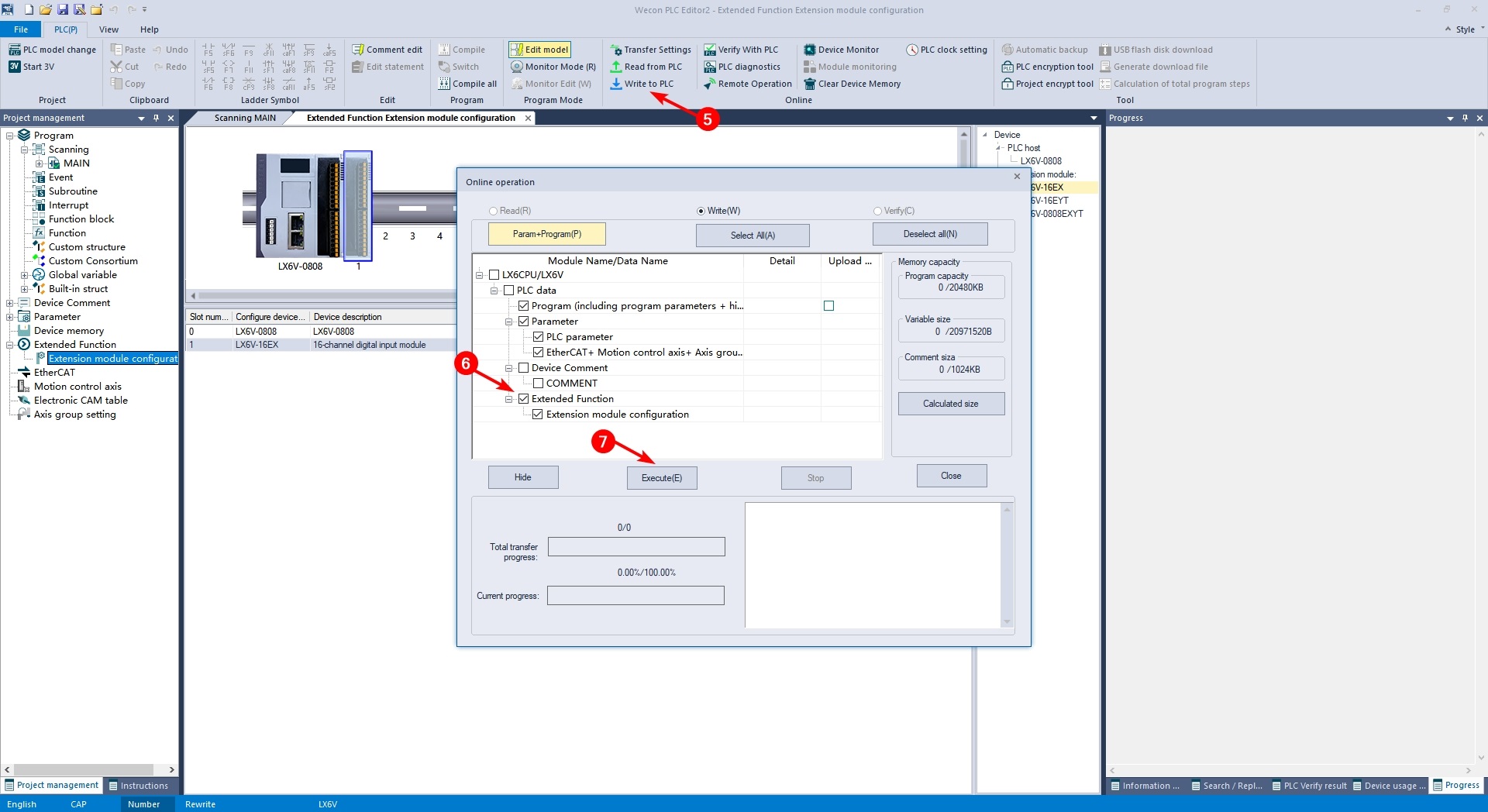
Example
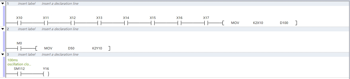
Example description
① After configuring the module and I/O mapping by using the expansion module configuration interface, the X point of the module can be monitored or the Y point state of the module can be set directly through the ladder diagram;
② When M0 is set to ON, Y10~Y17 will be set as the lower 8 bits status of D50;