Transfer Comparison instruction
MOV/16-bit Transmission
MOV(P)
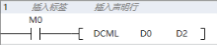
Transfer the BIN 16-bit data of the device specified in (s) to the device specified in (d).
-[MOV (s) (d)]
Content, range and data type
| Parameter | Content | Range | Data type | Data type (label) |
|---|---|---|---|---|
| (s) | Transmit source data or the device number stored data | -32768 to 32767 | Signed BIN16 | ANY16_S |
| (d) | Transmit destination device number | -
| Signed BIN16 | ANY16_S |
Device used
| instruction | Parameter | Devices | Index modification | Pulse extension | |||||||||||||||||||||||
|---|---|---|---|---|---|---|---|---|---|---|---|---|---|---|---|---|---|---|---|---|---|---|---|---|---|---|---|
| X | Y | M | S | SM | T(bit) | C(bit) | LC(bit) | HSC(bit) | D.b | KnX | KnY | KnM | KnS | T | C | D | R | SD | LC | HSC | K | H | E | [D] | XXP | ||
| MOV | Parameter 1 | ● | ● | ● | ● | ● | ● | ● | ● | ● | ● | ● | ● | ● | |||||||||||||
| Parameter 2 | ● | ● | ● | ● | ● | ● | ● | ● | ● | ● | |||||||||||||||||
Features
• Transfer the BIN 16-bit data specified in (s) to the device specified in (d).

Error code
| Error code | Content |
|---|---|
| 4085H | The output result of (s) in read application instruction exceeds the device range |
| 4086H | The output result of (d) in write application instruction exceeds the device range |
Example

When M0 is set, the value of D0 is transferred to the value of D2: (D0)→(D2).
DMOV/32-bit Transmission
DMOV(P)
Transfer the BIN 32-bit data of the device specified in (s) to the device specified in (d).
-[DMOV (s) (d)]
Content, range and data type
| Parameter | Content | Range | Data type | Data type (label) |
|---|---|---|---|---|
| (s) | Transmit source data or the device number stored data | -2147483648 to 2147483647 | Signed BIN32 | ANY32_S |
| (d) | Transmit destination device number | - | Signed BIN32 | ANY32_S |
Device used
| instruction | Parameter | Devices | Index modification | Pulse extension | |||||||||||||||||||||||
|---|---|---|---|---|---|---|---|---|---|---|---|---|---|---|---|---|---|---|---|---|---|---|---|---|---|---|---|
| X | Y | M | S | SM | T(bit) | C(bit) | LC(bit) | HSC(bit) | D.b | KnX | KnY | KnM | KnS | T | C | D | R | SD | LC | HSC | K | H | E | [D] | XXP | ||
| DMOV | Parameter 1 | ● | ● | ● | ● | ● | ● | ● | ● | ● | ● | ● | ● | ● | |||||||||||||
| Parameter 2 | ● | ● | ● | ● | ● | ● | ● | ● | ● | ● | ● | ● | |||||||||||||||
Features
Transfer the BIN 16-bit data specified in (s) to the device specified in (d).
Error code
| Error code | Content |
|---|---|
| 4085H | The output result of (s) in read application instruction exceeds the device range |
| 4086H | The output result of (d) in write application instruction exceeds the device range |
Example

When M0 is set, the value of (D1, D0) is transferred to the value of (D3, D2): (D1, D0) → (D3, D2).
BMOV/Batch Transmission
BMOV(P)
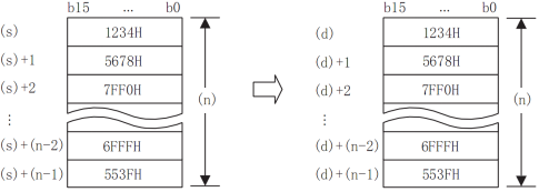
The (n) point BIN 16-bit data starting from the device specified in (s) is sequentially transmitted to the device specified in (d).
-[BMOV (s) (d) (n)]
Content, range and data type
| Parameter | Content | Range | Data type | Data type (label) |
|---|---|---|---|---|
| (s) | The start device that stores the transmission data | - | Signed BIN16 | ANY16_S |
| (d) | The start device that transmit target | - | Signed BIN16 | ANY16_S |
| (n) | Number of transmission | 1 ≤ n ≤ 512 | Signed BIN16 | ANY16_S |
Device used
| instruction | Parameter | Devices | Index modification | Pulse extension | |||||||||||||||||||||||
|---|---|---|---|---|---|---|---|---|---|---|---|---|---|---|---|---|---|---|---|---|---|---|---|---|---|---|---|
| X | Y | M | S | SM | T(bit) | C(bit) | LC(bit) | HSC(bit) | D.b | KnX | KnY | KnM | KnS | T | C | D | R | SD | LC | HSC | K | H | E | [D] | XXP | ||
| BMOV | Parameter 1 | ● | ● | ● | ● | ● | ● | ● | ● | ● | ● | ● | |||||||||||||||
| Parameter 2 | ● | ● | ● | ● | ● | ● | ● | ● | ● | ● | |||||||||||||||||
| Parameter 3 | ● | ● | ● | ● | ● | ● | ● | ● | ● | ● | ● | ● | ● | ||||||||||||||
Features
Batch transfer the BIN 16-bit data of point (n) starting from the device specified in (s) to the device specified in (d).
When the device number exceeds the range, it will be transferred within the allowable range.
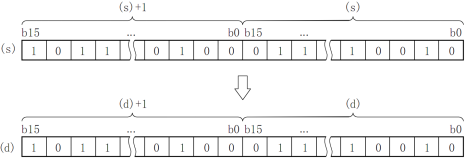
By controlling the direction reversal flag (SM224) of the BMOV instruction, the BIN 16-bit data at point (n) starting from the device specified in (d) can be batch transferred to the device specified in (s).
Error code
| Error code | Content |
|---|---|
| 4084H | In application instruction (n) input the data exceeds the specified range |
| 4085H | The output results of (s) and (n) in read application instruction exceed the device range |
| 4086H | The output result of (d) in write application instruction exceeds the device range |
Example
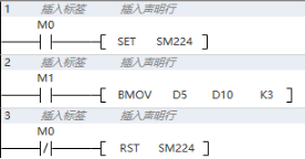
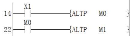
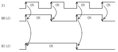
When M0 is set, set M1, then (D5)→(D10); (D6)→(D11); (D7)→(D12);
When M0 is reset, set M1, then (D10)→(D5); (D11)→(D6); (D12)→(D7).
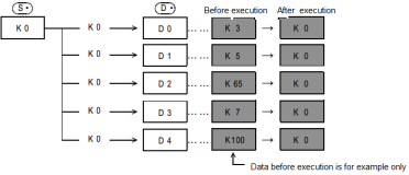
FMOV/16-bit Multicast
FMOV(P)
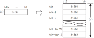
Transfer the BIN 16-bit data of the device specified in (s1) to the device specified in (d) at (n) points (that is, transfer the same data to multiple addresses).
-[FMOV (s) (d) (n)]
Content, range and data type
| Parameter | Content | Range | Data type | Data type (label) |
|---|---|---|---|---|
| (s) | The start device that stores the transmission data | -32768 to 32767 | Signed BIN16 | ANY16_S |
| (d) | The start device that transmit target | - | Signed BIN16 | ANY16_S |
| (n) | Number of transmission | [K1 ≤ n ≤ 512] | Signed BIN16 | ANY16_S |
Device used
| instruction | Parameter | Devices | Index modification | Pulse extension | |||||||||||||||||||||||
|---|---|---|---|---|---|---|---|---|---|---|---|---|---|---|---|---|---|---|---|---|---|---|---|---|---|---|---|
| X | Y | M | S | SM | T(bit) | C(bit) | LC(bit) | HSC(bit) | D.b | KnX | KnY | KnM | KnS | T | C | D | R | SD | LC | HSC | K | H | E | [D] | XXP | ||
| FMOV | Parameter 1 | ● | ● | ● | ● | ● | ● | ● | ● | ● | ● | ● | ● | ● | |||||||||||||
| Parameter 2 | ● | ● | ● | ● | ● | ● | ● | ● | ● | ● | |||||||||||||||||
| Parameter 3 | ● | ● | ● | ● | ● | ● | ● | ● | ● | ● | ● | ● | ● | ||||||||||||||
Features
The same data as the BIN 16-bit data of the device specified in (s) is transferred to the device specified in (d) at (n) points.
When the number specified in (n) exceeds the device number range, transfer is performed within the allowable range.
When a constant (K) is specified for the transmission source (s), it will be automatically converted to BIN.
Error code
| Error code | Content |
|---|---|
| 4084H | (s) and(n) input the data In application instruction exceed the specified range |
| 4085H | The output results of (s) and (n) in read application instruction exceed the device range |
| 4086H | The output result of (d) in write application instruction exceeds the device range |
Example
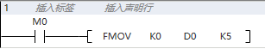
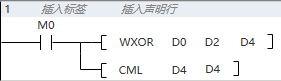
When M0 is set, the value of D0 to D4 is set to 0.
DFMOV/ 32-bit Multicast
DFMOV(P)
Transfer the BIN 32-bit data of the device specified in (s1) to the device specified in (d) at (n) points (that is, transfer the same data to multiple addresses).
-[FMOV (s) (d) (n)]
Content, range and data type
| Parameter | Content | Range | Data type | Data type (label) |
|---|---|---|---|---|
| (s) | Transfer data or start device storing transfer data | -2147483648 to 2147483647 | Signed BIN32 | ANY32_S |
| (d) | Start device of transfer destination | - | Signed BIN32 | ANY32_S |
| (n) | Number of transfers | [1≤n≤512] | Signed BIN32 | ANY32_S |
Device used
| instruction | Parameter | Devices | Index modification | Pulse extension | |||||||||||||||||||||||
|---|---|---|---|---|---|---|---|---|---|---|---|---|---|---|---|---|---|---|---|---|---|---|---|---|---|---|---|
| X | Y | M | S | SM | T(bit) | C(bit) | LC(bit) | HSC(bit) | D.b | KnX | KnY | KnM | KnS | T | C | D | R | SD | LC | HSC | K | H | E | [D] | XXP | ||
| DFMOV | Parameter 1 | ● | ● | ● | ● | ● | ● | ● | ● | ● | ● | ● | ● | ● | ● | ● | |||||||||||
| Parameter 2 | ● | ● | ● | ● | ● | ● | ● | ● | ● | ● | |||||||||||||||||
| Parameter 3 | ● | ● | ● | ● | ● | ● | ● | ● | ● | ● | ● | ● | ● | ||||||||||||||
Features
The same data as the BIN 32-bit data of the device specified in (s) is transferred to the device specified in (d) at (n) points.

When the number specified in (n) exceeds the device number range, transfer is performed within the allowable range.
When a constant (K) is specified for the transmission source (s), it will be automatically converted to BIN.
Error code
| Error code | Content |
|---|---|
| 4084H | (s) and (n) input the data In application instruction exceed the specified range |
| 4085H | The output results of (s) and (n) in read application instruction exceed the device range |
| 4086H | The output result of (d) in write application instruction exceeds the device range |
Example

When M0 is set, the value of (D1, D0), (D3, D2), (D5, D4), (D7, D6), (D9, D8) is set to 0.
SMOV/Bit Shift
SMOV(P)
A instruction for distributing and synthesizing data in units of digits (4 bits).
-[SMOV (s) (n1) (n2) (d) (n3)]
Content, range and data type
| Parameter | Content | Range | Data type | Data type (label) |
|---|---|---|---|---|
| (s) | The word device number that stores the data whose bit is to be moved | Signed BIN16 | ANY16_S | |
| (n1) | Transfer destination device number | 1 to 4 | Signed BIN16 | ANY16_S |
| (n2) | The number of digits to move | 1 to 4 | Signed BIN16 | ANY16_S |
| (d) | The word device number that stores data for bit shifting | Signed BIN16 | ANY16_S | |
| (n3) | The starting position of the moving target | 1 to 4 | Signed BIN16 | ANY16_S |
Device used
| instruction | Parameter | Devices | Index modification | Pulse extension | |||||||||||||||||||||||
|---|---|---|---|---|---|---|---|---|---|---|---|---|---|---|---|---|---|---|---|---|---|---|---|---|---|---|---|
| X | Y | M | S | SM | T(bit) | C(bit) | LC(bit) | HSC(bit) | D.b | KnX | KnY | KnM | KnS | T | C | D | R | SD | LC | HSC | K | H | E | [D] | XXP | ||
| SMOV | Parameter 1 | ● | ● | ● | ● | ● | ● | ● | ● | ● | ● | ● | |||||||||||||||
| Parameter 2 | ● | ● | ● | ● | ● | ● | ● | ● | ● | ● | ● | ● | ● | ||||||||||||||
| Parameter 3 | ● | ● | ● | ● | ● | ● | ● | ● | ● | ● | ● | ● | ● | ||||||||||||||
| Parameter 4 | ● | ● | ● | ● | ● | ● | ● | ● | ● | ● | |||||||||||||||||
| Parameter 5 | ● | ● | ● | ● | ● | ● | ● | ● | ● | ● | ● | ● | ● | ||||||||||||||
Features
destination (d) are conver.The data is distributed/combined in units of digits (4 bits). The contents of the transmission source (s) and the transmission ted into 4-digit BCD (0000 to 9999), and the (n1) bits are transferred to the lower (n2) bits and the (n3) bits of the transmission destination (d) (combined ). After reaching the starting position, it is converted to BIN and stored in the transfer destination (d).
When the instruction input is OFF, the transfer destination (d) does not change.
When the instruction input is ON, the data of the transmission source (s) and the number of digits other than the transmission specification of the transmission destination (d) do not change.
- Perform BIN→BCD conversion on (s).
- Transfer (synthesize) the (n1)th bit to the lower (n2), (d), (n3)th bit to the (n2)th bit counted from the previous. (D), the first and fourth digits start from (s), and the transmission will not be affected.
- Convert the synthesized data (BCD) into BIN and store it in (d).
Extended function
If the SMOV instruction is executed after SM168 is turned ON, the BIN→BCD conversion will not be performed. The bit shift is performed in 4-bit units.
Error code
| Error code | Content |
|---|---|
| 4084H | (n1), (n2) and (n3) input data that exceed the specified range in the application instruction or does not satisfy the relationship of n2≤n1 and n2≤n3. |
| 4085H | The output result of (s), (n1) (n2), (d) and (n3) in the read application instruction exceeds the device range |
| 4086H | The output result of (d) in write application instructions exceeds the device range |
Example
After synthesizing the data of the 3-digit digital switch, it is stored in D2 in binary.

Combine data of 3 digital switches connected to non-continuous input terminals.
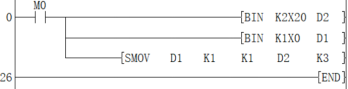
When M0 is set,
(X020 to X027) BCD 2 digits → D 2 (binary);
(X000 to X003) BCD 1 digit → D 1 (binary);
Store the 1 digit of D1 into the 3 digit of D2, and synthesize a 3-digit value.
CML/16-bit Invert Transmission
CML(P)
After the BIN 16-bit data specified in (s) is inverted bit by bit, the result is transferred to the device specified in (d).
-[CML (s) (d)]
Content, range and data type
| Parameter | Content | Range | Data type | Data type (label) |
|---|---|---|---|---|
| (s) | Inverted data or the device number that stores data | -32768 to 32767 | Signed BIN16 | ANY16_S |
| (d) | The device number that stores the inversion result | - | Signed BIN16 | ANY16_S |
Device used
| instruction | Parameter | Devices | Index modification | Pulse extension | |||||||||||||||||||||||
|---|---|---|---|---|---|---|---|---|---|---|---|---|---|---|---|---|---|---|---|---|---|---|---|---|---|---|---|
| X | Y | M | S | SM | T(bit) | C(bit) | LC(bit) | HSC(bit) | D.b | KnX | KnY | KnM | KnS | T | C | D | R | SD | LC | HSC | K | H | E | [D] | XXP | ||
| CML | Parameter 1 | ● | ● | ● | ● | ● | ● | ● | ● | ● | ● | ● | ● | ● | |||||||||||||
| Parameter 2 | ● | ● | ● | ● | ● | ● | ● | ● | ● | ● | |||||||||||||||||
Features
After inverting the BIN 16-bit data specified in (s) bit by bit, the result is transferred to the device specified in (d).

When the number of digits of the device with the specified digit is 4 points, other digits are not affected.
Error code
| Error code | Content |
|---|---|
| 4085H | The output result of (s) in read application instruction exceeds the device range |
| 4086H | The output result of (d) in write application instruction exceeds the device range |
Example
Example 1:
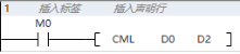
When M0 is set, the value of D0 is inverted and transferred to the value of D2.
Example 2:
invert input acquisition:

DCML/32-bit Invert Transmission
DCML(P)
After the BIN 32-bit data specified in (s) is inverted bit by bit, the result is transferred to the device specified in (d).
-[CML (s) (d)]
Content, range and data type
| Parameter | Content | Range | Data type | Data type (label) |
|---|---|---|---|---|
| (s) | Inverted data or the device number that stores data | -2147483648 to 2147483647 | Signed BIN32 | ANY32_S |
| (d) | The device number that stores the inversion result | - | Signed BIN32 | ANY32_S |
Device used
| instruction | Parameter | Devices | Index modification | Pulse extension | |||||||||||||||||||||||
|---|---|---|---|---|---|---|---|---|---|---|---|---|---|---|---|---|---|---|---|---|---|---|---|---|---|---|---|
| X | Y | M | S | SM | T(bit) | C(bit) | LC(bit) | HSC(bit) | D.b | KnX | KnY | KnM | KnS | T | C | D | R | SD | LC | HSC | K | H | E | [D] | XXP | ||
| DCML | Parameter 1 | ● | ● | ● | ● | ● | ● | ● | ● | ● | ● | ● | ● | ● | ● | ● | |||||||||||
| Parameter 2 | ● | ● | ● | ● | ● | ● | ● | ● | ● | ● | ● | ● | |||||||||||||||
Features
After inverting the BIN 32-bit data specified in (s) bit by bit, the result is transferred to the device specified in (d).

When the number of digits of the device with the specified digit is 4 points, other digits are not affected.
Error code
| Error code | Content |
|---|---|
| 4085H | The output result of (s) in read application instruction exceeds the device range |
| 4086H | The output result of (d) in write application instruction exceeds the device range |
Example
When M0 is set, the value of (D1, D0) is reversed and transferred to the value of (D3, D2).
CMP/16-bit Data Comparison Output
CMP(P)
Compare the BIN 16-bit data of the device specified in (s1) and (s2).
-[CML (s1) (s2) (d)]
Content, range and data type
| Parameter | Content | Range | Data type | Data type (label) |
| (s1) | Comparison value data or the device storing the comparison value data | -32768 to +32767 | Signed BIN16 | ANY16_S |
| (s2) | Comparison source data or the device storing the comparison source data | -32768 to 32767 | Signed BIN16 | ANY16_S |
| (d) | Start bit device for output comparison result | Bit | ANYBIT_ARRAY |
Device used
| instruction | Parameter | Devices | Index modification | Pulse extension | |||||||||||||||||||||||
| X | Y | M | S | SM | T(bit) | C(bit) | LC(bit) | HSC(bit) | D.b | KnX | KnY | KnM | KnS | T | C | D | R | SD | LC | HSC | K | H | E | [D] | XXP | ||
| CMP | Parameter 1 | ● | ● | ● | ● | ● | ● | ● | ● | ● | ● | ● | ● | ● | |||||||||||||
| Parameter 2 | ● | ● | ● | ● | ● | ● | ● | ● | ● | ● | |||||||||||||||||
| Parameter 3 | ● | ● | ● | ● | ● | ● | |||||||||||||||||||||
Features
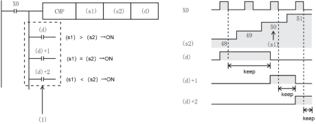
Compare the BIN 16-bit data of the device specified in (s1) with the BIN 16-bit data of the device specified in (s2). According to the result (less than, consistent, greater than), (d), (d)+1, (d) One of )+2 will turn ON.
(s1) and (s2) are handled as BIN values within the above setting data range.
Use algebraic methods for size comparison.
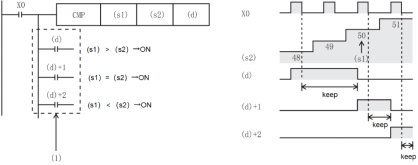
(1): Even if the instruction input is OFF and the CMP instruction is not executed, (d) to (d)+2 will keep the state before the instruction input changed from ON to OFF.
✎Note:
Occupy the device specified in 3 points (d) at the beginning, please be careful not to overlap with the device used for other control.
Error code
| Error code | Content |
| 4085H | The output results of (s1) and (s2) in read application instruction exceed the device range |
| 4086H | The output result of (d) in write application instruction exceeds the device range |
Example
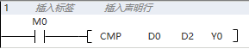
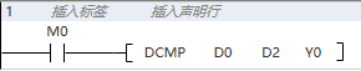
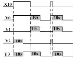
When M0 is set, compare the values of D0 and D2:
If (D0)> (D2) then Y0 is ON.
If (D0) = (D2) then Y1 is ON. If (D0) <(D2) then Y2 is ON.
DCMP/32-bit Data Comparison Output
DCMP(P)
Compare the BIN 32-bit data of the device specified in (s1) and (s2).
-[DCML (s1) (s2) (d)]
Content, range and data type
| Parameter | Content | Range | Data type | Data type (label) |
|---|---|---|---|---|
| (s1) | Comparison value data or the device storing the comparison value data | -2147483648 to 2147483647 | Signed BIN32 | ANY32_S |
| (s2) | Comparison source data or the device storing the comparison source data | -2147483648 to 2147483647 | Signed BIN32 | ANY32_S |
| (d) | Start bit device for output comparison result | Bit | ANYBIT_ARRAY |
Device used
| instruction | Parameter | Devices | Index modification | Pulse extension | |||||||||||||||||||||||
|---|---|---|---|---|---|---|---|---|---|---|---|---|---|---|---|---|---|---|---|---|---|---|---|---|---|---|---|
| X | Y | M | S | SM | T(bit) | C(bit) | LC(bit) | HSC(bit) | D.b | KnX | KnY | KnM | KnS | T | C | D | R | SD | LC | HSC | K | H | E | [D] | XXP | ||
| DCMP | Parameter 1 | ● | ● | ● | ● | ● | ● | ● | ● | ● | ● | ● | ● | ● | ● | ● | |||||||||||
| Parameter 2 | ● | ● | ● | ● | ● | ● | ● | ● | ● | ● | ● | ● | |||||||||||||||
| Parameter 3 | ● | ● | ● | ● | ● | ● | |||||||||||||||||||||
Features
• Compare the BIN 16-bit data of the device specified in (s1) with the BIN 16-bit data of the device specified in (s2). According to the result (less than, consistent, greater than), (d), (d)+1, (d) One of )+2 will turn ON.
• (s1) and (s2) are handled as BIN values within the above setting data range.
• Use algebraic methods for size comparison.
(1): Even if the instruction input is OFF, and the CMP instruction is not executed, (d) to (d)+2 will keep the state before the instruction input changed from ON to OFF.
Error code
| Error code | Content |
|---|---|
| 4085H | The output results of (s1) and (s2) in read application instruction exceed the device range |
| 4086H | The output result of (d) in write application instruction exceeds the device range |
Example

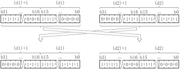
XCH/16-bit Data Exchange
XCH(P)
Exchange the BIN 16-bit data of (d1) and (d2).
-[XCH (d1) (d2)]
Content, range and data type
| Parameter | Content | Range | Data type | Data type (label) |
|---|---|---|---|---|
| (d1) | The start device that stores the exchange data | -32768 to 32767 | Signed BIN16 | ANY16_S |
| (d2) | The start device that stores the exchange data | -32768 to 32767 | Signed BIN16 | ANY16_S |
Device used
| instruction | Parameter | Devices | Index modification | Pulse extension | |||||||||||||||||||||||
|---|---|---|---|---|---|---|---|---|---|---|---|---|---|---|---|---|---|---|---|---|---|---|---|---|---|---|---|
| X | Y | M | S | SM | T(bit) | C(bit) | LC(bit) | HSC(bit) | D.b | KnX | KnY | KnM | KnS | T | C | D | R | SD | LC | HSC | K | H | E | [D] | XXP | ||
| XCH | Parameter 1 | ● | ● | ● | ● | ● | ● | ● | ● | ● | ● | ||||||||||||||||
| Parameter 2 | ● | ● | ● | ● | ● | ● | ● | ● | ● | ● | |||||||||||||||||
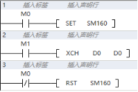
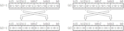
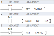
Features
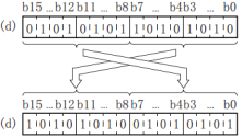
• Exchange the BIN 16-bit data of (d1) and (d2).
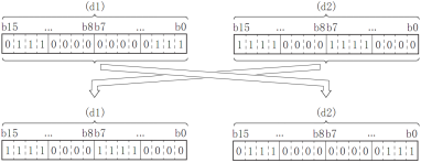
• When executing instructions with SM160 ON, if the device numbers of (d1) and (d2) are the same. Exchange the upper 8 bits (byte) and lower 8 bits (byte) of the word device.
Error code
| Error code | Content |
|---|---|
| 4084H | In exchange mode, the devices in (d1) and (d2) are different |
| 4085H | The output results of (d1) and (d2) in the read application instruction exceed the device range |
| 4086H | The output results of (d1) and (d2) in the writing application instruction exceed the device range |
Example
When M0 is reset, set M1: the value of D0 and the value of D2 are exchanged.

When M0 is set, M1 is set: the upper 8 bits (bytes) and lower 8 bits (bytes) of D0 are exchanged with each other.
DXCH/32-bit Data Exchange
DXCH(P)
Exchange (d1) and (d2) BIN 32-bit data.
-[DXCH (d1) (d2)]
Content, range and data type
| Parameter | Content | Range | Data type | Data type (label) |
|---|---|---|---|---|
| (d1) | The start device that stores the exchange data | -2147483647 to 2147483647 | Signed BIN32 | ANY32_S |
| (d2) | The start device that stores the exchange data | -2147483647 to 2147483647 | Signed BIN32 | ANY32_S |
Device used
| instruction | Parameter | Devices | Index modification | Pulse extension | |||||||||||||||||||||||
|---|---|---|---|---|---|---|---|---|---|---|---|---|---|---|---|---|---|---|---|---|---|---|---|---|---|---|---|
| X | Y | M | S | SM | T(bit) | C(bit) | LC(bit) | HSC(bit) | D.b | KnX | KnY | KnM | KnS | T | C | D | R | SD | LC | HSC | K | H | E | [D] | XXP | ||
| DXCH | Parameter 1 | ● | ● | ● | ● | ● | ● | ● | ● | ● | ● | ● | ● | ||||||||||||||
| Parameter 2 | ● | ● | ● | ● | ● | ● | ● | ● | ● | ● | ● | ● | |||||||||||||||
Features
• Exchange the BIN 32-bit data of (d1), (d1)+1 and (d2), (d2)+1.
• When executing instruction
s with SM160 ON, if the device numbers of (d1) and (d2) are the same. Exchange the upper 8 bits (byte) and lower 8 bits (byte) of the word device (d1) and (d1+1).
Error code
| Error code | Content |
|---|---|
| 4084H | In exchange mode, the devices in (d1) and (d2) are different |
| 4085H | The output results of (d1) and (d2) in the read application instruction exceed the device range |
| 4086H | The output results of (d1) and (d2) in the writing application instruction exceed the device range |
Example :When M0 is set, M1 is set: the high 8 bits (byte) and low 8 bits (byte) of the D0 Devices are exchanged, and the high 8 bits (byte) and low 8 bits (byte) of the D1 Devices) Exchange each other.

When M0 is reset, set M1: the value of (D1, D0) and the value of (D3, D2) are exchanged.
ZCP/16-bit Data Interval Comparison
ZCP(P)
Compare the BIN 16-bit data of the device specified in (s1) and the value (bandwidth) of the BIN 16-bit data of the device specified in (s2) with the BIN 16-bit data of the device specified in the comparison source (s3), Output the result (bottom, area, top) to the device specified in (d) and later.
-[ZCP (s1) (s2) (s3) (d)]
Content, range and data type
| Parameter | Content | Range | Data type | Data type (label) |
|---|---|---|---|---|
| (s1) | The comparison value data of low limit or the device that stores the comparison value data | -32768 to 32767 | Signed BIN16 | ANY16_S |
| (s2) | The comparison value data of high limit or the device that stores the comparison value data | -32768 to 32767 | Signed BIN16 | ANY16_S |
| (s3) | Comparison source data or the device that stores the comparison source data | -32768 to 32767 | Signed BIN16 | ANY16_S |
| (d) | The start bit device of output comparison result | Bit | ANYBIT_ARRAY |
Device used
| instruction | Parameter | Devices | Index modification | Pulse extension | |||||||||||||||||||||||
|---|---|---|---|---|---|---|---|---|---|---|---|---|---|---|---|---|---|---|---|---|---|---|---|---|---|---|---|
| X | Y | M | S | SM | T(bit) | C(bit) | LC(bit) | HSC(bit) | D.b | KnX | KnY | KnM | KnS | T | C | D | R | SD | LC | HSC | K | H | E | [D] | XXP | ||
| ZCP | Parameter 1 | ● | ● | ● | ● | ● | ● | ● | ● | ● | ● | ● | ● | ● | ● | ||||||||||||
| Parameter 2 | ● | ● | ● | ● | ● | ● | ● | ● | ● | ● | ● | ● | ● | ● | |||||||||||||
| Parameter 3 | ● | ● | ● | ● | ● | ● | ● | ● | ● | ● | ● | ● | ● | ● | |||||||||||||
| Parameter 4 | ● | ● | ● | ● | ● | ● | |||||||||||||||||||||
Features
• Compare the BIN 16-bit data of the device specified in (s1) and the value (bandwidth) of the BIN 16-bit data of the device specified in (s2) with the BIN 16-bit data of the device specified in the comparison source (s3) , According to the result (bottom, area, top), one of (d), (d)+1, (d)+2 will be turned ON. (s1), (s2), (s3) are treated as BIN values within the above-mentioned setting data range. Use algebraic methods for size comparison.
• Use algebraic methods for size comparison.

(1): Even if the instruction input is OFF and the ZCP instruction is not executed, (d) to (d)+2 will keep the state before the instruction input turns from ON to OFF.
Error code
| Error code | Content |
|---|---|
| 4085H | The output results of (s1), (s2) and (s3) in the read application instruction exceed the device range |
| 4086H | The output result of (d) in write application instructions exceeds the device range |
Example
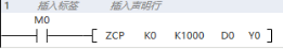
When M0 is set, compare whether D0 is between 0 and 1000:
If (D0)> (1000), then Y0 is ON.
If (0) ≤ (D0) ≤ (1000), then Y1 is ON.
If (D0) <(0), then Y2 is ON.
DZCP/32-bit Data Interval Comparison
DZCP(P)
Compare the BIN 32-bit data of the device specified in (s1) and the value (bandwidth) of the BIN 32-bit data of the device specified in (s2) with the BIN 32-bit data of the device specified in the comparison source (s3), Output the result (bottom, area, top) to the device specified in (d) and later.
-[DZCP (s1) (s2) (s3) (d)]
Content, range and data type
| Parameter | Content | Range | Data type | Data type (label) |
|---|---|---|---|---|
| (s1) | The comparison value data of low limit or the device that stores the comparison value data | -2147483648 to 2147483647 | Signed BIN32 | ANY32_S |
| (s2) | The comparison value data of high limit or the device that stores the comparison value data | -2147483648 to 2147483647 | Signed BIN32 | ANY32_S |
| (s3) | Comparison source data or the device that stores the comparison source data | -2147483648 to 2147483647 | Signed BIN32 | ANY32_S |
| (d) | The start bit device of output comparison result | Bit | ANYBIT_ARRAY |
Device used
| instruction | Parameter | Devices | Index modification | Pulse extension | |||||||||||||||||||||||
|---|---|---|---|---|---|---|---|---|---|---|---|---|---|---|---|---|---|---|---|---|---|---|---|---|---|---|---|
| X | Y | M | S | SM | T(bit) | C(bit) | LC(bit) | HSC(bit) | D.b | KnX | KnY | KnM | KnS | T | C | D | R | SD | LC | HSC | K | H | E | [D] | XXP | ||
| DZCP | Parameter 1 | ● | ● | ● | ● | ● | ● | ● | ● | ● | ● | ● | ● | ● | ● | ● | ● | ||||||||||
| Parameter 2 | ● | ● | ● | ● | ● | ● | ● | ● | ● | ● | ● | ● | ● | ● | ● | ● | |||||||||||
| Parameter 3 | ● | ● | ● | ● | ● | ● | ● | ● | ● | ● | ● | ● | ● | ● | ● | ● | |||||||||||
| Parameter 4 | ● | ● | ● | ● | ● | ● | |||||||||||||||||||||
Features
• Compare the BIN 32-bit data of the device specified in (s1) and the value (bandwidth) of the BIN 32-bit data of the device specified in (s2) with the BIN 32-bit data of the device specified in the comparison source (s3) , According to the result (bottom, area, top), one of (d), (d)+1, (d)+2 will be turned ON. (s1), (s2), (s3) are treated as BIN values within the above-mentioned setting data range. Use algebraic methods for size comparison.
• Use algebraic methods for size comparison.
(1): Even if the instruction input is OFF and the ZCP instruction is not executed, (d) to (d)+2 will keep the state before the instruction input turns from ON to OFF.
Error code
| Error code | Content |
|---|---|
| 4085H | The output results of (s1), (s2) and (s3) in the read application instruction exceed the device range |
| 4086H | The output results of (d) in the write application instruction exceeds the device range |
Example

When M0 is set, compare D0 with whether it is between 0 and 100000:
If (D0)> (100000), then Y0 is ON.
If (0) ≤ (D0) ≤ (100000), then Y1 is ON.
If (D0) <(0), then Y2 is ON.
Cycle Shift instruction
ROR/16-bit Cycle Shift Right
ROR(P)
Shift the 16-bit data of the device specified in (d) to the right by (n) bits without including the carry flag.
-[ROR (d) (n)]
Content, range and data type
| Parameter | Content | Range | Data type | Data type (label) |
|---|---|---|---|---|
| (d) | The device start number for cycle shift right | - | Signed BIN 16 bit | ANY16 |
| (n) | The number of times to cycle shift right | 0 to 15 | Signed BIN 16 bit | ANY16 |
Device used
| instruction | Parameter | Devices | Index modification | Pulse extension | |||||||||||||||||||||||
|---|---|---|---|---|---|---|---|---|---|---|---|---|---|---|---|---|---|---|---|---|---|---|---|---|---|---|---|
| X | Y | M | S | SM | T(bit) | C(bit) | LC(bit) | HSC(bit) | D.b | KnX | KnY | KnM | KnS | T | C | D | R | SD | LC | HSC | K | H | E | [D] | XXP | ||
| ROR | Parameter 1 | ● | ● | ● | ● | ● | ● | ● | ● | ● | ● | ||||||||||||||||
| Parameter 2 | ● | ● | ● | ● | ● | ● | ● | ● | ● | ● | ● | ● | ● | ||||||||||||||
Features
・The 16-bit data of the device specified in (d) is shifted right by (n) bits without including the carry flag. The carry flag is in the ON or OFF state according to the state before the ROR(P) is executed.

(n) Specifies 0 to 15. When a value of 16 or more is specified in (n), the remainder value of (n)÷16 is shifted to the right. For example, when (n)=18, 18÷16=1 and the remainder is 2, so a 2-bit right shift is performed.
Related device
| Device | Name | Content |
|---|---|---|
| SM151 | Carry | It turns ON when the last bit shifted from the lowest is 1. |
Error code
| Error code | Content |
|---|---|
| 4084H | A negative value is specified in (n). |
| 4085H | The output results of (d) and (n) in the read application instruction exceed the device range |
| 4086H | The output result of (d) in the write application instruction exceeds the device range |
Example
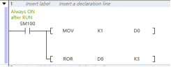
Shift the 1 in the D0 device by 3 bits to the right to get 8192.
DROR/32-bit Cycle Shift Right
DROR(P)
Shift the 32-bit data of the device specified in (d) to the right by (n) bits without including the carry flag.
-[DROR (d) (n)]
Content, range and data type
| Parameter | Content | Range | Data type | Data type (label) |
|---|---|---|---|---|
| (d) | The device start number for cycle shift right | - | Signed BIN 32 bit | ANY32 |
| (n) | The number of times to cycle shift right | 0 to 31 | Signed BIN 32 bit | ANY32 |
Device used
| instruction | Parameter | Devices | Index modification | Pulse extension | |||||||||||||||||||||||
|---|---|---|---|---|---|---|---|---|---|---|---|---|---|---|---|---|---|---|---|---|---|---|---|---|---|---|---|
| X | Y | M | S | SM | T(bit) | C(bit) | LC(bit) | HSC(bit) | D.b | KnX | KnY | KnM | KnS | T | C | D | R | SD | LC | HSC | K | H | E | [D] | XXP | ||
| DROR | Parameter 1 | ● | ● | ● | ● | ● | ● | ● | ● | ● | ● | ● | ● | ||||||||||||||
| Parameter 2 | ● | ● | ● | ● | ● | ● | ● | ● | ● | ● | ● | ● | ● | ● | ● | ||||||||||||
Features
・The 32-bit data of the device specified in (d) is shifted right by (n) bits without including the carry flag. The carry flag is on or off according to the state before DROR(P) is executed.

(n) Specifies 0 to 31. When a value of 32 or more is specified in (n), the remainder of (n)÷32 is shifted to the right. For example, when (n)=34, 34÷32=1 and the remainder is 2, so a 2-bit right shift is performed.
Related device
| Device | Name | Content |
| SM151 | Carry | It turns ON when the last bit shifted from the lowest is 1. |
Error code
| Error code | Content |
|---|---|
| 4084H | A negative value is specified in (n). |
| 4085H | The output results of (d) and (n) in the read application instruction exceed the device range |
| 4086H | The output result of (d) in the write application instruction exceeds the device range |
Example
After the rising edge of M1 is triggered, the value 32 of the D0 device is shifted right by 3 bits to get 4.
RCL/16-bit Cycle Shift Left with Carry
RCL(P)
Shift the 16-bit data of the device specified in (d) to the left by (n) bits with the carry flag included.
-[RCL (d) (n)]
Content, range and data type
| Parameter | Content | Range | Data type | Data type (label) |
|---|---|---|---|---|
| (d) | The device start number for cycle shift left | - | Signed BIN 16 bit | ANY16 |
| (n) | The number of times to cycle shift left | 0 to 15 | Signed BIN 16 bit | ANY16 |
Device used
| instruction | Parameter | Devices | Index modification | Pulse extension | |||||||||||||||||||||||
|---|---|---|---|---|---|---|---|---|---|---|---|---|---|---|---|---|---|---|---|---|---|---|---|---|---|---|---|
| X | Y | M | S | SM | T(bit) | C(bit) | LC(bit) | HSC(bit) | D.b | KnX | KnY | KnM | KnS | T | C | D | R | SD | LC | HSC | K | H | E | [D] | XXP | ||
| RCL | Parameter 1 | ● | ● | ● | ● | ● | ● | ● | ● | ● | ● | ||||||||||||||||
| Parameter 2 | ● | ● | ● | ● | ● | ● | ● | ● | ● | ● | ● | ● | ● | ||||||||||||||
Features
Shift the BIN 16-bit data of the device specified in (d) to the right by (n) bits with the carry flag included. The carry flag is on or off according to the state before the RCR(P) is executed.
(n) Specifies 0 to 15. When a value of 16 or more is specified in (n), the remainder value of (n)÷16 is shifted to the left. For example, when (n)=18, 18÷16=1 and the remainder is 2, so a 2-bit left shift is performed.
Related device
| Device | Name | Content |
|---|---|---|
| SM151 | Carry | It turns ON when the last bit shifted from the highest is 1. |
Error code
| Error code | Content |
|---|---|
| 4084H | A negative value is specified in (n). |
| 4085H | The output results of (d) and (n) in the read application instruction exceed the device range |
| 4086H | The output result of (d) in thewrite application instruction exceeds the device range |
Example
After the rising edge of M0 is triggered, the carry flag SM151 turns ON, and D0 is assigned the value 1.When M1=ON, the value in the D0 device is shifted right by 4 bits to get 12288.
DRCR/32-bit Cycle Shift Right with Carry
DRCR(P)
Shift the 32-bit data of the device specified in (d) to the right by (n) bits with the carry flag included.
-[DRCR (d) (n)]
Content, range and data type
| Parameter | Content | Range | Data type | Data type (label) |
|---|---|---|---|---|
| (d) | The device start number for cycle shift right | - | Signed BIN 32 bit | ANY32 |
| (n) | The number of times to cycle shift right | 0 to 31 | Signed BIN 32 bit | ANY32 |
Device used
| instruction | Parameter | Devices | Index modification | Pulse extension | |||||||||||||||||||||||
|---|---|---|---|---|---|---|---|---|---|---|---|---|---|---|---|---|---|---|---|---|---|---|---|---|---|---|---|
| X | Y | M | S | SM | T(bit) | C(bit) | LC(bit) | HSC(bit) | D.b | KnX | KnY | KnM | KnS | T | C | D | R | SD | LC | HSC | K | H | E | [D] | XXP | ||
| DRCR | Parameter 1 | ● | ● | ● | ● | ● | ● | ● | ● | ● | ● | ● | ● | ||||||||||||||
| Parameter 2 | ● | ● | ● | ● | ● | ● | ● | ● | ● | ● | ● | ● | ● | ● | ● | ||||||||||||
Features
・The BIN 32-bit data of the device specified in (d) is shifted right by (n) bits with the carry flag included. The carry flag is in the ON or OFF state according to the state before DRCR(P) is executed.
(n) Specifies 0 to 31. When a value of 32 or more is specified in (n), the remainder value of (n)÷32 is shifted to the right. For example, when (n)=34, 34÷32=1 and the remainder is 2, so a 2-bit right shift is performed.
Related device
| Devices | Name | Content |
|---|---|---|
| SM151 | Carry | It turns ON when the last bit shifted from the lowest is 1. |
Error code
| Error code | Content |
|---|---|
| 4084H | A negative value is specified in (n). |
| 4085H | The output results of (d) and (n) in the read application instruction exceed the device range |
| 4086H | The output result of (d) in the write application instruction exceeds the device range |
Example
After the rising edge of M0 is triggered, the carry flag SM151 turns ON, and D0 is assigned the value 1. When M1=ON, the value in the D0 device is shifted.
ROL/16-bit Cycle Shift Left
ROL(P)
Shift the 16-bit data of the device specified in (d) to the left by (n) bits without including the carry flag.
-[ROL (d) (n)]
Content, range and data type
| Parameter | Content | Range | Data type | Data type (label) |
|---|---|---|---|---|
| (d) | The device start number for cycle shift left | - | Signed BIN 16 bit | ANY16 |
| (n) | The number of times to cycle shift left | 0 to 15 | Signed BIN 16 bit | ANY16 |
Device used
| instruction | Parameter | Devices | Index modification | Pulse extension | |||||||||||||||||||||||
|---|---|---|---|---|---|---|---|---|---|---|---|---|---|---|---|---|---|---|---|---|---|---|---|---|---|---|---|
| X | Y | M | S | SM | T(bit) | C(bit) | LC(bit) | HSC(bit) | D.b | KnX | KnY | KnM | KnS | T | C | D | R | SD | LC | HSC | K | H | E | [D] | XXP | ||
| ROL | Parameter 1 | ● | ● | ● | ● | ● | ● | ● | ● | ● | ● | ||||||||||||||||
| Parameter 2 | ● | ● | ● | ● | ● | ● | ● | ● | ● | ● | ● | ● | ● | ||||||||||||||
Features
・The 16-bit data of the device specified in (d) is shifted to the left by (n) bits without including the carry flag. The carry flag is in the ON or OFF state according to the state before ROL(P) is executed.
(n) Specify 0 to 15. When a value of 16 or more is specified in (n), the remainder value of (n)÷16 is shifted to the left. For example, when (n)=18, 18÷16=1 and the remainder is 2, so a 2-bit left shift is performed.
Related device
| Device | Name | Content |
|---|---|---|
| SM151 | Carry | It turns ON when the last bit shifted from the highest is 1. |
Error code
| Error code | Content |
|---|---|
| 4084H | A negative value is specified in (n). |
| 4085H | The output results of (d) and (n) in the read application instruction exceed the device range |
| 4086H | The output result of (d) in the write application instruction exceeds the device range |
Example
Shift 1 in the D0 device to the left by 3 bits to get 8.
DROL/32-bit Cycle Shift Left

 DROL(P)
Shift the 32-bit data of the device specified in (d) to the left by (n) bits without including the carry flag.
-[DROL (d) (n)]
Content, range and data type
| Parameter | Content | Range | Data type | Data type (label) |
|---|---|---|---|---|
| (d) | The device start number for cycle shift left | - | Signed BIN 32 bit | ANY32 |
| (n) | The number of times to cycle shift left | 0 to 31 | Signed BIN 32 bit | ANY32 |
Device used
| instruction | Parameter | Devices | Index modification | Pulse extension | |||||||||||||||||||||||
|---|---|---|---|---|---|---|---|---|---|---|---|---|---|---|---|---|---|---|---|---|---|---|---|---|---|---|---|
| X | Y | M | S | SM | T(bit) | C(bit) | LC(bit) | HSC(bit) | D.b | KnX | KnY | KnM | KnS | T | C | D | R | SD | LC | HSC | K | H | E | [D] | XXP | ||
| DROL | Parameter 1 | ● | ● | ● | ● | ● | ● | ● | ● | ● | ● | ● | ● | ||||||||||||||
| Parameter 2 | ● | ● | ● | ● | ● | ● | ● | ● | ● | ● | ● | ● | ● | ● | ● | ||||||||||||
Features
・The 32-bit data of the device specified in (d) is shifted left by (n) bits without including the carry flag. The carry flag is on or off according to the state before DROL(P) is executed.
(n) Specifies 0 to 31. When a value of 32 or more is specified in (n), the remainder of (n)÷32 is shifted to the left. For example, when (n)=34, 34÷32=1 and the remainder is 2, so a 2-bit left shift is performed.
Related device
| Device | Name | Content |
|---|---|---|
| SM151 | Carry | It turns ON when the last bit shifted from the highest is 1. |
Error code
| Error code | Content |
|---|---|
| 4084H | A negative value is specified in (n). |
| 4085H | The output results of (d) and (n) in the read application instruction exceed the device range |
| 4086H | The output result of (d) in the write application instruction exceeds the device range |
Example
Shift 1 in the D0 device to the left by 3 bits to get 8.
RCL/16-bit Cycle Shift Left with Carry
RCL(P)
Shift the 16-bit data of the device specified in (d) to the left by (n) bits with the carry flag included.
-[RCL (d) (n)]
Content, range and data type
| Parameter | Content | Range | Data type | Data type (label) |
|---|---|---|---|---|
| (d) | The device start number for cycle shift left | - | Signed BIN 16 bit | ANY16 |
| (n) | The number of times to cycle shift left | 0 to 15 | Signed BIN 16 bit | ANY16 |
Device used
| instruction | Parameter | Devices | Index modification | Pulse extension | |||||||||||||||||||||||
|---|---|---|---|---|---|---|---|---|---|---|---|---|---|---|---|---|---|---|---|---|---|---|---|---|---|---|---|
| X | Y | M | S | SM | T(bit) | C(bit) | LC(bit) | HSC(bit) | D.b | KnX | KnY | KnM | KnS | T | C | D | R | SD | LC | HSC | K | H | E | [D] | XXP | ||
| RCL | Parameter 1 | ● | ● | ● | ● | ● | ● | ● | ● | ● | ● | ||||||||||||||||
| Parameter 2 | ● | ● | ● | ● | ● | ● | ● | ● | ● | ● | ● | ● | ● | ||||||||||||||
Features
・The 16-bit data of the device specified in (d) is shifted (n) to the left with the carry flag included. The carry flag is on or off according to the state before RCL(P) is executed.
(n) Specifies 0 to 15. When a value of 16 or more is specified in (n), the remainder value of (n)÷16 is shifted to the left. For example, when (n)=18, 18÷16=1 and the remainder is 2, so a 2-bit left shift is performed.
Related device
| Device | Name | Content |
|---|---|---|
| SM151 | Carry | It turns ON when the last bit shifted from the highest is 1. |
✎Note:
Do not set the number of digits (n) shifted to the left to a negative value. In the case of continuous execution type instructions (ROL, RCL), the shift to the left will be executed every scan time (operation cycle), so be careful. When specifying the number of digits to specify the device in (d), only K4 (16-bit instruction) or K8 (32-bit instruction) is valid. (For example, K4Y10, K8M0).
Error code
| Error code | Content |
|---|---|
| 4084H | A negative value is specified in (n). |
| 4085H | The output results of (d) and (n) in the read application instruction exceed the device range |
| 4086H | The output result of (d) in the write application instruction exceeds the device range |
Example

After the rising edge of M0 is triggered, the carry flag SM151 turns ON, and D0 is assigned the value 1.
DRCL/32-bit Cycle Shift Left with Carry
DRCL(P)
Move the 32-bit data of the device specified in (d) to the left by (n) bits with the carry flag included.
-[DRCL (d) (n)]
Content, range and data type
| Parameter | Content | Range | Data type | Data type (label) |
|---|---|---|---|---|
| (d) | The device start number for cycle shift left | - | Signed BIN 32 bit | ANY32 |
| (n) | The number of times to cycle shift left | 0 to 31 | Signed BIN 32 bit | ANY32 |
Device used
| instruction | Parameter | Devices | Index modification | Pulse extension | |||||||||||||||||||||||
|---|---|---|---|---|---|---|---|---|---|---|---|---|---|---|---|---|---|---|---|---|---|---|---|---|---|---|---|
| X | Y | M | S | SM | T(bit) | C(bit) | LC(bit) | HSC(bit) | D.b | KnX | KnY | KnM | KnS | T | C | D | R | SD | LC | HSC | K | H | E | [D] | XXP | ||
| DRCL | Parameter 1 | ● | ● | ● | ● | ● | ● | ● | ● | ● | ● | ● | ● | ||||||||||||||
| Parameter 2 | ● | ● | ● | ● | ● | ● | ● | ● | ● | ● | ● | ● | ● | ● | ● | ||||||||||||
Features
The 32-bit data of the device specified in (d) is shifted (n) to the left with the carry flag included. The carry flag is on or off according to the state before RCL(P) is executed.

(n) Specifies 0 to 31. When a value of 32 or more is specified in (n), the remainder of (n)÷32 is shifted to the left. For example, when (n)=34, 34÷32=1 and the remainder is 2, so a 2-bit left shift is performed.
Related device
| Devices | Name | Content |
|---|---|---|
| SM151 | Carry | Turns ON when the last bit shifted from the highest is 1. |
Error code
| Error code | Content |
|---|---|
| 4084H | A negative value is specified in (n). |
| 4085H | The output results of (d) and (n) in the read application instruction exceed the device range |
| 4086H | The output result of (d) in the write application instruction exceeds the device range |
After the rising edge of M0 is triggered, the carry flag SM151 turns ON, and D0 is assigned the value 1. When M1=ON, carry the value in the D0 device to the left by 4 bits to get 24.
SFTR/n-bit Shift Right of n-bit Data
 SFTR(P)
Shift (n2) the data of the start (n1) bits of the device specified in (d) to the right.
-[SFTR (s) (d) (n1) (n2)]
Content, range and data type
| Parameter | Content | Range | Data type | Data type (label) |
|---|---|---|---|---|
| (s) | The start number of the device storing the shifted data after shifting | - | Bit | ANY_BOOL |
| (d) | The shifted device start number | - | Bit | ANY_BOOL |
| (n1) | The length of shifted data | 0 to 32767 | Signed BIN 16 bit | ANY16 |
| (n2) | Number of shifts | 0 to 32767 | Signed BIN 16 bit | ANY16 |
Device used
| instruction | Parameter | Devices | Index modification | Pulse extension | |||||||||||||||||||||||
|---|---|---|---|---|---|---|---|---|---|---|---|---|---|---|---|---|---|---|---|---|---|---|---|---|---|---|---|
| X | Y | M | S | SM | T(bit) | C(bit) | LC(bit) | HSC(bit) | D.b | KnX | KnY | KnM | KnS | T | C | D | R | SD | LC | HSC | K | H | E | [D] | XXP | ||
| SFTR | Parameter 1 | ● | ● | ● | ● | ● | ● | ● | ● | ||||||||||||||||||
| Parameter 2 | ● | ● | ● | ● | ● | ● | ● | ||||||||||||||||||||
| Parameter 3 | ● | ● | ● | ● | ● | ● | ● | ● | ● | ● | ● | ● | ● | ||||||||||||||
| Parameter 4 | ● | ● | ● | ● | ● | ● | ● | ● | ● | ● | ● | ● | ● | ||||||||||||||
Features
Shift (n2) the data of the start (n1) bits of the device specified in (d) to the right. After shifting, the point (n2) starting from (s) is transferred to the point (n2) starting from (d) + (n1 to n2).
When K0 is specified in (s), the bit of the (d) + (n1 to n2) starting point (n2) after the shift is set to 0.
When K1 is specified in (s), the bit of the (d) + (n1 to n2) starting point (n2) after the shift is set to 1.
(1): When (s)=K0, it becomes 0.
Error code
| Error code | Content |
|---|---|
| 4084H | When the value specified in (n1) and (n2) exceeds the range of 0 to 32767 |
| When the value specified in (n1) and (n2) is (n1)<(n2) | |
| 4085H | When the device specified in read application instructions (s), (d), (n1) and (n2) exceeds the corresponding device range |
| 4086H | When the device specified in the write application instruction (d) exceeds the corresponding device range |
Example
For n1=9 bits (the length of the shift register) data starting with M0, right shift n2=3 bits. After shifting, transfer n2=3 bits from Y0 to n2=3 bits from M6.
SFTL/n-bit Shift Left of n-bit Data
SFTL(P)
Shift the start (n1) bit data of the device specified in (d) to the left by (n2) bits.
-[SFTL (s) (d) (n1) (n2)]
Content, range and data type
| Parameter | Content | Range | Data type | Data type (label) |
|---|---|---|---|---|
| (s) | The start number of the device storing shifted data after shifting | - | Bit | ANY_BOOL |
| (d) | The shifted device start number | - | Bit | ANY_BOOL |
| (n1) | The length of shifted data | 0 to 32767 | Signed BIN 16 bit | ANY16 |
| (n2) | Number of shifts | 0 to 32767 | Signed BIN 16 bit | ANY16 |
Device used
| instruction | Parameter | Devices | Index modification | Pulse extension | |||||||||||||||||||||||
|---|---|---|---|---|---|---|---|---|---|---|---|---|---|---|---|---|---|---|---|---|---|---|---|---|---|---|---|
| X | Y | M | S | SM | T(bit) | C(bit) | LC(bit) | HSC(bit) | D.b | KnX | KnY | KnM | KnS | T | C | D | R | SD | LC | HSC | K | H | E | [D] | XXP | ||
| SFTL | Parameter 1 | ● | ● | ● | ● | ● | ● | ● | ● | ||||||||||||||||||
| Parameter 2 | ● | ● | ● | ● | ● | ● | ● | ||||||||||||||||||||
| Parameter 3 | ● | ● | ● | ● | ● | ● | ● | ● | ● | ● | ● | ● | ● | ||||||||||||||
| Parameter 4 | ● | ● | ● | ● | ● | ● | ● | ● | ● | ● | ● | ● | ● | ||||||||||||||
Features
Shift (n2) bits of the data at the beginning (n1) bits of the device specified in (d). After shifting, the point (n2) starting from (s) is transferred to the point (n2) starting from (d) + (n1 to n2).
When K0 is specified in (s), the bit of the (d) + (n1 to n2) starting point (n2) after the shift is set to 0.
When K1 is specified in (s), the bit of the (d) + (n1 to n2) starting point (n2) after the shift is set to 1.
(1): When (s)=K0, it becomes 0.
Error code
| Error code | Content |
| 4084H | When the value specified in (n1) and (n2) exceeds the range of 0 to 32767 |
| When the value specified in (n1) and (n2) is (n1)<(n2) | |
| 4085H | When the device specified in read application instructions (s), (d), (n1) and (n2) exceeds the corresponding device range |
| 4086H | When the device specified in the write application instruction (d) exceeds the corresponding device range |
Example
WSFR/n-word Shift Right of n-word Data
WSFR(P)
Shift (n2) the data of the start (n1) bits of the device specified in (d) to the right.
-[WSFR (s) (d) (n1) (n2)]
Content, range and data type
| Parameter | Content | Range | Data type | Data type (label) |
|---|---|---|---|---|
| (s) | The start number of the device storing shifted data after shifting | - | word | ANY_BOOL |
| (d) | The shifted device start number | - | word | ANY_BOOL |
| (n1) | The length of shifted data | 0 to 32767 | Signed BIN 16 bit | ANY16 |
| (n2) | Number of shifts | 0 to 32767 | Signed BIN 16 bit | ANY16 |
Device used
| instruction | Parameter | Devices | Index modification | Pulse extension | |||||||||||||||||||||||
|---|---|---|---|---|---|---|---|---|---|---|---|---|---|---|---|---|---|---|---|---|---|---|---|---|---|---|---|
| X | Y | M | S | SM | T(bit) | C(bit) | LC(bit) | HSC(bit) | D.b | KnX | KnY | KnM | KnS | T | C | D | R | SD | LC | HSC | K | H | E | [D] | XXP | ||
| SFTR | Parameter 1 | ● | ● | ● | ● | ● | ● | ● | ● | ● | ● | ● | ● | ● | |||||||||||||
| Parameter 2 | ● | ● | ● | ● | ● | ● | ● | ● | ● | ● | |||||||||||||||||
| Parameter 3 | ● | ● | ● | ● | ● | ● | ● | ● | ● | ● | ● | ● | ● | ||||||||||||||
| Parameter 4 | ● | ● | ● | ● | ● | ● | ● | ● | ● | ● | ● | ● | ● | ||||||||||||||
Features
Shift (n2) the data of the beginning (n1) word of the device specified in (d) to the right. After shifting, the point (n2) starting from (s) is transferred to the point (n2) starting from (d) + (n1 to n2).
When K is specified in (s), the device at (d) + (n1 to n2) starting (n2) point after shifting is set to the specified value.
If the value specified in (n1) or (n2) is 0, it will be no processing.
Error code
| Error code | Content |
|---|---|
| 4084H | When the value specified in (n1) and (n2) exceeds the range of 0 to 32767 |
| When the value specified in (n1) and (n2) is (n1)<(n2) | |
| When (s) and (d) both specify KnM, KnX, and KnS, the value of n varies. | |
| 4085H | When the device specified in read application instructions (s), (d), (n1) and (n2) exceeds the corresponding device range |
| 4086H | When the device specified in the write application instruction (d) exceeds the corresponding device range |
Example

(s) and (d) specify the same multiple in the digit specified device. This program realizes to shift Y0 to Y7 bits right, shift Y10 to Y17 right to Y0 to Y7, and then store X0 to X7 to Y10 to Y17.
WSFL/n-word Shift Left of n-word Data
WSFL(P)
Shift the start (n1) bit data of the device specified in (d) to the left by (n2) bits.
-[WSFL (s) (d) (n1) (n2)]
Content, range and data type
| Parameter | Content | Range | Data type | Data type (label) |
|---|---|---|---|---|
| (s) | The start number of the device storing shifted data after shifting | - | Word | ANY_BOOL |
| (d) | The shifted device start number | - | Word | ANY_BOOL |
| (n1) | The length of shifted data | 0 to 32767 | Signed BIN 16 bit | ANY16 |
| (n2) | Number of shifts | 0 to 32767 | Signed BIN 16 bit | ANY16 |
Device used
| instruction | Parameter | Devices | Index modification | Pulse extension | |||||||||||||||||||||||
|---|---|---|---|---|---|---|---|---|---|---|---|---|---|---|---|---|---|---|---|---|---|---|---|---|---|---|---|
| X | Y | M | S | SM | T(bit) | C(bit) | LC(bit) | HSC(bit) | D.b | KnX | KnY | KnM | KnS | T | C | D | R | SD | LC | HSC | K | H | E | [D] | XXP | ||
| SFTR | Parameter 1 | ● | ● | ● | ● | ● | ● | ● | ● | ● | ● | ● | ● | ● | |||||||||||||
| Parameter 2 | ● | ● | ● | ● | ● | ● | ● | ● | ● | ● | |||||||||||||||||
| Parameter 3 | ● | ● | ● | ● | ● | ● | ● | ● | ● | ● | ● | ● | ● | ||||||||||||||
| Parameter 4 | ● | ● | ● | ● | ● | ● | ● | ● | ● | ● | ● | ● | ● | ||||||||||||||
Features
Shift (n2) the data of the beginning (n1) word of the device specified in (d) to the left. After shifting, transfer the point (n2) starting from (s) to the point (n2) starting from (d).
When K is specified in (s), the device at (d) + (n1 to n2) starting (n2) point after shifting is set to the specified value.
If the value specified in (n1) or (n2) is 0, it will be no processing.
Error Code
| Error code | Content |
|---|---|
| 4084H | When the value specified in (n1) and (n2) exceeds the range of 0 to 32767 |
| When the value specified in (n1) and (n2) is (n1)<(n2) | |
| When (s) and (d) both specify KnM, KnX, and KnS, the value of n varies. | |
| 4085H | When the device specified in read application instructions (s), (d), (n1) and (n2) exceeds the corresponding device range |
| 4086H | When the device specified in the write application instruction (d) exceeds the corresponding device range |
Example
(S), (d) Do the same multiple specification in the digit specification device. This program realizes to remove the high bits of Y10 to Y17 left, move Y0 to Y7 left to Y10 to Y17, and then store X0 to X7 to Y0 to Y7.
SFR/n-bit Shift Right of 16-bit Data
SFR(P)
Shift the 16-bit data of the device specified in (d) right by (n) bits.
-[SFR (d) (n)]
Content, range and data type
| Parameter | Content | Range | Data type | Data type (label) |
|---|---|---|---|---|
| (d) | The start number of the device storing the shifted data | - | Signed BIN 16 bit | ANY16 |
| (n) | Number of shifts | 0-15 | Signed BIN 16 bit | ANY16 |
Device used
| instruction | Parameter | Devices | Index modification | Pulse extension | |||||||||||||||||||||||
|---|---|---|---|---|---|---|---|---|---|---|---|---|---|---|---|---|---|---|---|---|---|---|---|---|---|---|---|
| X | Y | M | S | SM | T(bit) | C(bit) | LC(bit) | HSC(bit) | D.b | KnX | KnY | KnM | KnS | T | C | D | R | SD | LC | HSC | K | H | E | [D] | XXP | ||
| SFR | Parameter 1 | ● | ● | ● | ● | ● | ● | ● | ● | ● | ● | ||||||||||||||||
| Parameter 2 | ● | ● | ● | ● | ● | ● | ● | ● | ● | ● | ● | ● | ● | ||||||||||||||
Features
When (N)=6
Shift the 16-bit data of the device specified in (d) to the right (n) bits from the highest bit. The (n) bit from the most significant bit will become 0.
When (N)=6
When a bit device is specified in (d), the device range specified in the digit specification is shifted to the right.
(n) Specifies 0 to 15. When a value of 16 or more is specified in (n), the remainder of (n)÷16 is shifted to the left. For example, when (n)=18, 18÷16=1 and the remainder 2, so it is shifted by 2 bits to the right.
Related device
| Device | Name | Content |
|---|---|---|
| SM151 | Carry | Set to ON/OFF according to the state of n-1 bit (1/0) |
Error code
| Error code | Content |
|---|---|
| 4084H | A negative value is specified in (n). |
| 4085H | The output results of (d) and (n) in the read application instruction exceed the device range |
| 4086H | The output result of (d) in the write application instruction exceeds the device range |
Example

When M1 is ON, the contents of Y10 to Y23 are shifted to the right by the number of digits specified in D0.
DSFR/n word Data Shift Right by 1 Word
DSFR(P)
Shift the data at the start (n) point of the device specified in (d) to the right by 1 word.
-[DSFR (d) (n)]
Content, range and data type
| Parameter | Content | Range | Data type | Data type (label) |
|---|---|---|---|---|
| (d) | The start number of the device storing the shifted data | - | Signed BIN 16 bit | - |
| (n) | Number of shifts | 0 to 32767 | Signed BIN 16 bit | INT |
Device used
| instruction | Parameter | Devices | Index modification | Pulse extension | |||||||||||||||||||||||
|---|---|---|---|---|---|---|---|---|---|---|---|---|---|---|---|---|---|---|---|---|---|---|---|---|---|---|---|
| X | Y | M | S | SM | T(bit) | C(bit) | LC(bit) | HSC(bit) | D.b | KnX | KnY | KnM | KnS | T | C | D | R | SD | LC | HSC | K | H | E | [D] | XXP | ||
| DSFR | Parameter 1 | ● | ● | ● | ● | ● | ● | ● | ● | ● | ● | ||||||||||||||||
| Parameter 2 | ● | ● | ● | ● | ● | ● | ● | ● | ● | ● | ● | ● | ● | ||||||||||||||
Features
• Shift the data at the start (n) point of the device specified in (d) by 1 word to the right.

• The device specified in (d)+(n-1) will become 0.
Error code
| Error code | Content |
|---|---|
| 4084H | When the value specified in (n) exceeds the range of 0 to 32767 |
| 4085H | The output results of (d) and (n) in the read application instruction exceed the device range |
| 4086H | The output result of (d) in the write application instruction exceeds the device range |
Example
When M1 is ON, shift the contents of D0 to D4 to the right by 1 word (D1→D0, D2→D1, D3→D2, D4→D3, D4 is set to 0).
Before execution:

After execution:
SFL/n-bit Shift Left of 16-bit Data
SFL(P)
Shift the 16-bit data of the device specified in (d) to the left by (n) bits.
-[SFL (d) (n)]
Content, range and data type
| Parameter | Content | Range | Data type | Data type (label) |
|---|---|---|---|---|
| (d) | The start number of the device storing the shifted data | - | Signed BIN 16 bit | ANY16 |
| (n) | Number of shifts | 0 to 15 | Signed BIN 16 bit | ANY16 |
Device used
| instruction | Parameter | Devices | Index modification | Pulse extension | |||||||||||||||||||||||
|---|---|---|---|---|---|---|---|---|---|---|---|---|---|---|---|---|---|---|---|---|---|---|---|---|---|---|---|
| X | Y | M | S | SM | T(bit) | C(bit) | LC(bit) | HSC(bit) | D.b | KnX | KnY | KnM | KnS | T | C | D | R | SD | LC | HSC | K | H | E | [D] | XXP | ||
| SFL | Parameter 1 | ● | ● | ● | ● | ● | ● | ● | ● | ● | ● | ||||||||||||||||
| Parameter 2 | ● | ● | ● | ● | ● | ● | ● | ● | ● | ● | ● | ● | ● | ||||||||||||||
Features
Shift the 16-bit data of the device specified in (d) to the left (n) bits from the lowest bit. The (n) bit from the lowest bit will become 0.
When (n)=8, it is as follows.
When a bit device is specified in (d), the left shift is performed in the device range specified in the digit specification.
When (n)=3, it is as follows.
(n) Specify 0 to 15. When a value of 16 or more is specified in (n), the remainder of (n)÷16 is shifted to the left. For example, when (n)=18, 18÷16=1 remainder 2, so it is shifted by 2 bits to the left.
Related device
| Device | Name | Content |
|---|---|---|
| SM151 | Carry | Turn ON/OFF according to the state of n+1 bit (1/0) |
Error code
| Error code | Content |
|---|---|
| 4084H | A negative value is specified in (n). |
| 4085H | The output results of (d) and (n) in the read application instruction exceed the device range |
| 4086H | The output result of (d) in the write application instruction exceeds the device range |
Example: When M1 is ON, the contents of Y10 to Y17 are shifted to the left by the number of digits specified in D0.
DSFL/one Word Shift Left of n Word Data
DSFL(P)
Move the data at the beginning (n) point of the device specified in (d) by 1 word to the left.
-[DSFL (d) (n)]
Content, range and data type
| Parameter | Content | Range | Data type | Data type (label) |
|---|---|---|---|---|
| (d) | The start number of the device storing the shifted data | - | Signed BIN 16 bit | - |
| (n) | Number of shifts | 0 to 32,767 | Signed BIN 16 bit | INT |
Device used
| instruction | Parameter | Devices | Index modification | Pulse extension | |||||||||||||||||||||||
|---|---|---|---|---|---|---|---|---|---|---|---|---|---|---|---|---|---|---|---|---|---|---|---|---|---|---|---|
| X | Y | M | S | SM | T(bit) | C(bit) | LC(bit) | HSC(bit) | D.b | KnX | KnY | KnM | KnS | T | C | D | R | SD | LC | HSC | K | H | E | [D] | XXP | ||
| DSFL | Parameter 1 | ● | ● | ● | ● | ● | ● | ● | ● | ● | ● | ||||||||||||||||
| Parameter 2 | ● | ● | ● | ● | ● | ● | ● | ● | ● | ● | ● | ● | ● | ||||||||||||||
Features
Shift the data at the start (n) point of the device specified in (d) to the left by 1 word.
The device specified in (d) will become 0.
Error code
| Error code | Content |
| 4084H | When the value specified in (n) exceeds the range of 0 to 32,767 |
| 4085H | The output results of (d) and (n) in the read application instruction exceed the device range |
| 4086H | The output result of (d) in the write application instruction exceeds the device range |
Example
When M1 is ON, shift the contents of D0 to D4 to the left by 1 word (D3→D4, D2→D3, D1→D2, D0→D1, D0 is set to 0).
Before execution:
After execution:
Arithmetic Operation instructions
ADD/16-bit Addition Operation
 ADD(P)
Add the BIN 16-bit data specified in (s1) and the BIN 16-bit data specified in (s2), and store the result in the device specified in (d).
-[ADD (s1) (s2) (d)]
Content, range and data type
| Parameter | Content | Range | Data type | Data type (label) |
|---|---|---|---|---|
| (s1) | Addition operation data or the device storing the addition data | -32768 to 32767 | Signed BIN16 | ANY16_S |
| (s2) | Addition operation data or the device storing the addition data | -32768 to 32767 | Signed BIN16 | ANY16_S |
| (d) | Device for storing operation results | Signed BIN16 | ANY16_S |
Device used
| instruction | Parameter | Devices | Index modification | Pulse extension | |||||||||||||||||||||||
|---|---|---|---|---|---|---|---|---|---|---|---|---|---|---|---|---|---|---|---|---|---|---|---|---|---|---|---|
| X | Y | M | S | SM | T(bit) | C(bit) | LC(bit) | HSC(bit) | D.b | KnX | KnY | KnM | KnS | T | C | D | R | SD | LC | HSC | K | H | E | [D] | XXP | ||
| ADD | Parameter 1 | ● | ● | ● | ● | ● | ● | ● | ● | ● | ● | ● | ● | ● | |||||||||||||
| Parameter 2 | ● | ● | ● | ● | ● | ● | ● | ● | ● | ● | ● | ● | ● | ||||||||||||||
| Parameter 3 | ● | ● | ● | ● | ● | ● | ● | ● | ● | ● | |||||||||||||||||
Features
Add the BIN 16-bit data specified in (s1) and the BIN 16-bit data specified in (s2), and store the result of the addition in the device specified in (d).
Related device
| Devices | Name | Content |
|---|---|---|
| SM151 | Carry | When the operation result exceeds 32,767, the carry flag will be (ON). |
| SM152 | Borrow | When the operation result is less than -32,768, the borrow flag will be (ON). |
| SM153 | Zero point | When the operation result is 0, the zero flag will be (ON). |
| ADD/ADDP/DADD/DADDP instructions | INC/INCP/DINC/DINCP instructions | |||
| sign bit (zero, borrow, carry) | Action | No action | ||
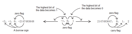
| Calculation result | 16-bit operation result | (S) + (+1) = (d) | 32767 → 0 → +1 → +2 → | 32767→-32768→-32767 |
| (S) + (-1) = (d) | ← -2 ← -1 ← 0 ← -32768 | —— | ||
operation result | (S) + (+1) = (d) | 2147483647 → 0 → +1 → +2 → | 2147483647 → -2147483648→ -2147483647 | |
| (S) + (-1) = (d) | ← -2 ← -1 ← 0 ← -2147483648 | —— | ||
Error code
| Error code | Content |
|---|---|
| 4085H | The output results of (s1) and (s2) in the read application instruction exceed the device range |
| 4086H | The output result of (d) in the write application instruction exceeds the device range |
Example
Add 10 to the data in (D0), and store the operation result in (D2), that is, (D0) + 10 → (D2).
DADD/32-bit Addition Operation
 DADD(P)
Add the BIN32-bit data specified in (s1) and the BIN32-bit data specified in (s2), and store the result in the device specified in (d).
-[DADD (s1) (s2) (d)]
Content, range and data type
| Parameter | Content | Range | Data type | Data type (label) |
|---|---|---|---|---|
| (s1) | Addition data or the device storing the addition data | -2147483648 to 2147483647 | Signed BIN32 | ANY32_S |
| (s2) | Addition data or the device storing the addition data | -2147483648 to 2147483647 | Signed BIN32 | ANY32_S |
| (d) | Device for storing operation results | Signed BIN32 | ANY32_S |
Device used
| instruction | Parameter | Devices | Index modification | Pulse extension | |||||||||||||||||||||||
|---|---|---|---|---|---|---|---|---|---|---|---|---|---|---|---|---|---|---|---|---|---|---|---|---|---|---|---|
| X | Y | M | S | SM | T(bit) | C(bit) | LC(bit) | HSC(bit) | D.b | KnX | KnY | KnM | KnS | T | C | D | R | SD | LC | HSC | K | H | E | [D] | XXP | ||
| DADD | Parameter 1 | ● | ● | ● | ● | ● | ● | ● | ● | ● | ● | ● | ● | ● | ● | ● | |||||||||||
| Parameter 2 | ● | ● | ● | ● | ● | ● | ● | ● | ● | ● | ● | ● | ● | ● | ● | ||||||||||||
| Parameter 3 | ● | ● | ● | ● | ● | ● | ● | ● | ● | ● | |||||||||||||||||
Features
Add the BIN32-bit data specified in (s1) and the BIN32-bit data specified in (s2), and store the result of the addition in the device specified in (d).

Related device
| Devices | Name | Content |
|---|---|---|
| SM151 | Carry | When the operation result exceeds 32,767, the carry flag will be (ON). |
| SM152 | Borrow | When the operation result is less than -32,768, the borrow flag will be (ON). |
| SM153 | Zero point | When the operation result is 0, the zero flag will be (ON). |
| ADD/ADDP/DADD/DADDP instructions | INC/INCP/DINC/DINCP instructions | |||
|---|---|---|---|---|
| sign bit (zero, borrow, carry) | Action | No action | ||
| Calculation result |
Operation result | (S) + (+1) = (d) | 32767→0→+1→+2→ | 32767→-32768→-32767 |
| (S) + (-1) = (d) | ←-2←-1←0←-32768 | —— | ||
operation result | (S) + (+1) = (d) | 2147483647→0→+1→+2→ | 2147483647→-2147483648→-2147483647 | |
| (S) + (-1) = (d) | ←-2←-1←0←-2147483648 | —— | ||
Error code
| Error code | Content |
|---|---|
| 4085H | The output results of (s1) and (s2) in the read application instruction exceed the device range |
| 4086H | The output result of (d) in the write application instruction exceeds the device range |
Example

Add 100000 to the data in (D1, D0), and store the result of the operation in (D3, D2), that is, (D1, D0) + 100000 → (D3, D2).
SUB/16-bit Subtraction Operation
SUB(P)
Subtract the BIN 16-bit data specified in (s1) and the BIN 16-bit data specified in (s2), and store the result in the device specified in (d).
-[SUB (s1) (s2) (d)]
Content, range and data type
| Parameter | Content | Range | Data type | Data type (label) |
| (s1) | The subtraction data or the device storing the subtraction data | -32768 to 32767 | Signed BIN16 | ANY16_S |
| (s2) | The subtraction data or the device storing the subtraction data | -32768 to 32767 | Signed BIN16 | ANY16_S |
| (d) | Device for storing calculation results | Signed BIN16 | ANY16_S |
Device used
| instruction | Parameter | Devices | Index modification | Pulse extension | |||||||||||||||||||||||
|---|---|---|---|---|---|---|---|---|---|---|---|---|---|---|---|---|---|---|---|---|---|---|---|---|---|---|---|
| X | Y | M | S | SM | T(bit) | C(bit) | LC(bit) | HSC(bit) | D.b | KnX | KnY | KnM | KnS | T | C | D | R | SD | LC | HSC | K | H | E | [D] | XXP | ||
| SUB | Parameter 1 | ● | ● | ● | ● | ● | ● | ● | ● | ● | ● | ● | ● | ● | |||||||||||||
| Parameter 2 | ● | ● | ● | ● | ● | ● | ● | ● | ● | ● | ● | ● | ● | ||||||||||||||
| Parameter 3 | ● | ● | ● | ● | ● | ● | ● | ● | ● | ● | |||||||||||||||||
Features
Subtract the BIN 16-bit data specified in (s1) and the BIN 16-bit data specified in (s2), and store the result of the operation in the device specified in (d).
Related device
| Devices | Name | Content |
| SM151 | Carry | When the operation result exceeds 32,767, the carry flag will be (ON). |
| SM152 | Borrow | When the operation result is less than -32,768, the borrow flag will be (ON). |
| SM153 | Zero point | When the operation result is 0, the zero flag will be (ON). |
| SUB/SUBP/DSUB/DSUBP instructions | DEC/DECP/DDEC/DDECP instructions | |||
|---|---|---|---|---|
| Sign bit (zero, borrow, carry) | Action | No action | ||
| Calculation result | 16-bit operation result | (S)-(+1)=(d) | ←-2←-1←0←-32768 | -32768→+32767→32766 |
| (S)-(-1)=(d) | +32767→0→+1→+2→ | —— | ||
| 32-bit operation result | (S)-(+1)=(d) | ←-2←-1←0←-2147483648 | -2147483648→2147483647→2147483646 | |
| (S)-(-1)=(d) | 2147483647→0→+1→+2→ | —— | ||
Error code
| Error code | Content |
|---|---|
| 4085H | The output results of (s1) and (s2) in the read application instruction exceed the device range |
| 4086H | The output result of (d) in the write application instruction exceeds the device range |
Example
Subtract 10 from the data in D0, and store the calculation result in D2, that is, (D0)-10 → (D2).
DSUB/32-bit Subtraction Operation
DSUB(P)
Subtract the BIN32-bit data specified in (s1) and the BIN32-bit data specified in (s2), and store the result in the device specified in (d).
-[DSUB (s1) (s2) (d)]
Content, range and data type
| Parameter | Content | Range | Data type | Data type (label) |
|---|---|---|---|---|
| (s1) | The subtraction data or the device storing the subtraction data | -2147483648 to 2147483647 | Signed BIN32 | ANY32_S |
| (s2) | The subtraction data or the device storing the subtraction data | -2147483648 to 2147483647 | Signed BIN32 | ANY32_S |
| (d) | Device for storing calculation results | Signed BIN32 | ANY32_S |
Device used
| instruction | Parameter | Devices | Index modification | Pulse extension | |||||||||||||||||||||||
|---|---|---|---|---|---|---|---|---|---|---|---|---|---|---|---|---|---|---|---|---|---|---|---|---|---|---|---|
| X | Y | M | S | SM | T(bit) | C(bit) | LC(bit) | HSC(bit) | D.b | KnX | KnY | KnM | KnS | T | C | D | R | SD | LC | HSC | K | H | E | [D] | XXP | ||
| DSUB | Parameter 1 | ● | ● | ● | ● | ● | ● | ● | ● | ● | ● | ● | ● | ● | ● | ● | |||||||||||
| Parameter 2 | ● | ● | ● | ● | ● | ● | ● | ● | ● | ● | ● | ● | ● | ● | ● | ||||||||||||
| Parameter 3 | ● | ● | ● | ● | ● | ● | ● | ● | ● | ● | ● | ● | |||||||||||||||
Features
Subtract the BIN32-bit data specified in (s1) and the BIN32-bit data specified in (s2), and store the result of the operation in the device specified in (d).
Related device
| Devices | Name | Content |
|---|---|---|
| SM151 | Carry | When the operation result exceeds 2,147,483,647, the carry flag will be ON. |
| SM152 | Borrow | When the operation result is less than -2,147,483,648, the borrow flag will be ON. |
| SM153 | Zero point | When the operation result is 0, the zero flag will be ON. |
| SUB/SUBP/DSUB/DSUBP instructions | DEC/DECP/DDEC/DDECP instructions | |||
|---|---|---|---|---|
| Sign bit (zero, borrow, carry) | Action | No action | ||
| Calculation result | 16-bit operation result | (S)-(+1)=(d) | ←-2←-1←0←-32768 | -32768→32767→32766 |
| (S)-(-1)=(d) | +32767→0→+1→+2→ | —— | ||
| 32-bit operation result | (S)-(+1)=(d) | ←-2←-1←0←-2147483648 | -2147483648→2147483647→2147483646 | |
| (S)-(-1)=(d) | +2147483647→0→+1→+2→ | —— | ||
Error code
| Error code | Content |
|---|---|
| 4085H | The output results of (s1) and (s2) in the read application instruction exceed the device range |
| 4086H | The output result of (d) in the write application instruction exceeds the device range |
Example
Subtract 100000 from the data in (D1,D0), and store the result of the operation in (D3,D2), that is, (D1,D0)-10000 → (D3,D2).
MUL/16-bit Multiplication
MUL(P)
Multiply the BIN16 bits specified in (s1) with the BIN16 bits specified in (s2), and store the result in the device specified in (d).
-[MUL (s1) (s2) (d)]
Content, range and data type
| Parameter | Content | Range | Data type | Data type (label) |
|---|---|---|---|---|
| (s1) | Multiplication operation data or the device storing multiplication operation data | -32768 to 32767 | Signed BIN 16 bit | ANY16_S |
| (s2) | Multiplication operation data or the device storing multiplication operation data | -32768 to 32767 | Signed BIN 16 bit | ANY16_S |
| (d) | Device for storing calculation results | Signed BIN 32 bit | ANY32_S |
Device used
| instruction | Parameter | Devices | Index modification | Pulse extension | |||||||||||||||||||||||
|---|---|---|---|---|---|---|---|---|---|---|---|---|---|---|---|---|---|---|---|---|---|---|---|---|---|---|---|
| X | Y | M | S | SM | T(bit) | C(bit) | LC(bit) | HSC(bit) | D.b | KnX | KnY | KnM | KnS | T | C | D | R | SD | LC | HSC | K | H | E | [D] | XXP | ||
| MUL | Parameter 1 | ● | ● | ● | ● | ● | ● | ● | ● | ● | ● | ● | ● | ● | |||||||||||||
| Parameter 2 | ● | ● | ● | ● | ● | ● | ● | ● | ● | ● | ● | ● | ● | ||||||||||||||
| Parameter 3 | ● | ● | ● | ● | ● | ● | ● | ● | ● | ● | ● | ● | |||||||||||||||
Features
Multiply the BIN 16-bit data specified in (s1) with the BIN 16-bit data specified in (s2), and store the result of the operation in the device specified in (d).
(d) is the multiplication result in the case of bit device
• K1: lower 4 bits (b0 to b3)
• K4: Lower 16 bits (b0 to b15)
• K8: Lower 32 bits (b0 to b31)
Error code
| Error code | Content |
| 4085H | The output results of (s1) and (s2) in the read application instruction exceed the device range |
| 4086H | The output result of (d) in the write application instruction exceeds the device range |
Example
Multiply the data in (D0) by (D2), and store the operation result in (D5, D4), that is, (D0) × (D2) → (D5, D4).
DMUL/32-bit Multiplication
DMUL(P)
Multiply the 32-bit BIN specified in (s1) and the 32-bit BIN specified in (s2), and store the result in the device specified in (d).
-[DMUL (s1) (s2) (d)]
Content, range and data type
| Parameter | Content | Range | Data type | Data type (label) |
|---|---|---|---|---|
| (s1) | Multiplication operation data or device storing multiplication operation data | -2147483648 to 2147483647 | Signed BIN 32 bit | ANY32_S |
| (s2) | Multiplication operation data or device storing multiplication operation data | -2147483648 to 2147483647 | Signed BIN 32 bit | ANY32_S |
| (d) | Device for storing calculation results | Signed BIN64 bit | ANY64_S |
Device used
| instruction | Parameter | Devices | Index modification | Pulse extension | |||||||||||||||||||||||
|---|---|---|---|---|---|---|---|---|---|---|---|---|---|---|---|---|---|---|---|---|---|---|---|---|---|---|---|
| X | Y | M | S | SM | T(bit) | C(bit) | LC(bit) | HSC(bit) | D.b | KnX | KnY | KnM | KnS | T | C | D | R | SD | LC | HSC | K | H | E | [D] | XXP | ||
| DMUL | Parameter 1 | ● | ● | ● | ● | ● | ● | ● | ● | ● | ● | ● | ● | ● | ● | ● | |||||||||||
| Parameter 2 | ● | ● | ● | ● | ● | ● | ● | ● | ● | ● | ● | ● | ● | ● | ● | ||||||||||||
| Parameter 3 | ● | ● | ● | ● | ● | ● | ● | ● | ● | ● | ● | ● | |||||||||||||||
Features
Multiply the BIN32-bit data specified in (s1) and the BIN32-bit data specified in (s2), and store the result of the operation in the device specified in (d).
(d) is the multiplication result in the case of bit device
• K1: lower 4 bits (b0 to b3)
• K4: Lower 16 bits (b0 to b15)
• K8: Lower 32 bits (b0 to b31)
Error code
| Error code | Content |
| 4085H | The output results of (s1) and (s2) in the read application instruction exceed the device range |
| 4086H | The output result of (d) in the write application instruction exceeds the device range |
Example
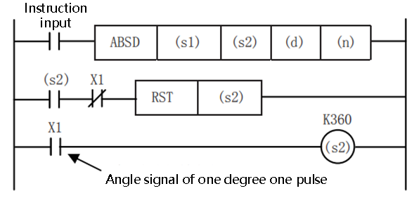
Multiply the data in (D1, D0) by (D3, D2), and store the result of the operation in ((D7, D6), (D5, D4)), ie (D1, D0) × (D3, D2) → ((D7, D6), (D5, D4)).
DIV/16-bit Division Operation
DIV(P)
Divide the BIN 16-bit data specified in (s1) with the BIN 16-bit data specified in (s2), and store the result in the device specified in (d).
-[DIV (s1) (s2) (d)]
Content, range and data type
| Parameter | Content | Range | Data type | Data type (label) |
|---|---|---|---|---|
| (s1) | Division operation data or device storing division operation data | -32768 to 32767 | Signed BIN 16 bit | ANY16_S |
| (s2) | Division operation data or device storing division operation data | -32768 to 32767 | Signed BIN 16 bit | ANY16_S |
| (d) | Device for storing calculation results | Signed BIN 32 bit | ANY32_S |
Device used
| instruction | Parameter | Devices | Index modification | Pulse extension | |||||||||||||||||||||||
|---|---|---|---|---|---|---|---|---|---|---|---|---|---|---|---|---|---|---|---|---|---|---|---|---|---|---|---|
| X | Y | M | S | SM | T(bit) | C(bit) | LC(bit) | HSC(bit) | D.b | KnX | KnY | KnM | KnS | T | C | D | R | SD | LC | HSC | K | H | E | [D] | XXP | ||
| DIV | Parameter 1 | ● | ● | ● | ● | ● | ● | ● | ● | ● | ● | ● | ● | ● | |||||||||||||
| Parameter 2 | ● | ● | ● | ● | ● | ● | ● | ● | ● | ● | ● | ● | ● | ||||||||||||||
| Parameter 3 | ● | ● | ● | ● | ● | ● | ● | ● | ● | ● | ● | ● | |||||||||||||||
Features
Divide the BIN 16-bit data specified in (s1) with the BIN 16-bit data specified in (s2), and store the result of the operation in the device specified in (d).
In the case of a word device, the division result uses a 32-bit storage quotient and remainder, and in the case of a bit device, only a 16-bit storage quotient is used.
• Quotient is stored in the lower 16 bits.
• The remainder is stored in the upper 16 bits. (Can only be stored in the case of word devices.)
Error code
| Error code | Content |
|---|---|
| 4080H | The input of divisor (s2) is 0 |
| 4085H | The output results of (s1) and (s2) in the read application instruction exceed the device range |
| 4086H | The output result of (d) in the write application instruction exceeds the device range |
Example
Divide the data in (D0) by (D2), and store the result of the calculation: the quotient is stored in (D4), and the remainder is stored in (D5), ie (D0)/ (D2) → (D4(quotient)) (D5( remainder)).
DDIV/32-bit Division Operation
 DDIV(P)
Divide the BIN32-bit data specified in (s1) with the BIN32-bit data specified in (s2), and store the result in the device specified in (d).
-[DDIV (s1) (s2) (d)]
Content, range and data type
| Parameter | Content | Range | Data type | Data type (label) |
|---|---|---|---|---|
| (s1) | Division operation data or device storing division operation data | -2147483648 to 2147483647 | Signed BIN 32 bit | ANY32_S |
| (s2) | Division operation data or device storing division operation data | -2147483648 to 2147483647 | Signed BIN 32 bit | ANY32_S |
| (d) | Device for storing calculation results | Signed BIN64 bit | ANY64_S |
Device used
| instruction | Parameter | Devices | Index modification | Pulse extension | |||||||||||||||||||||||
|---|---|---|---|---|---|---|---|---|---|---|---|---|---|---|---|---|---|---|---|---|---|---|---|---|---|---|---|
| X | Y | M | S | SM | T(bit) | C(bit) | LC(bit) | HSC(bit) | D.b | KnX | KnY | KnM | KnS | T | C | D | R | SD | LC | HSC | K | H | E | [D] | XXP | ||
| DDIV | Parameter 1 | ● | ● | ● | ● | ● | ● | ● | ● | ● | ● | ● | ● | ● | ● | ● | |||||||||||
| Parameter 2 | ● | ● | ● | ● | ● | ● | ● | ● | ● | ● | ● | ● | ● | ● | ● | ||||||||||||
| Parameter 3 | ● | ● | ● | ● | ● | ● | ● | ● | ● | ● | ● | ● | |||||||||||||||
Features
Divide the BIN32-bit data specified in (s1) with the BIN32-bit data specified in (s2), and store the result of the operation in the device specified in (d).
In the case of word devices, the division result uses BIN64 bits to store the quotient and remainder. In the case of bit devices, only the BIN 32-bit storage quotient is used.
Error code
| Error code | Content |
|---|---|
| 4080H | The input of divisor (s2) is 0 |
| 4085H | The output results of (s1) and (s2) in the read application instruction exceed the device range |
| 4086H | The output result of (d) in the write application instruction exceeds the device range |
Example
Divide the data in (D1, D0) by (D3, D2), and store the result of the calculation: the quotient is stored in (D5, D4), and the remainder is stored in (D7, D6), that is (D1, D0)/ (D3, D2) → (D5, D4) (quotient) (D7, D6) (remainder).
INC/16-bit Data Increment
INC(P)
Add one to the device (BIN 16-bit data) specified in (d).
-[INC (d)]
Content, range and data type
| Parameter | Content | Range | Data type | Data type (label) |
|---|---|---|---|---|
| (d) | The word device number that stores the data added by one | -32768 to 32767 | Signed BIN 16 bit | ANY16_S |
Device used
| instruction | Parameter | Devices | Index modification | Pulse extension | |||||||||||||||||||||||
|---|---|---|---|---|---|---|---|---|---|---|---|---|---|---|---|---|---|---|---|---|---|---|---|---|---|---|---|
| X | Y | M | S | SM | T(bit) | C(bit) | LC(bit) | HSC(bit) | D.b | KnX | KnY | KnM | KnS | T | C | D | R | SD | LC | HSC | K | H | E | [D] | XXP | ||
| INC | Parameter 1 | ● | ● | ● | ● | ● | ● | ● | ● | ● | ● | ||||||||||||||||
Features
Add one to the device (BIN 16-bit data) specified in (d).
• If the INC(P) instruction is executed when the content of the device specified in (d) is 32767, -32768 will be stored in the device specified in (d).
• Flags (zero, borrow, carry) do not perform actions.
Error code
| Error code | Content |
|---|---|
| 4085H | The output results of (d) in the read application instruction exceed the device range |
| 4086H | The output result of (d) in the write application instruction exceeds the device range |
Example
Add one to the device value specified in D0, that is, (D0) + 1 → (D0).
DINC/32-bit Data Increment
 DINC(P)
Add one to the device (BIN 32-bit data) specified in (d).
-[DINC (d)]
Content, range and data type
| Parameter | Content | Range | Data type | Data type (label) |
|---|---|---|---|---|
| (d) | The word device number that stores the data added by one | -2147483648 to 2147493647 | Signed BIN 32 bit | ANY32_S |
Device used
| instruction | Parameter | Devices | Index modification | Pulse extension | |||||||||||||||||||||||
|---|---|---|---|---|---|---|---|---|---|---|---|---|---|---|---|---|---|---|---|---|---|---|---|---|---|---|---|
| X | Y | M | S | SM | T(bit) | C(bit) | LC(bit) | HSC(bit) | D.b | KnX | KnY | KnM | KnS | T | C | D | R | SD | LC | HSC | K | H | E | [D] | XXP | ||
| DINC | Parameter 1 | ● | ● | ● | ● | ● | ● | ● | ● | ● | ● | ● | ● | ||||||||||||||
Features
Add one to the device (BIN 32-bit data) specified in (d).
• When the DINC(P) instruction is executed when the content of the device specified in (d) is 2147483647, -2147483648 will be stored in the device specified in (d).
• Flags (zero, borrow, carry) do not perform actions.
Error code
| Error code | Content |
|---|---|
| 4085H | The output results of (d) in the read application instruction exceed the device range |
| 4086H | The output result of (d) in the write application instruction exceeds the device range |
Example
Add one to the device value specified in (D1, D0), that is, (D1, D0) + 1 → (D1, D0).
DEC/16 bit Data Decrement
DEC(P)
Minus one for the device (BIN 16-bit data) specified in (d).
-[DEC (d)]
Content, range and data type
| Parameter | Content | Range | Data type | Data type (label) |
|---|---|---|---|---|
| (d) | The word device number that stores the data minus by one | -32768 to 32767 | Signed BIN 16 bit | ANY16_S |
Device used
| instruction | Parameter | Devices | Index modification | Pulse extension | |||||||||||||||||||||||
|---|---|---|---|---|---|---|---|---|---|---|---|---|---|---|---|---|---|---|---|---|---|---|---|---|---|---|---|
| X | Y | M | S | SM | T(bit) | C(bit) | LC(bit) | HSC(bit) | D.b | KnX | KnY | KnM | KnS | T | C | D | R | SD | LC | HSC | K | H | E | [D] | XXP | ||
| DEC | Parameter 1 | ● | ● | ● | ● | ● | ● | ● | ● | ● | ● | ||||||||||||||||
Features
Minus one for the device (BIN 16-bit data) specified in (d).
• If the DEC(P) instruction is executed when the content of the device specified in (d) is -32768, 32767 will be stored in the device specified in (d).
• Flags (zero, borrow, carry) do not perform actions.
Error code
| Error code | Content |
|---|---|
| 4085H | The output results of (d) in the read application instruction exceed the device range |
| 4086H | The output result of (d) in the write application instruction exceeds the device range |
Example
Each time M0 is set, the value of the device specified in D0 will be -1, (D0)-1 → (D0).
DDEC/32-bit Data Decrement
 DDEC(P)
Minus one for the device (BIN 32-bit data) specified in (d).
-[DDEC (d)]
Content, range and data type
| Parameter | Content | Range | Data type | Data type (label) |
|---|---|---|---|---|
| (d) | The word device number that stores the data minus by one | -2147483648 to 2147483647 | Signed BIN 32 bit | ANY32_S |
Device used
| instruction | Parameter | Devices | Index modification | Pulse extension | |||||||||||||||||||||||
|---|---|---|---|---|---|---|---|---|---|---|---|---|---|---|---|---|---|---|---|---|---|---|---|---|---|---|---|
| X | Y | M | S | SM | T(bit) | C(bit) | LC(bit) | HSC(bit) | D.b | KnX | KnY | KnM | KnS | T | C | D | R | SD | LC | HSC | K | H | E | [D] | XXP | ||
| DDEC | Parameter 1 | ● | ● | ● | ● | ● | ● | ● | ● | ● | ● | ● | ● | ||||||||||||||
Features
Minus one for the device (BIN 32-bit data) specified in (d).
If the DDEC(P) instruction is executed when the content of the device specified in (d) is 0, minus one will be stored in the device specified in (d).
• Flags (zero, borrow, carry) do not perform actions.
Error code
| Error code | Content |
|---|---|
| 4085H | The output results of (d) in the read application instruction exceed the device range |
| 4086H | The output result of (d) in the write application instruction exceeds the device range |
Example
Minus one on the device value specified in (D1, D0), that is, (D1, D0)-1 → (D0).
Logic Operation instructions
NEG/16-bit Complement
 NEG(P)
After inverting the sign of the BIN 16-bit device specified in (d), store it in the device specified in (d).
-[NEG (d)]
Content, range and data type
| Parameter | Content | Range | Data type | Data type (label) |
|---|---|---|---|---|
| (d) | The start device that stores the data complement of 2 | -32768 to 32767 | Signed BIN16 | ANY16_S |
Device used
| instruction | Parameter | Devices | Index modification | Pulse extension | |||||||||||||||||||||||
|---|---|---|---|---|---|---|---|---|---|---|---|---|---|---|---|---|---|---|---|---|---|---|---|---|---|---|---|
| X | Y | M | S | SM | T(bit) | C(bit) | LC(bit) | HSC(bit) | D.b | KnX | KnY | KnM | KnS | T | C | D | R | SD | LC | HSC | K | H | E | [D] | XXP | ||
| NEG | Parameter 1 | ● | ● | ● | ● | ● | ● | ● | ● | ● | ● | ● | |||||||||||||||
Features
• Invert the sign of the BIN 16-bit device specified in (d), and store it in the device specified in (d).
• Used when inverting positive and negative signs.
Error code
| Error code | Content |
|---|---|
| 4085H | The output results of (d) in the read application instruction exceed the device range |
| 4086H | The output result of (d) in the write application instruction exceeds the device range |
Example
In the two examples below, if D2=K4 and D4=K8, or D2=K8 and D10 is always K4.
Each time M0 is set, the device value specified in D0 is reversed.
Take the absolute value of the difference of the subtraction operation.
If D2>D4, M10=On. If D2=D4, M11=On. If D2 <D4, M12=On. This ensures that D10 is positive.
It can also be represented by the following program:
When bit15 of D10 is "1" (indicating that D10 is a negative number), M10 = On, use NEG instruction to complement D10 to obtain the absolute value of D10.
In the above two examples, if D2=K4, D4=K8; or D2=K8, D4=K4, the result of D10 is K4.
DNEG/32-bit Complement
DNEG(P)
After inverting the sign of the BIN 32-bit device specified in (d), store it in the device specified in (d).
-[DNEG (d)]
Content, range and data type
| Parameter | Content | Range | Data type | Data type (label) |
|---|---|---|---|---|
| (d) | The start device that stores the data complement of 2 | -2147483648 to 2147483647 | Signed BIN16 | ANY16_S |
Device used
| instruction | Parameter | Devices | Index modification | Pulse extension | |||||||||||||||||||||||
|---|---|---|---|---|---|---|---|---|---|---|---|---|---|---|---|---|---|---|---|---|---|---|---|---|---|---|---|
| X | Y | M | S | SM | T(bit) | C(bit) | LC(bit) | HSC(bit) | D.b | KnX | KnY | KnM | KnS | T | C | D | R | SD | LC | HSC | K | H | E | [D] | XXP | ||
| DNEG | Parameter 1 | ● | ● | ● | ● | ● | ● | ● | ● | ● | ● | ● | ● | ● | |||||||||||||
Features
• Invert the sign of the BIN 32-bit device specified in (d) and store it in the device specified in (d).
• Used when inverting positive and negative signs.
Error code
| Error code | Content |
| 4085H | The output results of (d) in the read application instruction exceed the device range |
| 4086H | The output result of (d) in the write application instruction exceeds the device range |
Example
Each time M0 is set, the device value specified in (D1, D0) is reversed.
WOR/16-bit Data Logical OR
WOR(P)
Perform a logical OR operation on the BIN 16-bit data of the device specified in (s1) and the BIN 16-bit data of the device specified in (s2), and store the result in the device specified in (d).
-[WOR (s1) (s2) (d)]
Content, range and data type
| Parameter | Content | Range | Data type | Data type (label) |
|---|---|---|---|---|
| (s1) | Stores data for logical OR operation or a device that stores data | -32768 to 32767 | Signed BIN16 | ANY16_S |
| (s2) | Stores data for logical OR operation or a device that stores data | -32768to 32767 | Signed BIN16 | ANY16_S |
| (d) | Device for storing logic or result | Signed BIN16 | ANY16_S |
Device used
| instruction | Parameter | Devices | Index modification | Pulse extension | |||||||||||||||||||||||
|---|---|---|---|---|---|---|---|---|---|---|---|---|---|---|---|---|---|---|---|---|---|---|---|---|---|---|---|
| X | Y | M | S | SM | T(bit) | C(bit) | LC(bit) | HSC(bit) | D.b | KnX | KnY | KnM | KnS | T | C | D | R | SD | LC | HSC | K | H | E | [D] | XXP | ||
| WOR | Parameter 1 | ● | ● | ● | ● | ● | ● | ● | ● | ● | ● | ● | ● | ● | |||||||||||||
| Parameter 2 | ● | ● | ● | ● | ● | ● | ● | ● | ● | ● | ● | ● | ● | ||||||||||||||
| Parameter 3 | ● | ● | ● | ● | ● | ● | ● | ● | ● | ● | |||||||||||||||||
Features
• Perform a logical OR operation on the BIN 16-bit data of the device specified in (s1) and the BIN 16-bit data of the device specified in (s2), and store the result in the device specified in (d).
In the case of bit devices, bit devices after the number of points specified by the number of digits will be calculated as 0.
Error code
| Error code | Content |
|---|---|
| 4085H | The output results of (s1) and (s2) in the read application instruction exceed the device range |
| 4086H | The output result of (d) in the write application instruction exceeds the device range |
Example
When M0 is set, (D0) and (D2) are logically performed, and the value is stored in (D4), that is (D0)∨(D2) → (D4)
DOR/32-bit Data Logical OR
 DOR(P)
After inverting the sign of the BIN 32-bit device specified in (d), store it in the device specified in (d).
-[DOR (s1) (s2) (d)]
Content, range and data type
| Parameter | Content | Range | Data type | Data type (label) |
|---|---|---|---|---|
| (s1) | Stores data for logical OR operation or a device that stores data | -2147483648 to 2147483647 | Signed BIN32 | ANY32_S |
| (s2) | Stores data for logical OR operation or a device that stores data | -2147483648 to 2147483647 | Signed BIN32 | ANY32_S |
| (d) | Device for storing logic or result | Signed BIN32 | ANY32_S |
Device used
| instruction | Parameter | Devices | Index modification | Pulse extension | |||||||||||||||||||||||
|---|---|---|---|---|---|---|---|---|---|---|---|---|---|---|---|---|---|---|---|---|---|---|---|---|---|---|---|
| X | Y | M | S | SM | T(bit) | C(bit) | LC(bit) | HSC(bit) | D.b | KnX | KnY | KnM | KnS | T | C | D | R | SD | LC | HSC | K | H | E | [D] | XXP | ||
| DOR | Parameter 1 | ● | ● | ● | ● | ● | ● | ● | ● | ● | ● | ● | ● | ● | ● | ● | |||||||||||
| Parameter 2 | ● | ● | ● | ● | ● | ● | ● | ● | ● | ● | ● | ● | ● | ● | ● | ||||||||||||
| Parameter 3 | ● | ● | ● | ● | ● | ● | ● | ● | ● | ● | ● | ● | |||||||||||||||
Features
Perform a logical OR operation on the BIN 32-bit data of the device specified in (s1) and the BIN 32-bit data of the device specified in (s2), and store the result in the device specified in (d).
In the case of bit devices, bit devices after the number of points specified by the number of digits will be calculated as 0.
Error code
| Error code | Content |
|---|---|
| 4085H | The output results of (s1) and (s2) in the read application instruction exceed the device range |
| 4086H | The output result of (d) in the write application instruction exceeds the device range |
Example
When M0 is set, (D1, D0) and (D3, D2) are logically performed, and the value is stored in (D5, D4), that is, (D1, D0)∨(D3, D2) → (D5, D4) ).
WAND/16-bit Data Logic AND
WAND(P)
Perform a logical AND operation on each bit of the BIN 16-bit data of the device specified in (s1) and the BIN 16-bit data of the device specified in (s2), and store the result in the device specified in (d).
-[WAND (s1) (s2) (d)]
Content, range and data type
| Parameter | Content | Range | Data type | Data type (label) |
|---|---|---|---|---|
| (s1) | Store the data for logical AND operation or the device storing the data | -32768to 32767 | Signed BIN16 | ANY16_S |
| (s2) | Store the data for logical AND operation or the device storing the data | -32768 to 32767 | Signed BIN16 | ANY16_S |
| (d) | Device for storing logic and result | Signed BIN16 | ANY16_S |
Device used
| instruction | Parameter | Devices | Index modification | Pulse extension | |||||||||||||||||||||||
|---|---|---|---|---|---|---|---|---|---|---|---|---|---|---|---|---|---|---|---|---|---|---|---|---|---|---|---|
| X | Y | M | S | SM | T(bit) | C(bit) | LC(bit) | HSC(bit) | D.b | KnX | KnY | KnM | KnS | T | C | D | R | SD | LC | HSC | K | H | E | [D] | XXP | ||
| WAND | Parameter 1 | ● | ● | ● | ● | ● | ● | ● | ● | ● | ● | ● | ● | ● | |||||||||||||
| Parameter 2 | ● | ● | ● | ● | ● | ● | ● | ● | ● | ● | ● | ● | ● | ||||||||||||||
| Parameter 3 | ● | ● | ● | ● | ● | ● | ● | ● | ● | ● | |||||||||||||||||
Features
Perform a logical AND operation on each bit of the BIN 16-bit data of the device specified in (s1) and the BIN 16-bit data of the device specified in (s2), and store the result in the device specified in (d).
In the case of bit devices, bit devices after the number of points specified by the number of digits will be calculated as 0.
Error code
| Error code | Content |
|---|---|
| 4085H | The output results of (s1) and (s2) in the read application instruction exceed the device range |
| 4086H | The output result of (d) in the write application instruction exceeds the device range |
Example
When M0 is set, the logical AND operation of (D0) and (D2) is performed, and the value is stored in (D4), that is, (D0) ∧ (D2) → (D4).
DAND/32-bit Data Logic AND
DAND(P)
Perform a logical AND operation on each bit of the BIN 32-bit data of the device specified in (s1) and the BIN 32-bit data of the device specified in (s2), and store the result in the device specified in (d).
-[DAND (s1) (s2) (d)]
Content, range and data type
| Parameter | Content | Range | Data type | Data type (label) |
|---|---|---|---|---|
| (s1) | Store the data for logical AND operation or the device storing the data | -2147483648 to +2147483647 | Signed BIN32 | ANY32_S |
| (s2) | Store the data for logical AND operation or the device storing the data | -2147483648 to +2147483647 | Signed BIN32 | ANY32_S |
| (d) | Device for storing logic and result | Signed BIN32 | ANY32_S |
Device used
| instruction | Parameter | Devices | Index modification | Pulse extension | |||||||||||||||||||||||
|---|---|---|---|---|---|---|---|---|---|---|---|---|---|---|---|---|---|---|---|---|---|---|---|---|---|---|---|
| X | Y | M | S | SM | T(bit) | C(bit) | LC(bit) | HSC(bit) | D.b | KnX | KnY | KnM | KnS | T | C | D | R | SD | LC | HSC | K | H | E | [D] | XXP | ||
| DAND | Parameter 1 | ● | ● | ● | ● | ● | ● | ● | ● | ● | ● | ● | ● | ● | ● | ● | |||||||||||
| Parameter 2 | ● | ● | ● | ● | ● | ● | ● | ● | ● | ● | ● | ● | ● | ● | ● | ||||||||||||
| Parameter 3 | ● | ● | ● | ● | ● | ● | ● | ● | ● | ● | ● | ● | |||||||||||||||
Features
Perform a logical AND operation on each bit of the BIN 32-bit data of the device specified in (s1) and the BIN 32-bit data of the device specified in (s2), and store the result in the device specified in (d).
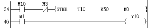
In the case of bit devices, bit devices after the number of points specified by the number of digits will be calculated as 0.
Error code
| Error code | Content |
|---|---|
| 4085H | The output results of (s1) and (s2) in the read application instruction exceed the device range |
| 4086H | The output result of (d) in the write application instruction exceeds the device range |
Example
When M0 is set, perform logical AND operation of (D1, D0) and (D3, D2), and store the value in (D5, D4), (D1, D0) ∧ (D3, D2) → (D5, D4) .
WXOR/16-bit Data Logic Exclusive OR
WXOR(P)
Perform an exclusive OR operation on the BIN 16-bit data of the device specified in (s1) and the BIN 16-bit data of the device specified in (s2), and store the result in the device specified in (d).
-[WXOR (s1) (s2) (d)]
Content, range and data type
| Parameter | Content | Range | Data type | Data type (label) |
|---|---|---|---|---|
| (s1) | Store the data for exclusive OR operation or the device storing the data | -32768 to 32767 | Signed BIN16 | ANY16_S |
| (s2) | Store the data for exclusive OR operation or the device storing the data | -32768 to +32767 | Signed BIN16 | ANY16_S |
| (d) | Device for storing XOR result | Signed BIN16 | ANY16_S |
Device used
| instruction | Parameter | Devices | Index modification | Pulse extension | |||||||||||||||||||||||
|---|---|---|---|---|---|---|---|---|---|---|---|---|---|---|---|---|---|---|---|---|---|---|---|---|---|---|---|
| X | Y | M | S | SM | T(bit) | C(bit) | LC(bit) | HSC(bit) | D.b | KnX | KnY | KnM | KnS | T | C | D | R | SD | LC | HSC | K | H | E | [D] | XXP | ||
| WXOR | Parameter 1 | ● | ● | ● | ● | ● | ● | ● | ● | ● | ● | ● | ● | ● | |||||||||||||
| Parameter 2 | ● | ● | ● | ● | ● | ● | ● | ● | ● | ● | ● | ● | ● | ||||||||||||||
| Parameter 3 | ● | ● | ● | ● | ● | ● | ● | ● | ● | ● | |||||||||||||||||
Features
• Perform logical exclusive OR operation on the BIN 16-bit data of the device specified in (s1) and the BIN 16-bit data of the device specified in (s2), and store the result in the device specified in (d).
In the case of bit devices, bit devices after the number of points specified by the number of digits will be calculated as 0.
Error code
| Error code | Content |
|---|---|
| 4085H | The output results of (s1) and (s2) in the read application instruction exceed the device range |
| 4086H | The output result of (d) in the write application instruction exceeds the device range |
Example
Example 1: When M0 is set, (D0) and (D2) are XOR operation, and the value is stored in (D4), (D0)∀(D2)→(D4).
Example 2: When used with the CML instruction, it can realize the logic exclusive OR (XORNOT) operation:
DXOR/32-bit data logic exclusive OR
DXOR(P)
Perform an exclusive OR operation on the BIN 32-bit data of the device specified in (s1) and the BIN 32-bit data of the device specified in (s2), and store the result in the device specified in (d).
-[DXOR (s1) (s2) (d)]
Content, range and data type
| Parameter | Content | Range | Data type | Data type (label) |
|---|---|---|---|---|
| (s1) | Store the data for exclusive OR operation or the device storing the data | -2147483648 to 2147483647 | Signed BIN32 | ANY32_S |
| (s2) | Store the data for exclusive OR operation or the device storing the data | -2147483648 to 2147483647 | Signed BIN32 | ANY32_S |
| (d) | Device for storing XOR result | Signed BIN32 | ANY32_S |
Device used
| instruction | Parameter | Devices | Index modification | Pulse extension | |||||||||||||||||||||||
|---|---|---|---|---|---|---|---|---|---|---|---|---|---|---|---|---|---|---|---|---|---|---|---|---|---|---|---|
| X | Y | M | S | SM | T(bit) | C(bit) | LC(bit) | HSC(bit) | D.b | KnX | KnY | KnM | KnS | T | C | D | R | SD | LC | HSC | K | H | E | [D] | XXP | ||
| DXOR | Parameter 1 | ● | ● | ● | ● | ● | ● | ● | ● | ● | ● | ● | ● | ● | ● | ● | |||||||||||
| Parameter 2 | ● | ● | ● | ● | ● | ● | ● | ● | ● | ● | ● | ● | ● | ● | ● | ||||||||||||
| Parameter 3 | ● | ● | ● | ● | ● | ● | ● | ● | ● | ● | ● | ● | |||||||||||||||
Features
Perform an exclusive OR operation on the BIN 32-bit data of the device specified in (s1) and the BIN 32-bit data of the device specified in (s2), and store the result in the device specified in (d).
In the case of bit devices, bit devices after the number of points specified by the number of digits will be calculated as 0.
Error code
| Error code | Content |
|---|---|
| 4085H | The output results of (s1) and (s2)in the read application instruction exceed the device range |
| 4086H | The output result of (d) in the write application instruction exceeds the device range |
Example
When M0 is set, (D1, D0) and (D3, D2) are XOR operation, and the value is stored in (D5, D4), that is, (D1, D0) ∀ (D3, D2) → (D5, D4) )
ANS/Alarm Settings
ANS(P)
Used to set alarm instructions.
-[ANS (s) (n) (d)]
Content, range and data type
| Parameter | Content | Range | Data type | Data type (label) |
|---|---|---|---|---|
| (s) | Timer number for judging time | - | Signed BIN 16 bit | ANY16 |
| (n) | Data that judges time | 1 to 32767 | Signed BIN 16 bit | ANY16 |
| (d) | The set alarm device | - | Bit | ANY16_BOOL |
Device used
| instruction | Parameter | Devices | Index modification | Pulse extension | |||||||||||||||||||||||
|---|---|---|---|---|---|---|---|---|---|---|---|---|---|---|---|---|---|---|---|---|---|---|---|---|---|---|---|
| X | Y | M | S | SM | T(bit) | C(bit) | LC(bit) | HSC(bit) | D.b | KnX | KnY | KnM | KnS | T | C | D | R | SD | LC | HSC | K | H | E | [D] | XXP | ||
| ANS | Parameter 1 | ● | ● | ● | |||||||||||||||||||||||
| Parameter 2 | ● | ● | ● | ● | ● | ● | ● | ● | ● | ● | ● | ● | ● | ||||||||||||||
| Parameter 3 | ● | ● | ● | ||||||||||||||||||||||||
Features
When the instruction input continues to be ON for the judgment time [(n)×100ms, timer (s)], set (d). If the instruction time turns off below the judgment time [(n)×100ms], the current value of the judgment timer (s) is reset, and (d) is not set. In addition, if the instruction input turns off, the judgment timer will be reset.
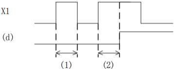
- Judge the time ((n)X 100ms or less)
- Judgment time or more (inclusive) ((n) X 100ms or more (inclusive))
Related device
| Devices | Name | Content |
|---|---|---|
| SM249 | Signal alarm is valid | After SM249 is ON, the following SM248 and SD249 act. |
| SM248 | Signal alarm action | SM249 is ON, when any one of the states S900 to S999 is active, SM248 is ON |
| SD249 | Signal alarm ON state minimum number | Save the smallest number of actions in S900 to S999. |
Error code
| Error code | Content |
|---|---|
| 4084H | The value specified in (n1) and (n2) exceeds the range of 0 to 32767 |
| The timer number is not in the range of T0 to T199. | |
| The signal alarm is not in the range of S900 to S999. | |
| 4085H | When the device specified in the read application instructions (s) and (n) exceeds the corresponding device range |
| 4086H | When the device specified in the write application instruction (d) exceeds the corresponding device range |
Example
The fault number is displayed by the signal alarm.
As shown below, when you write a program for diagnosing external faults, such as monitoring the content of SM249 (the smallest number in the ON state), the smallest number in the ON state among S900 to S999 will be displayed. When multiple faults occur at the same time, the next fault number can be obtained after eliminating the fault with the smallest number.
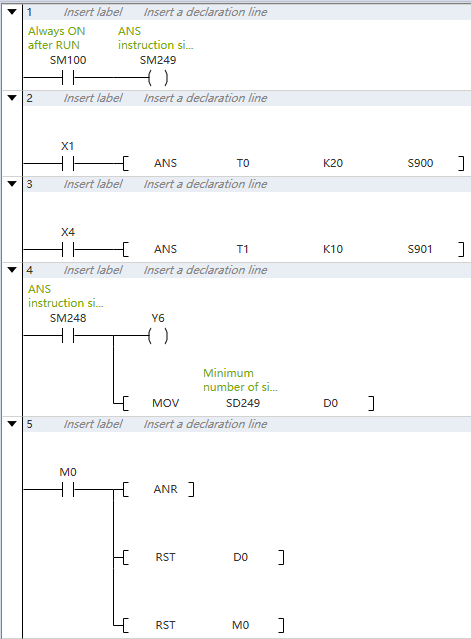
- Monitoring is effective after SM249 is turned ON.
- Detect X1 for 2 seconds, turn ON, set S900.
- X4 is detected for 1 second, turn ON, set S901.
- SM248 will act after any one of S900 to S999 is ON, and the output fault display YY6 will act.
- Display the fault number to the D0 device.
- Through the external fault diagnosis program, use the reset button M0 to turn off the activated state. Each time M0 turns ON, the action status of the new number is set in turn, and the new number that is already ON is reset.
ANR/Alarm Reset
ANR(P)
The instruction to reset the small number that is ON in the alarm.
-[ANR]
Content, range and data type
| Parameter | Content | Range | Data type | Data type (label) |
|---|---|---|---|---|
| No | No parameter setting | - | - | - |
Device used
| instruction | Parameter | Devices | Index modification | Pulse extension | |||||||||||||||||||||||
|---|---|---|---|---|---|---|---|---|---|---|---|---|---|---|---|---|---|---|---|---|---|---|---|---|---|---|---|
| X | Y | M | S | SM | T(bit) | C(bit) | LC(bit) | HSC(bit) | D.b | KnX | KnY | KnM | KnS | T | C | D | R | SD | LC | HSC | K | H | E | [D] | XXP | ||
| ANR | No | No object device | |||||||||||||||||||||||||
Features
If the instruction input is ON, reset the active alarm in the alarm.
If multiple alarms are operating, reset the smaller number. If the input instruction is turned ON again, the next small number in the alarm that is operating will be reset.
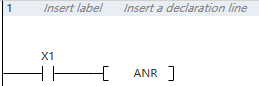
Related device
| Devices | Name | Content |
|---|---|---|
| SM249 | Signal alarm is valid | After SM249 is ON, the following SM248 and SD249 act. |
| SM248 | Signal alarm action | SM249 is ON, when any one of the states S900 to S999 is active, SM248 is ON. |
| SD249 | Signal alarm ON state minimum number | Save the smallest number of actions in S900 to S999. |
Error code
No operation error.
Example
The fault number is displayed by the signal alarm.
As shown below, when you write a program for diagnosing external faults, such as monitoring the content of SM249 (the smallest number in the ON state), the smallest number in the ON state among S900 to S999 will be displayed. When multiple faults occur at the same time, the next fault number can be obtained after eliminating the fault with the smallest number.
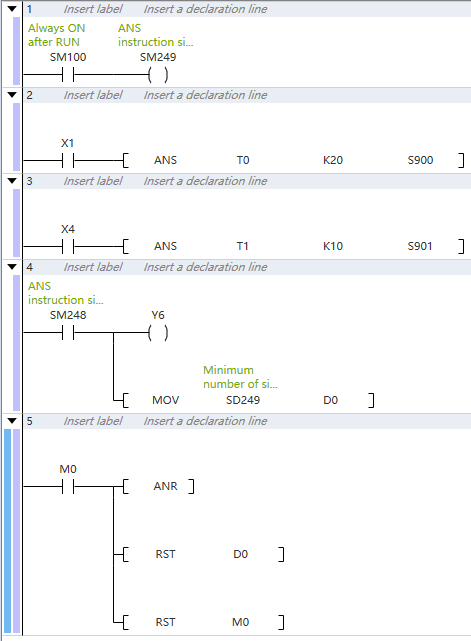
- Monitoring is effective after SM249 is turned ON.
- Detect X1 for 2 seconds, turn ON, set S900.
- X4 is detected for 1 second, turn ON, set S901.
- SM248 will act after any one of S900 to S999 is ON, and the output fault display YY6 will act.
- Display the fault number to the D0 device.
- Through the external fault diagnosis program, use the reset button M0 to turn off the activated state. Each time M0 turns ON, the action status of the new number is set in turn, and the new number that is already ON is reset.
BON/16-bit Data Bit Judgment
BON(P)
Check whether the state of the BIN 16-bit data (n) bit of the device specified in (s) is ON or OFF, and output the result to the device specified in (d).
-[BON (s) (n) (d)]
Content, range and data type
| Parameter | Content | Range | Data type | Data type (label) |
|---|---|---|---|---|
| (s) | Data storage destination word device number | - | Signed BIN 16 bit | ANY16 |
| (d) | Bit device number of drive | - | Bit | ANY16_BOOL |
| (n) | The position of the bit to be judged | 0 to 15 | Signed BIN 16 bit | ANY16 |
Device used
| instruction | Parameter | Devices | Index modification | Pulse extension | |||||||||||||||||||||||
|---|---|---|---|---|---|---|---|---|---|---|---|---|---|---|---|---|---|---|---|---|---|---|---|---|---|---|---|
| X | Y | M | S | SM | T(bit) | C(bit) | LC(bit) | HSC(bit) | D.b | KnX | KnY | KnM | KnS | T | C | D | R | SD | LC | HSC | K | H | E | [D] | XXP | ||
| BON | Parameter 1 | ● | ● | ● | ● | ● | ● | ● | ● | ● | ● | ● | ● | ● | |||||||||||||
| Parameter 2 | ● | ● | ● | ● | ● | ● | ● | ● | ● | ● | |||||||||||||||||
| Parameter 3 | ● | ● | ● | ● | ● | ● | ● | ● | ● | ● | ● | ● | ● | ||||||||||||||
Features
Check whether the state of the BIN 16-bit data (n) bit of the device specified in (s) is ON or OFF, and output the result to the device specified in (d).
If the above result is ON, then (d)=ON, if it is OFF, then (d)=OFF.
If a constant (K) is specified in the device specified in (s), it will be automatically converted to BIN.
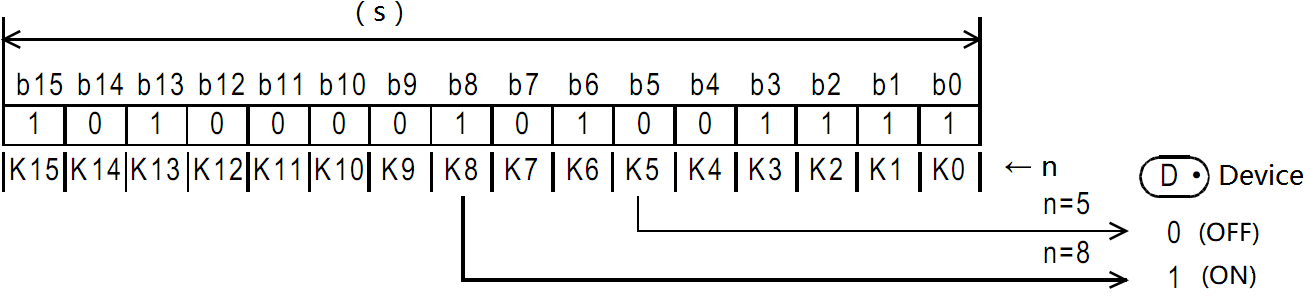
Error code
| Error code | Content |
|---|---|
| 4084H | The data input in (n) exceeds the specified range of 0 to 15. |
| 4085H | When the device specified in the read application instructions (s) and (n) exceeds the corresponding device range |
| 4086H | When the device specified in the write application instruction (d) exceeds the corresponding device range |
Example
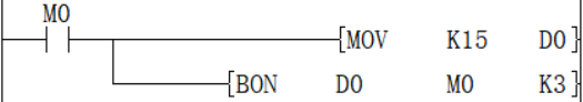
When n in D0 = the third bit is 1 (ON), M0 is set to 1 (ON).
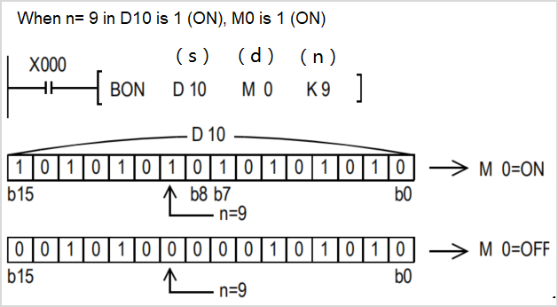
DBON/32-bit Data Bit Judgment
DBON(P)
Check whether the state of the BIN 32-bit data (n) bit of the device specified in (s) is ON or OFF, and output the result to the device specified in (d).
-[DBON (s) (n) (d)]
Content, range and data type
| Parameter | Content | Range | Data type | Data type (label) |
|---|---|---|---|---|
| (s) | Data storage destination word device number | - | Signed BIN 32 bit | ANY32 |
| (d) | Bit device number of drive | - | Bit | ANY32_BOOL |
| (n) | The position of the bit to be judged | 0 to 31 | Signed BIN 32 bit | ANY32 |
Device used
| instruction | Parameter | Devices | Index modification | Pulse extension | |||||||||||||||||||||||
|---|---|---|---|---|---|---|---|---|---|---|---|---|---|---|---|---|---|---|---|---|---|---|---|---|---|---|---|
| X | Y | M | S | SM | T(bit) | C(bit) | LC(bit) | HSC(bit) | D.b | KnX | KnY | KnM | KnS | T | C | D | R | SD | LC | HSC | K | H | E | [D] | XXP | ||
| DBON | Parameter 1 | ● | ● | ● | ● | ● | ● | ● | ● | ● | ● | ● | ● | ● | ● | ● | |||||||||||
| Parameter 2 | ● | ● | ● | ● | ● | ● | ● | ● | ● | ● | |||||||||||||||||
| Parameter 3 | ● | ● | ● | ● | ● | ● | ● | ● | ● | ● | ● | ● | ● | ● | ● | ||||||||||||
Features
Check whether the BIN 32-bit data (n) bit status of the device specified in (s) is ON or OFF, and output the result to the device specified in (d).
If the above result is ON, then (d)=ON, if it is OFF, then (d)=OFF.
If a constant (K) is specified in the device specified in (s), it will be automatically converted to BIN.

Error code
| Error code | Content |
|---|---|
| 4084H | The data input in (n) exceeds the specified range of 0 to 31. |
| 4085H | When the device specified in the read application instructions (s) and (n) exceeds the corresponding device range |
| 4086H | When the device specified in the write application instruction (d) exceeds the corresponding device range |
Example
When n in D0 = the third bit is 1 (ON), M0 is set to 1 (ON).
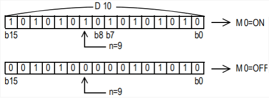
ENCO/Encode
ENCO(P)
Encode the data of the 2th (n)th power from (s) and store it in (d).
-[ENCO (s) (n) (d)]
Content, range and data type
| Parameter | Content | Range | Data type | Data type (label) |
|---|---|---|---|---|
| (s) | Start device for storing coded data | - | Bit/Signed BIN 16 bit | ANY_ELEMENTARY |
| (d) | Device number storing the encoding result | - | Signed BIN 16 bit | ANY_ELEMENTARY |
| (n) | Effective bit length | 0 to 8 | Signed BIN 16 bit | ANY16 |
Device used
| instruction | Parameter | Devices | Index modification | Pulse extension | |||||||||||||||||||||||
|---|---|---|---|---|---|---|---|---|---|---|---|---|---|---|---|---|---|---|---|---|---|---|---|---|---|---|---|
| X | Y | M | S | SM | T(bit) | C(bit) | LC(bit) | HSC(bit) | D.b | KnX | KnY | KnM | KnS | T | C | D | R | SD | LC | HSC | K | H | E | [D] | XXP | ||
| ENCO | Parameter 1 | ● | ● | ● | ● | ● | ● | ● | ● | ● | ● | ● | ● | ||||||||||||||
| Parameter 2 | ● | ● | ● | ● | ● | ● | ● | ● | ● | ● | |||||||||||||||||
| Parameter 3 | ● | ● | ● | ● | ● | ● | ● | ● | ● | ● | ● | ● | ● | ||||||||||||||
Features
The BIN value corresponding to the bit from 2 (n) bits of (s) to 1 is stored in (d).
When (n)=0, it w

ill be no processing, and the content of the device specified in (d) will not change.
Bit devices are treated as 1 bit, and word devices are treated as 16 bits.
When multiple digits are 1, it will be processed at the upper position.
Error code
| Error code | Content |
|---|---|
| 4084H | In the bit device specification of (s), when (n) is other than 0 to 8. |
| In the word device specification of (s), when (n) is other than 0 to 4. | |
| When the data of 2(n) bits starting from (s) are all 0. | |
| 4085H | When the device specified in the read application instructions (s) and (n) exceeds the corresponding device range |
| 4086H | When the device specified in the write application instruction (d) exceeds the corresponding device range |
Example

When M20 is turned ON, the D0 device is 16 after encoding.
DECO/Decode
DECO(P)
Decode the lower (n) bits of the device specified in (s), and store the result in the 2 (n)th power of the device specified in (d).
-[DECO (s) (n) (d)]
Content, range and data type
| Parameter | Content | Range | Data type | Data type (label) |
|---|---|---|---|---|
| (s) | Decoded data or the device number storing the decoded data | - | Bit/Signed BIN 16 bit | ANY_ELEMENTARY |
| (d) | The start device storing the decoding result | - | Signed BIN 16 bit | ANY_ELEMENTARY |
| (n) | Effective bit length | 0 to 8 | Signed BIN 16 bit | ANY16 |
Device used
| instruction | Parameter | Devices | Index modification | Pulse extension | |||||||||||||||||||||||
|---|---|---|---|---|---|---|---|---|---|---|---|---|---|---|---|---|---|---|---|---|---|---|---|---|---|---|---|
| X | Y | M | S | SM | T(bit) | C(bit) | LC(bit) | HSC(bit) | D.b | KnX | KnY | KnM | KnS | T | C | D | R | SD | LC | HSC | K | H | E | [D] | XXP | ||
| DECO | Parameter 1 | ● | ● | ● | ● | ● | ● | ● | ● | ● | ● | ● | ● | ● | ● | ● | ● | ● | |||||||||
| Parameter 2 | ● | ● | ● | ● | ● | ● | ● | ● | ● | ● | ● | ||||||||||||||||
| Parameter 3 | ● | ● | ● | ● | ● | ● | ● | ● | ● | ● | ● | ● | ● | ||||||||||||||
Features
Turn ON the position of (d) corresponding to the BIN value specified in the lower (n) bit of (s).
When (n)=0, it will be no processing, and the content of the device specified in (d) will not change.
Bit devices are treated as 1 bit, and word devices are treated as 16 bits.

Error code
| Error code | Content |
|---|---|
| 4084H | In the bit device specification of (d), when (n) is other than 0 to 8. |
| In the word device specification of (d), when (n) is other than 0 to 4. | |
| 4085H | When the device specified in the read application instructions (s) and (n) exceeds the corresponding device range |
| 4086H | When the device specified in the write application instruction (d) exceeds the corresponding device range |
Example

When M20 is ON, M3 will be turned ON.
SUM/The ON Bits of 16-bit Data
SUM(P)
Store the total number of bits at 1 in the BIN 16-bit data of the device specified in (s) to the device specified in (d).
-[SUM (s) (d)]
Content, range and data type
| Parameter | Content | Range | Data type | Data type (label) |
|---|---|---|---|---|
| (s) | The device start number that counts the total number of bits at 1 | - | Signed BIN 16 bit | ANY16 |
| (d) | The device start number of the total number of storage bits | - | Signed BIN 16 bit | ANY16 |
Device used
| instruction | Parameter | Devices | Index modification | Pulse extension | |||||||||||||||||||||||
|---|---|---|---|---|---|---|---|---|---|---|---|---|---|---|---|---|---|---|---|---|---|---|---|---|---|---|---|
| X | Y | M | S | SM | T(bit) | C(bit) | LC(bit) | HSC(bit) | D.b | KnX | KnY | KnM | KnS | T | C | D | R | SD | LC | HSC | K | H | E | [D] | XXP | ||
| SUM | Parameter 1 | ● | ● | ● | ● | ● | ● | ● | ● | ● | ● | ● | ● | ● | |||||||||||||
| Parameter 2 | ● | ● | ● | ● | ● | ● | ● | ● | ● | ● | |||||||||||||||||
Features
Store the total number of bits at 1 in the BIN 16-bit data of the device specified in (s) to the device specified in (d).
When the BIN 16-bit data of the device specified in (s) is all 0, the zero flag (SM153) turns on.

- The total number of 1 (ON) is stored in BIN.
- There are 8 in the example on the left.
Error code
| Error code | Content |
|---|---|
| 4085H | When the device specified in the read application instructions (s) exceeds the corresponding device range |
| 4086H | When the device specified in the write application instruction (d) exceeds the corresponding device range |
Example
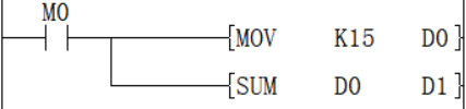
When M0 is ON, the number of ON bits in D0 is counted and stored in D1. The value after D1 is executed is 4.
DSUM/The ON Bits of 32-bit Data
DSUM(P)
Store the total number of bits at 1 in the BIN 32-bit data of the device specified in (s) to the device specified in (d).
-[SUM (s) (d)]
Content, range and data type
| Parameter | Content | Range | Data type | Data type (label) |
|---|---|---|---|---|
| (s) | The device start number that counts the total number of bits at 1 | - | Signed BIN 32 bit | ANY32 |
| (d) | The device start number of the total number of storage bits | - | Signed BIN 32 bit | ANY32 |
Device used
| instruction | Parameter | Devices | Index modification | Pulse extension | |||||||||||||||||||||||
|---|---|---|---|---|---|---|---|---|---|---|---|---|---|---|---|---|---|---|---|---|---|---|---|---|---|---|---|
| X | Y | M | S | SM | T(bit) | C(bit) | LC(bit) | HSC(bit) | D.b | KnX | KnY | KnM | KnS | T | C | D | R | SD | LC | HSC | K | H | E | [D] | XXP | ||
| DSUM | Parameter 1 | ● | ● | ● | ● | ● | ● | ● | ● | ● | ● | ● | ● | ● | ● | ● | |||||||||||
| Parameter 2 | ● | ● | ● | ● | ● | ● | ● | ● | ● | ● | ● | ● | |||||||||||||||
Features
Store the total number of bits at 1 in the BIN 32-bit data of the device specified in (s) to the device specified in (d).
When the BIN 32-bit data of the device specified in (s) is all 0 (OFF), the zero flag (SM153) turns on.
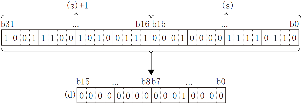
The total number of 1 (ON) is stored in BIN.
There are 16 in the example on the left.
Error code
| Error code | Content |
|---|---|
| 4085H | When the device specified in the read application instructions (s) exceeds the corresponding device range |
| 4086H | When the device specified in the write application instruction (d) exceeds the corresponding device range |
Example
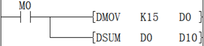
When M0 is ON, the number of ON bits in D0 is counted and stored in D10, and the value after D10 is executed is 4.
MEAN/Average Value of 16-bit Data
MEAN(P)
Store the total number of bits at 1 in the BIN 16-bit data of the device specified in (s) to the device specified in (d).
-[MEAN (s) (d) (n)]
Content, range and data type
| Parameter | Content | Range | Data type | Data type (label) |
|---|---|---|---|---|
| (s) | The device start number storing the data for average calculation | - | Signed BIN 16 bit | ANY16 |
| (d) | The device start number storing the average value | - | Signed BIN 16 bit | ANY16 |
| (n) | Number of data or the device number storing the number of data | 1 to 32767 | Signed BIN 16 bit | ANY16 |
Device used
| instruction | Parameter | Devices | Index modification | Pulse extension | |||||||||||||||||||||||
|---|---|---|---|---|---|---|---|---|---|---|---|---|---|---|---|---|---|---|---|---|---|---|---|---|---|---|---|
| X | Y | M | S | SM | T(bit) | C(bit) | LC(bit) | HSC(bit) | D.b | KnX | KnY | KnM | KnS | T | C | D | R | SD | LC | HSC | K | H | E | [D] | XXP | ||
| MEAN | Parameter 1 | ● | ● | ● | ● | ● | ● | ● | ● | ● | ● | ● | |||||||||||||||
| Parameter 2 | ● | ● | ● | ● | ● | ● | ● | ● | ● | ● | |||||||||||||||||
| Parameter 3 | ● | ● | ● | ● | ● | ● | ● | ● | ● | ● | ● | ● | ● | ||||||||||||||
Features
Calculate the average value of the 16-bit data at (n) points starting from the device specified in (s) and store it in the device specified in (d).
The total is calculated from the algebraic sum and divided by (n).
The remainder is rounded off.
Error code
| Error code | Content |
| 4084H | The data input by (n) in the application instruction exceeds the specifiable range. N≤0 |
| 4085H | When the device specified in the read application instructions (s) and (n) exceeds the corresponding device range |
| 4086H | When the device specified in the write application instruction (d) exceeds the corresponding device range |
Example
Add the data of D0, D1, and D2 and save the value obtained after dividing by 3 in D10. The calculated average value is 6.
DMEAN/Average Value of 16-bit Data
DMEAN(P)
Store the total number of bits at 1 in the BIN 32-bit data of the device specified in (s) to the device specified in (d).
-[DMEAN (s) (d) (n)]
Content, range and data type
| Parameter | Content | Range | Data type | Data type (label) |
|---|---|---|---|---|
| (s) | The device start number storing the data for average calculation | - | Signed BIN 32 bit | ANY32 |
| (d) | The device start number storing the average value | - | Signed BIN 32 bit | ANY32 |
| (n) | Number of data or the device number storing the number of data | 1 to 2147483647 | Signed BIN 32 bit | ANY32 |
Device used
| instruction | Parameter | Devices | Index modification | Pulse extension | |||||||||||||||||||||||
|---|---|---|---|---|---|---|---|---|---|---|---|---|---|---|---|---|---|---|---|---|---|---|---|---|---|---|---|
| X | Y | M | S | SM | T(bit) | C(bit) | LC(bit) | HSC(bit) | D.b | KnX | KnY | KnM | KnS | T | C | D | R | SD | LC | HSC | K | H | E | [D] | XXP | ||
| DMEAN | Parameter 1 | ● | ● | ● | ● | ● | ● | ● | ● | ● | ● | ● | ● | ● | |||||||||||||
| Parameter 2 | ● | ● | ● | ● | ● | ● | ● | ● | ● | ● | ● | ● | |||||||||||||||
| Parameter 3 | ● | ● | ● | ● | ● | ● | ● | ● | ● | ● | ● | ● | ● | ● | ● | ||||||||||||
Features
Calculate the mean value of BIN 32-bit data at (n) points starting from the device specified in (s) and store it in the device specified in (d).
The total is calculated from the algebraic sum and divided by (n).
The remainder is rounded off.
Error code
| Error code | Content |
|---|---|
| 4084H | The data input in (n) exceeds the specifiable range. N≤0 |
| 4085H | When the device specified in the read application instructions (s) and (n) exceeds the corresponding device range |
| 4086H | When the device specified in the write application instruction (d) exceeds the corresponding device range |
Example
Add the data of D0, D2, and D4, and save the value obtained after dividing by 3 in D10 and D11, and the calculated average value is 6.
SQR/16-bit Square Root
SQR(P)
Calculate the square root of the BIN 16-bit data specified in (s), and store the calculation result in (d).
-[SQR (s) (d)]
Content, range and data type
| Parameter | Content | Range | Data type | Data type (label) |
|---|---|---|---|---|
| (s) | The data device storing for square root calculation | 0 to +32767 | Signed BIN 16 bit | ANY16 |
| (d) | The device storing the calculated square root | - | Signed BIN 16 bit | ANY16 |
Device used
| instruction | Parameter | Devices | Index modification | Pulse extension | |||||||||||||||||||||||
|---|---|---|---|---|---|---|---|---|---|---|---|---|---|---|---|---|---|---|---|---|---|---|---|---|---|---|---|
| X | Y | M | S | SM | T(bit) | C(bit) | LC(bit) | HSC(bit) | D.b | KnX | KnY | KnM | KnS | T | C | D | R | SD | LC | HSC | K | H | E | [D] | XXP | ||
| SQR | Parameter 1 | ● | ● | ● | ● | ● | ● | ● | |||||||||||||||||||
| Parameter 2 | ● | ● | ● | ● | ● | ||||||||||||||||||||||
Features
Calculate the square root of the BIN 16-bit data specified in (s), and store the calculation result in (d).
Error code
| Error code | Content |
| 4084H | When a negative value is specified in (s). |
| 4085H | When the device specified in the read application instructions (s) exceeds the corresponding device range |
| 4086H | When the device specified in the write application instruction (d) exceeds the corresponding device range |
Example
The square root of D0 is stored in D2, and the value of D0 is 100, so the value of D2 is 10.
DSQR/32-bit Square Root
DSQR(P)
Calculate the square root of the BIN 32-bit data specified in (s), and store the calculation result in (d).
-[DSQR (s) (d)]
Content, range and data type
| Parameter | Content | Range | Data type | Data type (label) |
|---|---|---|---|---|
| (s) | The data device storing for square root calculation | 0 to 2147483647 | Signed BIN 32 bit | ANY32 |
| (d) | The device storing the calculated square root | - | Signed BIN 32 bit | ANY32 |
Device used
| instruction | Parameter | Devices | Index modification | Pulse extension | |||||||||||||||||||||||
|---|---|---|---|---|---|---|---|---|---|---|---|---|---|---|---|---|---|---|---|---|---|---|---|---|---|---|---|
| X | Y | M | S | SM | T(bit) | C(bit) | LC(bit) | HSC(bit) | D.b | KnX | KnY | KnM | KnS | T | C | D | R | SD | LC | HSC | K | H | E | [D] | XXP | ||
| DSQR | Parameter 1 | ● | ● | ● | ● | ● | ● | ● | ● | ● | |||||||||||||||||
| Parameter 2 | ● | ● | ● | ● | ● | ● | ● | ||||||||||||||||||||
Features
Calculate the square root of the BIN 32-bit data specified in (s) and store the calculation result in (d).
Error code
| Error code | Content |
|---|---|
| 4084H | When a negative value is specified in (s). |
| 4085H | When the device specified in the read application instructions (s) exceeds the corresponding device range |
| 4086H | When the device specified in the write application instruction (d) exceeds the corresponding device range |
Example
The square root of D0 is stored in D2, and the value of D0 is 110, so the value in the D2 device is 10 (the fractional part is discarded), and the borrow flag SM152 is turned ON.
WSUM/The Sum Value of 16-bit Data
WSUM(P)
After adding all the BIN 16-bit data of point (n) starting from the device specified in (s), it is stored in the device specified in (d).
-[WSUM (s) (d) (n)]
Content, range and data type
| Parameter | Content | Range | Data type | Data type (label) |
|---|---|---|---|---|
| (s) | The device start number storing the data for sum value calculation | - | Signed BIN 16 bit | ANY16 |
| (d) | The device start number storing the sum value | - | Signed BIN 32 bit | ANY32 |
| (n) | Number of data | - | Signed BIN 16 bit | ANY16 |
Device used
| instruction | Parameter | Devices | Index modification | Pulse extension | |||||||||||||||||||||||
|---|---|---|---|---|---|---|---|---|---|---|---|---|---|---|---|---|---|---|---|---|---|---|---|---|---|---|---|
| X | Y | M | S | SM | T(bit) | C(bit) | LC(bit) | HSC(bit) | D.b | KnX | KnY | KnM | KnS | T | C | D | R | SD | LC | HSC | K | H | E | [D] | XXP | ||
| WSUM | Parameter 1 | ● | ● | ● | ● | ● | ● | ● | |||||||||||||||||||
| Parameter 2 | ● | ● | ● | ● | ● | ● | ● | ● | ● | ● | |||||||||||||||||
| Parameter 3 | ● | ● | ● | ● | ● | ● | ● | ● | ● | ● | ● | ● | ● | ||||||||||||||
Features
After adding all the BIN 16-bit data of point (n) starting from the device specified in (s), it is stored in the device specified in (d).
Error code
| Error code | Content |
|---|---|
| 4084H | When a negative value is specified in (n). |
| 4085H | When the device specified in the read application instructions (s) and (n) exceeds the corresponding device range |
| 4086H | When the device specified in the write application instruction (d) exceeds the corresponding device range |
Example
When M0=ON, the total of 16-bit data of D0 to D2 is saved in [D100, D101], and the accounting result is 18.
DWSUM/The Sum Value of 32-bit Data
 DWSUM(P)
Add all the 32-bit BIN data of point (n) starting from the device specified in (s) and store it in the device specified in (d).
-[DWSUM (s) (d) (n)]
Content, range and data type
| Parameter | Content | Range | Data type | Data type (label) |
|---|---|---|---|---|
| (s) | The device start number storing the data for total value calculation | - | Signed BIN 32 bit | ANY32 |
| (d) | The device start number storing the total value | - | Signed BIN64 bit | ANY64 |
| (n) | Number of data | - | Signed BIN 32 bit | ANY32 |
Device used
| instruction | Parameter | Devices | Index modification | Pulse extension | |||||||||||||||||||||||
|---|---|---|---|---|---|---|---|---|---|---|---|---|---|---|---|---|---|---|---|---|---|---|---|---|---|---|---|
| X | Y | M | S | SM | T(bit) | C(bit) | LC(bit) | HSC(bit) | D.b | KnX | KnY | KnM | KnS | T | C | D | R | SD | LC | HSC | K | H | E | [D] | XXP | ||
| DWSUM | Parameter 1 | ● | ● | ● | ● | ● | ● | ● | ● | ● | |||||||||||||||||
| Parameter 2 | ● | ● | ● | ● | ● | ● | ● | ● | ● | ● | ● | ● | |||||||||||||||
| Parameter 3 | ● | ● | ● | ● | ● | ● | ● | ● | ● | ● | ● | ● | ● | ● | ● | ||||||||||||
Features
Add all the 32-bit BIN data of point (n) starting from the device specified in (s) and store it in the device specified in (d).
Error code
| Error code | Content |
|---|---|
| 4084H | When a negative value is specified in (n). |
| 4085H | When the device specified in the read application instructions (s) and (n) exceeds the corresponding device range |
| 4086H | When the device specified in the write application instruction (d) exceeds the corresponding device range |
Example
When M0=ON, the total of 16-bit data of D0 to D2 is saved in [D100, D101], and the accounting result is 18.
SORT/16-bit Data Sorting
SORT
Sort the data rows in ascending order based on the group data of column (n3) in the BIN 16-bit data table (sorting source) of (n1×n2) points specified in (s) and store them in the specified in (d) (N1×n2) points in the BIN 16-bit data table (after sorting).
-[SORT (s) (n1) (n2) (d) (n3)]
Content, range and data type
| Parameter | Content | Range | Data type | Data type (label) |
|---|---|---|---|---|
| (s) | The start device number storing the data table | - | Signed BIN 16 bit | ANY16 |
| (n1) | Number of data (rows) | 1 to 32 | Signed BIN 16 bit | ANY16 |
| (n2) | Number of group data (columns) | 1 to 6 | Signed BIN 16 bit | ANY16 |
| (d) | The start device number storing the operation result | - | Signed BIN 16 bit | ANY16 |
| (n3) | The column number of the group data (column) as the sorting basis | - | Signed BIN 16 bit | ANY16 |
Device used
| instruction | Parameter | Devices | Index modification | Pulse extension | |||||||||||||||||||||||
|---|---|---|---|---|---|---|---|---|---|---|---|---|---|---|---|---|---|---|---|---|---|---|---|---|---|---|---|
| X | Y | M | S | SM | T(bit) | C(bit) | LC(bit) | HSC(bit) | D.b | KnX | KnY | KnM | KnS | T | C | D | R | SD | LC | HSC | K | H | E | [D] | XXP | ||
| SORT | Parameter 1 | ● | ● | ● | ● | ● | ● | ||||||||||||||||||||
| Parameter 2 | ● | ● | ● | ● | ● | ● | ● | ● | ● | ● | ● | ● | |||||||||||||||
| Parameter 3 | ● | ● | ● | ● | ● | ● | ● | ● | ● | ● | ● | ● | |||||||||||||||
| Parameter 4 | ● | ● | ● | ● | ● | ● | |||||||||||||||||||||
| Parameter 5 | ● | ● | ● | ● | ● | ● | ● | ● | ● | ● | ● | ● | |||||||||||||||
Features
The BIN 16-bit data table (sorting source) of (n1×n2) points specified in (s), based on the group data of column (n3), sort the data rows in ascending order, and store them in (d). The (n1×n2) point of the BIN 16-bit data table (after sorting).
Take (n1)=K3, (n2)=K4 in the sort source as an example, the data table structure is as follows. In the case of a sorted data table, (s) should be replaced with (d).
| Number of groups (n2) ((n2)=K4) | |||||
|---|---|---|---|---|---|
| Column NO. 1 | Column NO. 2 | Column NO. 3 | Column NO. 4 | ||
| Management number | Height | Weight | Age | ||
| When the number of data (n1)=3 | Line NO.1 | (s) | (s) +3 | (s) +6 | (s) +9 |
| Line NO.2 | (s)+1 | (s) +4 | (s) +7 | (s) +10 | |
| Line NO.3 | (s)+2 | (s) +5 | (s) +8 | (s) +11 | |
Data alignment starts when instruction input is ON, data alignment ends after (n1) scan, instruction execution end flag SM229 is set to ON. According to the source data sorted as follows, an example of the operation is shown below. In addition, by putting serial numbers such as management numbers in the first column in advance, the original row number can be judged based on the content, which is very convenient.
| Number of groups (n2) ((n2)=K4) | |||||
|---|---|---|---|---|---|
| Column NO. 1 | Column NO. 2 | Column NO. 3 | Column NO. 4 | ||
| Management number | Height | Weight | Age | ||
| When the number of data (n1) = 5 | Line NO.1 | (s) | (s) +5 | (s) +10 | (s) +15 |
| 1 | 150 | 45 | 20 | ||
| Line NO.2 | (s)+1 | (s) +6 | (s) +11 | (s) +16 | |
| 2 | 180 | 50 | 40 | ||
| Line NO.3 | (s)+2 | (s) +7 | (s) +12 | (s) +17 | |
| 3 | 160 | 70 | 30 | ||
| Line NO.4 | (s) +3 | (s) +8 | (s) +13 | (s) +18 | |
| 4 | 100 | 20 | 8 | ||
| Line NO.5 | (s) +4 | (s) +9 | (s) +14 | (s) +19 | |
| 5 | 150 | 50 | 45 | ||
Press (n3)=K2 (column number 2) to execute the sorting result.
| Number of groups (n2) ((n2)=K4) | |||||
|---|---|---|---|---|---|
| Column NO.1 | Column NO.2 | Column NO.3 | Column NO.4 | ||
| Management number | Height | Weight | Age | ||
| When the number of data (n1) = 5 | Line NO.1 | (d) | (d) +5 | (d) +10 | (d) +15 |
| 4 | 100 | 20 | 8 | ||
| Line NO.2 | (d) +1 | (d) +6 | (d) +11 | (d) +16 | |
| 1 | 150 | 45 | 20 | ||
| Line NO.3 | (d) +2 | (d) +7 | (d) +12 | (d) +17 | |
| 5 | 150 | 50 | 45 | ||
| Line NO.4 | (d) +3 | (d) +8 | (d) +13 | (d) +18 | |
| 3 | 160 | 70 | 30 | ||
| Line NO.5 | (d) +4 | (d) +9 | (d) +14 | (d) +19 | |
| 2 | 180 | 50 | 40 | ||
Press (n3)=K3 (column number 3) to execute the sorting result.
| Number of groups (n2) ((n2)=K4) | |||||
|---|---|---|---|---|---|
| Column NO.1 | Column NO.2 | Column NO.3 | Column NO.4 | ||
| Management number | Height | Weight | Age | ||
| When the number of data (n1) = 5 | Line NO.1 | (d) | (d) +5 | (d) +10 | (d) +15 |
| 4 | 100 | 20 | 8 | ||
| Line NO.2 | (d) +1 | (d) +6 | (d) +11 | (d) +16 | |
| 1 | 150 | 45 | 20 | ||
| Line NO.3 | (d) +2 | (d) +7 | (d) +12 | (d) +17 | |
| 2 | 180 | 50 | 40 | ||
| Line NO.4 | (d) +3 | (d) +8 | (d) +13 | (d) +18 | |
| 5 | 150 | 50 | 45 | ||
| Line NO.5 | (d) +4 | (d) +9 | (d) +14 | (d) +19 | |
| 3 | 160 | 70 | 30 | ||
Error code
| Error code | Content |
|---|---|
| 4084H | When the value specified in (n1) exceeds the range of 1 to 32 |
| When the value specified in (n2) exceeds the range of 1 to 6 | |
| When the value specified in (n3) exceeds the range of 1 to n2 | |
| 4085H | When the device specified in read application instruction (s), (n1), (n2 )and (n3) exceeds the corresponding device range |
| 4086H | When the device specified in the write application instruction (d) exceeds the corresponding device range |
| 4087H | When the (d) parameter in the application instruction uses an unsupported device |
| 4089H | The number of application instructions exceeds the limit. |
Example
Refer to the function description example.
SORT2/16-bit Data Sorting
SORT2(P)
Sort the data rows in ascending or descending order based on the group data in column (n3), and store them in (d), based on the BIN 16-bit data table (sorting source) of (n1×n2) points specified in (s) In the BIN 16-bit data table (after sorting) of the specified (n1×n2) points.
-[SORT2 (s) (n1) (n2) (d) (n3)]
Content, range and data type
| Parameter | Content | Range | Data type | Data type (label) |
|---|---|---|---|---|
| (s) | The start device number storing the data table | - | Signed BIN 16 bit | ANY16 |
| (n1) | Number of data (rows) | 1 to 32 | Signed BIN 16 bit | ANY16 |
| (n2) | Number of group data (columns) | 1 to 6 | Signed BIN 16 bit | ANY16 |
| (d) | The start device number storing the operation result | - | Signed BIN 16 bit | ANY16 |
| (n3) | The column number of the group data (column) as the sorting basis | - | Signed BIN 16 bit | ANY16 |
Device used
| instruction | Parameter | Devices | Index modification | Pulse extension | |||||||||||||||||||||||
|---|---|---|---|---|---|---|---|---|---|---|---|---|---|---|---|---|---|---|---|---|---|---|---|---|---|---|---|
| X | Y | M | S | SM | T(bit) | C(bit) | LC(bit) | HSC(bit) | D.b | KnX | KnY | KnM | KnS | T | C | D | R | SD | LC | HSC | K | H | E | [D] | XXP | ||
| SORT2 | Parameter 1 | ● | ● | ● | ● | ● | ● | ||||||||||||||||||||
| Parameter 2 | ● | ● | ● | ● | ● | ● | ● | ● | ● | ● | ● | ● | |||||||||||||||
| Parameter 3 | ● | ● | ● | ● | ● | ● | ● | ● | ● | ● | ● | ● | |||||||||||||||
| Parameter 4 | ● | ● | ● | ● | ● | ● | |||||||||||||||||||||
| Parameter 5 | ● | ● | ● | ● | ● | ● | ● | ● | ● | ● | ● | ● | |||||||||||||||
Features
Sort the data rows in ascending or descending order based on the group data in column (n3) and store them in (d) (N1×n2) point specified in the BIN 16-bit data table (after sorting).
Take (n1)=K3, (n2)=K4 in the sort source as an example, the data table structure is as follows. In the case of a sorted data table, (s) should be replaced with (d).
| When the number of groups (n2) (n2) = K4 | |||||
|---|---|---|---|---|---|
| Column NO.1 | Column NO.2 | Column NO.3 | Column NO.4 | ||
| Management number | Height | Weight | Age | ||
| When the number of data (n1)=3 | Line NO.1 | (s) | (s)+1 | (s) +2 | (s) +3 |
| Line NO.2 | (s) +4 | (s) +5 | (s) +6 | (s) +7 | |
| Line NO.3 | (s) +8 | (s) +9 | (s) +10 | (s) +100 | |
Sequence is set by the ON/OFF status of SM165
| Sort order setting instruction | |
|---|---|
| SM165=ON | Descending |
| SM165=OFF | Ascending |
Data alignment starts when instruction input is ON, data alignment ends after (n1) scan, instruction execution end flag SM229 is set to ON.
According to the source data sorted as follows, an example of the operation is shown below. In addition, by putting serial numbers such as management numbers in the first column in advance, the original row number can be judged based on the content, which is very convenient.
| When the number of groups (n2) (n2) = K4 | |||||
|---|---|---|---|---|---|
| Column NO.1 | Column NO.2 | Column NO.3 | Column NO.4 | ||
| Management number | Height | Weight | Age | ||
| When the number of data (n1) = 5 | Line NO.1 | (s) | (s)+1 | (s) +2 | (s) +3 |
| 1 | 150 | 45 | 20 | ||
| Line NO.2 | (s) +4 | (s) +5 | (s) +6 | (s) +7 | |
| 2 | 180 | 50 | 40 | ||
| Line NO.3 | (s) +8 | (s) +9 | (s) +10 | (s) +100 | |
| 3 | 160 | 70 | 30 | ||
| Line NO.4 | (s) +12 | (s) +13 | (s) +14 | (s) +15 | |
| 4 | 100 | 20 | 8 | ||
| Line NO.5 | (s) +16 | (s) +17 | (s) +18 | (s) +19 | |
| 5 | 150 | 50 | 45 | ||
Press (n3)=K2 (column number 2) to execute the sorting result (SM165=OFF in the case of ascending order)
| When the number of groups (n2) (n2) = K4 | |||||
|---|---|---|---|---|---|
| Column NO.1 | Column NO.2 | Column NO.3 | Column NO.4 | ||
| Management number | Height | Weight | Age | ||
| When the number of data (n1) = 5 | Line NO.1 | (d) | (d) +1 | (d) +2 | (d) +3 |
| 4 | 100 | 20 | 8 | ||
| Line NO.2 | (d) +4 | (d) +5 | (d) +6 | (d) +7 | |
| 1 | 150 | 45 | 20 | ||
| Line NO.3 | (d) +8 | (d) +9 | (d) +10 | (d) +100 | |
| 5 | 150 | 50 | 45 | ||
| Line NO.4 | (d) +12 | (d) +13 | (d) +14 | (d) +15 | |
| 3 | 160 | 70 | 30 | ||
| Line NO.5 | (d) +16 | (d) +17 | (d) +18 | (d) +19 | |
| 2 | 180 | 50 | 40 | ||
Press (n3)=K3 (column number 3) to execute the sorting result (SM165=ON in the case of ascending order)
| When the number of groups (n2) (n2) = K4 | |||||
|---|---|---|---|---|---|
| Column NO.1 | Column NO.2 | Column NO.3 | Column NO.4 | ||
| Management number | Height | Weight | Age | ||
| When the number of data (n1) = 5 | Line NO.1 | (d) | (d) +1 | (d) +2 | (d) +3 |
| 3 | 160 | 70 | 30 | ||
| Line NO.2 | (d) +4 | (d) +5 | (d) +6 | (d) +7 | |
| 2 | 180 | 50 | 40 | ||
| Line NO.3 | (d) +8 | (d) +9 | (d) +10 | (d) +100 | |
| 5 | 150 | 50 | 45 | ||
| Line NO.4 | (d) +12 | (d) +13 | (d) +14 | (d) +15 | |
| 1 | 150 | 45 | 20 | ||
| Line NO.5 | (d) +16 | (d) +17 | (d) +18 | (d) +19 | |
| 4 | 100 | 20 | 8 | ||
Error code
| Error code | Content |
|---|---|
| 4084H | When the value specified in (n1) exceeds the range of 1 to 32 |
| When the value specified in (n2) exceeds the range of 1 to 6 | |
| When the value specified in (n3) exceeds the range of 1 to n2 | |
| 4085H | When the device specified in read application instruction (s), (d), (n1), (n2) and (n3) exceeds the corresponding device range |
| 4086H | When the device specified in the write application instruction (d) exceeds the corresponding device range |
| 4089H | The number of application instructions exceeded the limit. |
Example
Refer to the function description example.
DSORT2/32-bit Data Sorting
DSORT2(P)
Sort the data rows in ascending or descending order based on the group data of column (n3) in the BIN 32-bit data table (sorting source) of (n1×n2) points specified in (s) and store them in (d) The specified (n1×n2) point BIN 32-bit data table (after sorting).
-[DSORT2 (s) (n1) (n2) (d) (n3)]
Content, range and data type
| Parameter | Content | Range | Data type | Data type (label) |
|---|---|---|---|---|
| (s) | The start device number storing the data table | - | Signed BIN 32 bit | ANY32 |
| (n1) | Number of data (rows) | 1 to 32 | Signed BIN 32 bit | ANY32 |
| (n2) | Number of group data (columns) | 1 to 6 | Signed BIN 32 bit | ANY32 |
| (d) | The start device number storing the operation result | - | Signed BIN 32 bit | ANY32 |
| (n3) | The column number of the group data (column) as the sorting basis | - | Signed BIN 32 bit | ANY32 |
Device used
| instruction | Parameter | Devices | Index modification | Pulse extension | |||||||||||||||||||||||
|---|---|---|---|---|---|---|---|---|---|---|---|---|---|---|---|---|---|---|---|---|---|---|---|---|---|---|---|
| X | Y | M | S | SM | T(bit) | C(bit) | LC(bit) | HSC(bit) | D.b | KnX | KnY | KnM | KnS | T | C | D | R | SD | LC | HSC | K | H | E | [D] | XXP | ||
| DSORT2 | Parameter 1 | ● | ● | ● | ● | ● | ● | ● | ● | ||||||||||||||||||
| Parameter 2 | ● | ● | ● | ● | ● | ● | ● | ● | ● | ● | ● | ● | ● | ● | |||||||||||||
| Parameter 3 | ● | ● | ● | ● | ● | ● | ● | ● | ● | ● | ● | ● | ● | ● | |||||||||||||
| Parameter 4 | ● | ● | ● | ● | ● | ● | ● | ● | |||||||||||||||||||
| Parameter 5 | ● | ● | ● | ● | ● | ● | ● | ● | ● | ● | ● | ● | ● | ● | |||||||||||||
Features
Sort the data rows in ascending or descending order based on the group data in the (n3) column of the (n1×n2) point BIN 32-bit data table (sorting source) specified in (s), and store to (d) (N1×n2) specified in the BIN 32-bit data table (after sorting).
Take (n1)=K3, (n2)=K4 in the sort source as an example, the data table structure is as follows. In the case of a sorted data table, (s) should be replaced with (d).
| When the number of groups (n2) (n2) = K4 | |||||
|---|---|---|---|---|---|
| Column NO.1 | Column NO.2 | Column NO.3 | Column NO.4 | ||
| Management number | Height | Weight | Age | ||
| When the number of data (n1)=3 | Line NO.1 | (s)+1, (s) | (s)+3, (s)+2 | (s)+5, (s)+4 | (s) +7, (s) +6 |
| Line NO.2 | (s) +9, (s) +8 | (s)+11, (s)+10 | (s) +13, (s) +12 | (s) +15, (s) +14 | |
| Line NO.3 | (s) +17, (s) +16 | (s) +19, (s) +18 | (s) +21, (s) +20 | (s) +23, (s) +22 | |
Sequence is set by the ON/OFF status of SM165
| Sort order setting instructions | |
|---|---|
| SM165=ON | Descending |
| SM165=OFF | Ascending |
Data alignment starts when instruction input is ON, data alignment ends after (n1) scan, instruction execution end flag SM229 is set to ON.
According to the source data sorted as follows, an example of the operation is shown below. In addition, by putting serial numbers such as management numbers in the first column in advance, the original row number can be judged based on the content, which is very convenient.
| When the number of groups (n2) (n2) = K4 | |||||
|---|---|---|---|---|---|
| Column NO.1 | Column NO.2 | Column NO.3 | Column NO.4 | ||
| Management number | height | body weight | age | ||
| When the number of data (n1) = 5 | Line NO.1 | (s)+1, (s) | (s)+3, (s)+2 | (s)+5, (s)+4 | (s) +7, (s) +6 |
| 1 | 150 | 45 | 20 | ||
| Line NO.2 | (s) +9, (s) +8 | (s)+11, (s)+10 | (s) +13, (s) +12 | (s) +15, (s) +14 | |
| 2 | 180 | 50 | 40 | ||
| Line NO.3 | (s) +17, (s) +16 | (s) +19, (s) +18 | (s) +21, (s) +20 | (s) +23, (s) +22 | |
| 3 | 160 | 70 | 30 | ||
| Line NO.4 | (s) +25, (s) +24 | (s) +27, (s) +26 | (s) +29, (s) +28 | (s) +31, (s) +30 | |
| 4 | 100 | 20 | 8 | ||
| Line NO.5 | (s) +33, (s) +32 | (s) +35, (s) +34 | (s) +37, (s) +36 | (s) +39, (s) +38 | |
| 5 | 150 | 50 | 45 | ||
Press (n3)=K2 (column NO.2) to execute the sorting result (SM165=OFF in the case of ascending order)
| When the number of groups (n2) (n2) = K4 | |||||
|---|---|---|---|---|---|
| Column NO.1 | Column NO.2 | Column NO.3 | Column NO.4 | ||
| Management number | height | body weight | age | ||
| When the number of data (n1) = 5 | Line NO.1 | (s)+1, (s) | (s)+3, (s)+2 | (s)+5, (s)+4 | (s) +7, (s) +6 |
| 4 | 100 | 20 | 8 | ||
| Line NO.2 | (s) +9, (s) +8 | (s)+11, (s)+10 | (s) +13, (s) +12 | (s) +15, (s) +14 | |
| 1 | 150 | 45 | 20 | ||
| Line NO.3 | (s) +17, (s) +16 | (s) +19, (s) +18 | (s) +21, (s) +20 | (s) +23, (s) +22 | |
| 5 | 150 | 50 | 45 | ||
| Line NO.4 | (s) +25, (s) +24 | (s) +27, (s) +26 | (s) +29, (s) +28 | (s) +31, (s) +30 | |
| 3 | 160 | 70 | 30 | ||
| Line NO.5 | (s) +33, (s) +32 | (s) +35, (s) +34 | (s) +37, (s) +36 | (s) +39, (s) +38 | |
| 2 | 180 | 50 | 40 | ||
Press (n3)=K3 (column NO.3) to execute the sorting result (SM165=ON in the case of ascending order)
| When the number of groups (n2) (n2) = K4 | |||||
|---|---|---|---|---|---|
| Column NO.1 | Column NO.2 | Column NO.3 | Column NO.4 | ||
| Management number | height | body weight | age | ||
| When the number of data (n1) = 5 | Line NO.1 | (s)+1, (s) | (s)+3, (s)+2 | (s)+5, (s)+4 | (s) +7, (s) +6 |
| 3 | 160 | 70 | 30 | ||
| Line NO.2 | (s) +9, (s) +8 | (s)+11, (s)+10 | (s) +13, (s) +12 | (s) +15, (s) +14 | |
| 2 | 180 | 50 | 40 | ||
| Line NO.3 | (s) +17, (s) +16 | (s) +19, (s) +18 | (s) +21, (s) +20 | (s) +23, (s) +22 | |
| 5 | 150 | 50 | 45 | ||
| Line NO.4 | (s) +25, (s) +24 | (s) +27, (s) +26 | (s) +29, (s) +28 | (s) +31, (s) +30 | |
| 1 | 150 | 45 | 20 | ||
| Line NO.5 | (s) +33, (s) +32 | (s) +35, (s) +34 | (s) +37, (s) +36 | (s) +39, (s) +38 | |
| 4 | 100 | 20 | 8 | ||
✎Note:
Do not change the operand and data content during operation.
When executing again, the instruction input should be turned OFF once.
The SORT2 instruction can only be written twice in the program.
When the same device is specified in (s) and (d), the source data is rewritten to the sorted data order. Please pay special attention not to change the content of (s) before the end of execution.
Do not overlap the source data and the sorted data.
DSORT2(P)
Sort the data rows in ascending or descending order based on the group data of column (n3) in the BIN 32-bit data table (sorting source) of (n1×n2) points specified in (s) and store them in (d) The specified (n1×n2) point BIN 32-bit data table (after sorting).
-[DSORT2 (s) (n1) (n2) (d) (n3)]
Content, range and data type
| Parameter | Content | Range | Data type | Data type (label) |
| (s) | The start device number storing the data table | - | Signed BIN 32 bit | ANY32 |
| (n1) | Number of data (rows) | 1 to 32 | Signed BIN 32 bit | ANY32 |
| (n2) | Number of group data (columns) | 1 to 6 | Signed BIN 32 bit | ANY32 |
| (d) | The start device number storing the operation result | - | Signed BIN 32 bit | ANY32 |
| (n3) | The column number of the group data (column) as the sorting basis | - | Signed BIN 32 bit | ANY32 |
Device used
| instruction | Parameter | Devices | Index modification | Pulse extension | |||||||||||||||||||||||
| X | Y | M | S | SM | T(bit) | C(bit) | LC(bit) | HSC(bit) | D.b | KnX | KnY | KnM | KnS | T | C | D | R | SD | LC | HSC | K | H | E | [D] | XXP | ||
| DSORT2 | Parameter 1 | ● | ● | ● | ● | ● | ● | ● | ● | ||||||||||||||||||
| Parameter 2 | ● | ● | ● | ● | ● | ● | ● | ● | ● | ● | ● | ● | ● | ● | |||||||||||||
| Parameter 3 | ● | ● | ● | ● | ● | ● | ● | ● | ● | ● | ● | ● | ● | ● | |||||||||||||
| Parameter 4 | ● | ● | ● | ● | ● | ● | ● | ● | |||||||||||||||||||
| Parameter 5 | ● | ● | ● | ● | ● | ● | ● | ● | ● | ● | ● | ● | ● | ● | |||||||||||||
Features
Sort the data rows in ascending or descending order based on the group data in the (n3) column of the (n1×n2) point BIN 32-bit data table (sorting source) specified in (s), and store to (d) (N1×n2) specified in the BIN 32-bit data table (after sorting).
Take (n1)=K3, (n2)=K4 in the sort source as an example, the data table structure is as follows. In the case of a sorted data table, (s) should be replaced with (d).
| When the number of groups (n2) (n2) = K4 | |||||
| Column NO.1 | Column NO.2 | Column NO.3 | Column NO.4 | ||
| Management number | Height | Weight | Age | ||
| When the number of data (n1)=3 | Line NO.1 | (s)+1, (s) | (s)+3, (s)+2 | (s)+5, (s)+4 | (s) +7, (s) +6 |
| Line NO.2 | (s) +9, (s) +8 | (s)+11, (s)+10 | (s) +13, (s) +12 | (s) +15, (s) +14 | |
| Line NO.3 | (s) +17, (s) +16 | (s) +19, (s) +18 | (s) +21, (s) +20 | (s) +23, (s) +22 | |
Sequence is set by the ON/OFF status of SM165
| Sort order setting instructions | |
| SM165=ON | Descending |
| SM165=OFF | Ascending |
Data alignment starts when instruction input is ON, data alignment ends after (n1) scan, instruction execution end flag SM229 is set to ON.
According to the source data sorted as follows, an example of the operation is shown below. In addition, by putting serial numbers such as management numbers in the first column in advance, the original row number can be judged based on the content, which is very convenient.
| When the number of groups (n2) (n2) = K4 | |||||
| Column NO.1 | Column NO.2 | Column NO.3 | Column NO.4 | ||
| Management number | height | body weight | age | ||
| When the number of data (n1) = 5 | Line NO.1 | (s)+1, (s) | (s)+3, (s)+2 | (s)+5, (s)+4 | (s) +7, (s) +6 |
| 1 | 150 | 45 | 20 | ||
| Line NO.2 | (s) +9, (s) +8 | (s)+11, (s)+10 | (s) +13, (s) +12 | (s) +15, (s) +14 | |
| 2 | 180 | 50 | 40 | ||
| Line NO.3 | (s) +17, (s) +16 | (s) +19, (s) +18 | (s) +21, (s) +20 | (s) +23, (s) +22 | |
| 3 | 160 | 70 | 30 | ||
| Line NO.4 | (s) +25, (s) +24 | (s) +27, (s) +26 | (s) +29, (s) +28 | (s) +31, (s) +30 | |
| 4 | 100 | 20 | 8 | ||
| Line NO.5 | (s) +33, (s) +32 | (s) +35, (s) +34 | (s) +37, (s) +36 | (s) +39, (s) +38 | |
| 5 | 150 | 50 | 45 | ||
Press (n3)=K2 (column NO.2) to execute the sorting result (SM165=OFF in the case of ascending order)
| When the number of groups (n2) (n2) = K4 | |||||
| Column NO.1 | Column NO.2 | Column NO.3 | Column NO.4 | ||
| Management number | height | body weight | age | ||
| When the number of data (n1) = 5 | Line NO.1 | (s)+1, (s) | (s)+3, (s)+2 | (s)+5, (s)+4 | (s) +7, (s) +6 |
| 4 | 100 | 20 | 8 | ||
| Line NO.2 | (s) +9, (s) +8 | (s)+11, (s)+10 | (s) +13, (s) +12 | (s) +15, (s) +14 | |
| 1 | 150 | 45 | 20 | ||
| Line NO.3 | (s) +17, (s) +16 | (s) +19, (s) +18 | (s) +21, (s) +20 | (s) +23, (s) +22 | |
| 5 | 150 | 50 | 45 | ||
| Line NO.4 | (s) +25, (s) +24 | (s) +27, (s) +26 | (s) +29, (s) +28 | (s) +31, (s) +30 | |
| 3 | 160 | 70 | 30 | ||
| Line NO.5 | (s) +33, (s) +32 | (s) +35, (s) +34 | (s) +37, (s) +36 | (s) +39, (s) +38 | |
| 2 | 180 | 50 | 40 | ||
Press (n3)=K3 (column NO.3) to execute the sorting result (SM165=ON in the case of ascending order)
| When the number of groups (n2) (n2) = K4 | |||||
| Column NO.1 | Column NO.2 | Column NO.3 | Column NO.4 | ||
| Management number | height | body weight | age | ||
| When the number of data (n1) = 5 | Line NO.1 | (s)+1, (s) | (s)+3, (s)+2 | (s)+5, (s)+4 | (s) +7, (s) +6 |
| 3 | 160 | 70 | 30 | ||
| Line NO.2 | (s) +9, (s) +8 | (s)+11, (s)+10 | (s) +13, (s) +12 | (s) +15, (s) +14 | |
| 2 | 180 | 50 | 40 | ||
| Line NO.3 | (s) +17, (s) +16 | (s) +19, (s) +18 | (s) +21, (s) +20 | (s) +23, (s) +22 | |
| 5 | 150 | 50 | 45 | ||
| Line NO.4 | (s) +25, (s) +24 | (s) +27, (s) +26 | (s) +29, (s) +28 | (s) +31, (s) +30 | |
| 1 | 150 | 45 | 20 | ||
| Line NO.5 | (s) +33, (s) +32 | (s) +35, (s) +34 | (s) +37, (s) +36 | (s) +39, (s) +38 | |
| 4 | 100 | 20 | 8 | ||
Error code
| Error code | Content |
|---|---|
| 4084H | When the value specified in (n1) exceeds the range of 1 to 32 |
| When the value specified in (n2) exceeds the range of 1 to 6 | |
| When the value specified in (n3) exceeds the range of 1 to n2 | |
| 4085H | When the device specified in read application instruction (s), (d), (n1), (n2 )and (n3) exceeds the corresponding device range |
| 4086H | When the device specified in the write application instruction (d) exceeds the corresponding device range |
| 4089H | The number of application instructions exceeded the limit. |
Example
Refer to the function description example.
SWAP/16-bit Data High and Low Byte Swap
SWAP(P)
Swap the high and low 8-bit value of the device specified in (d).
-[SWAP (d)]
Content, range and data type
| Parameter | Content | Range | Data type | Data type (label) |
|---|---|---|---|---|
| (d) | Word device with high and low byte swap | - | Signed BIN 16 bit | ANY16 |
Device used
| instruction | Parameter | Devices | Index modification | Pulse extension | |||||||||||||||||||||||
|---|---|---|---|---|---|---|---|---|---|---|---|---|---|---|---|---|---|---|---|---|---|---|---|---|---|---|---|
| X | Y | M | S | SM | T(bit) | C(bit) | LC(bit) | HSC(bit) | D.b | KnX | KnY | KnM | KnS | T | C | D | R | SD | LC | HSC | K | H | E | [D] | XXP | ||
| SWAP | Parameter 1 | ● | ● | ● | ● | ● | ● | ● | ● | ● | ● | ||||||||||||||||
Features
Convert the high and low 8-bit value of the device specified in (d).
Error code
| Error code | Content |
|---|---|
| 4085H | When the device specified in the read application instruction (d) exceeds the corresponding device range |
| 4086H | When the device specified in the write application instruction (d) exceeds the corresponding device range |
Example
When the rising edge of M0 is triggered, swap the low 8 bits and high 8 bits of D0 to get H8F2A.
DSWAP/32-bit Data High and Low Byte Swap
DSWAP(P)
The devices specified in (d) and (d)+1 will be converted to the high and low 8-bit values respectively.
-[DSWAP (d)]
Content, range and data type
| Parameter | Content | Range | Data type | Data type (label) |
|---|---|---|---|---|
| (d) | Word device with high and low byte swap | - | Signed BIN 32 bit | ANY32 |
Device used
| instruction | Parameter | Devices | Index modification | Pulse extension | |||||||||||||||||||||||
|---|---|---|---|---|---|---|---|---|---|---|---|---|---|---|---|---|---|---|---|---|---|---|---|---|---|---|---|
| X | Y | M | S | SM | T(bit) | C(bit) | LC(bit) | HSC(bit) | D.b | KnX | KnY | KnM | KnS | T | C | D | R | SD | LC | HSC | K | H | E | [D] | XXP | ||
| DSWAP | Parameter 1 | ● | ● | ● | ● | ● | ● | ● | ● | ● | ● | ● | ● | ||||||||||||||
Features
The devices specified in (d) and (d)+1 will be converted to the upper and lower 8-bit values respectively.
Error code
| Error code | Content |
|---|---|
| 4085H | When the device specified in the read application instruction (d) exceeds the corresponding device range |
| 4086H | When the device specified in the write application instruction (d) exceeds the corresponding device range |
Example
When the rising edge of M0 is triggered, the low 8 bits and the high 8 bits of D0 and D1 are swapped, and D0=H8F2A, D1=H3412 are obtained.
BTOW/Byte Unit Data Merge
BTOW(P)
Combine the low 8 bits of (n) bytes of BIN 16-bit data stored after the device number specified in (s) into word units and store it after the device number specified in (d).
-[BTOW (s) (d) (n)]
Content, range and data type
| Parameter | Content | Range | Data type | Data type (label) |
|---|---|---|---|---|
| (s) | The start device that stores the data merging in byte units | - | Signed BIN 16 bit | ANY16 |
| (d) | The start device that stores the result of merging in byte units | - | Signed BIN 16 bit | ANY16 |
| (n) | Number of byte data merged | 0-32767 | Signed BIN 16 bit | ANY16 |
Device used
| instruction | Parameter | Devices | Index modification | Pulse extension | |||||||||||||||||||||||
|---|---|---|---|---|---|---|---|---|---|---|---|---|---|---|---|---|---|---|---|---|---|---|---|---|---|---|---|
| X | Y | M | S | SM | T(bit) | C(bit) | LC(bit) | HSC(bit) | D.b | KnX | KnY | KnM | KnS | T | C | D | R | SD | LC | HSC | K | H | E | [D] | XXP | ||
| BTOW | Parameter 1 | ● | ● | ● | ● | ● | ● | ● | |||||||||||||||||||
| Parameter 2 | ● | ● | ● | ● | ● | ● | ● | ||||||||||||||||||||
| Parameter 3 | ● | ● | ● | ● | ● | ● | ● | ● | ● | ● | ● | ● | ● | ||||||||||||||
Features
After the device number specified in (s), the lower 8 bits of the 16-bit BIN data stored in (n) bytes are combined into word units and stored in the device number specified in (d) or later.
The upper 8 bits of (n) word data stored after the device number specified in (s) will be ignored. In addition, when (n) is an odd number, 0 is stored in the upper 8 bits of the device storing the (n)th byte of data.
£: the £th byte data;
(1): Ignore the high byte
*1: Carry below the decimal point.
Example
When (n)=5, the data up to the lower 8 bits of (s)+(s)+4 is stored in (d)+(d)+2.
(1): When (n)=5
(2): Change to 00H
By setting the number of bytes in (n), the range of byte data specified in (s) and the range of the device storing the combined data specified in (d) will be automatically determined.
When the number of bytes specified in (n) is 0, no processing is performed.
The upper 8 bits of the byte data storage device specified in (s) will be ignored, and the lower 8 bits will be the target.
Example
When the low 8 bits of D11 to D16 is stored in D12 to D14.
Even if the device range storing the data before merging overlaps the device rangestoring merged data, it will be handled as normal.
| Device range storing the data before merging | Device range for storing merged data |
| (S)+0 to (s)+(n)-1 | (D) to (d) + (n/2-1) |
Error code
| Error code | Content |
|---|---|
| 4084H | The value specified in (n) exceed range of 0 to 32767 |
| 4085H | When the device specified in the write application instruction (s),(d) and (n) exceeds the corresponding device range |
Example
When M0 is ON, the data of D20 to D25 is separated according to byte units, and then stored in D10 to D12.
WTOB/Byte Unit Data Separation
WTOB(P)
After separating the BIN 16-bit data stored after the device number specified in (s) into (n) bytes, store it after the device number specified in (d).
-[WTOB (s) (d) (n)]
Content, range and data type
| Parameter | Content | Range | Data type | Data type (label) |
|---|---|---|---|---|
| (s) | The start device that stores the data separation in byte unit | - | Signed BIN 16 bit | ANY16 |
| (d) | The start device that stores the result of separation in byte unit | - | Signed BIN 16 bit | ANY16 |
| (n) | Number of byte data separated | 0-32767 | Signed BIN 16 bit | ANY16 |
Device used
| instruction | Parameter | Devices | Index modification | Pulse extension | |||||||||||||||||||||||
|---|---|---|---|---|---|---|---|---|---|---|---|---|---|---|---|---|---|---|---|---|---|---|---|---|---|---|---|
| X | Y | M | S | SM | T(bit) | C(bit) | LC(bit) | HSC(bit) | D.b | KnX | KnY | KnM | KnS | T | C | D | R | SD | LC | HSC | K | H | E | [D] | XXP | ||
| WTOB | Parameter 1 | ● | ● | ● | ● | ● | ● | ● | |||||||||||||||||||
| Parameter 2 | ● | ● | ● | ● | ● | ● | ● | ||||||||||||||||||||
| Parameter 3 | ● | ● | ● | ● | ● | ● | ● | ||||||||||||||||||||
Features
After separating the BIN 16-bit data stored after the device number specified in (s) into (n) bytes, store it after the device number specified in (d).
- High byte;
- Low byte;
- High byte data;
- Low byte data;
- *1: Carry below the decimal point.
Example
In the case of (n)=5, store the data up to the lower 8 bits of (s) to (s)+2 in (d) to (d)+4:
- (N)=5 is ignored.
- (N)=5.
By setting the number of bytes in (n), the range of BIN 16-bit data specified in (s) and the range of the device storing the byte data specified in (d) will be automatically determined.
When the number of bytes specified in (n) is 0, no processing is performed.
00H is automatically stored in the upper 8 bits of the byte data storage device specified in (d).
Example
When D12 to D14 is stored in the low 8 bits of D11 to D16
Even if the device range storing the data before merging overlaps the device rangestoring merged data, it will be handled as normal.
| Device range storing the data before merging | Device range storing separated data |
|---|---|
| (s) to (s) + (n/2-1) | (d)+0 to (d)+(n)-1 |
Error code
| Error code | Content |
|---|---|
| 4084H | The value specified by (n) exceed the range of 0 to 32767 |
| 4085H | When the device specified in read application instruction (s) and (n) exceeds the corresponding device range |
| 4086H | When the device specified in the write application instruction (d) exceeds the corresponding device range |
Example
When M0 is ON, the data of D10 to D12 are separated according to byte units, and then stored in D20 to D25.
DIS/4-bit Separation of 16-bit Data
DIS(P)
Store the data of the low (n) bits (1 bit of 4 bits) of the BIN 16-bit data specified in (s) into the low 4-bit of the (n) point starting from the device specified in (d).
-[DIS (s) (d) (n)]
Content, range and data type
| Parameter | Content | Range | Data type | Data type (label) |
|---|---|---|---|---|
| (s) | The start device storing the data before separation | - | Signed BIN 16 bit | ANY16 |
| (d) | The start device storing separated data | - | Signed BIN 16 bit | ANY16 |
| (n) | Separation number (0 means no processing) | 0-4 | Signed BIN 16 bit | ANY16 |
Device used
| instruction | Parameter | Devices | Index modification | Pulse extension | |||||||||||||||||||||||
|---|---|---|---|---|---|---|---|---|---|---|---|---|---|---|---|---|---|---|---|---|---|---|---|---|---|---|---|
| X | Y | M | S | SM | T(bit) | C(bit) | LC(bit) | HSC(bit) | D.b | KnX | KnY | KnM | KnS | T | C | D | R | SD | LC | HSC | K | H | E | [D] | XXP | ||
| DIS | Parameter 1 | ● | ● | ● | ● | ● | ● | ● | ● | ● | ● | ● | ● | ● | |||||||||||||
| Parameter 2 | ● | ● | ● | ● | ● | ● | ● | ||||||||||||||||||||
| Parameter 3 | ● | ● | ● | ● | ● | ● | ● | ● | ● | ● | ● | ● | ● | ||||||||||||||
Features
Store the low-(n) bit (1 bits of 4 bits) of the BIN 16-bit data specified in (s) in the low 4-bit of the (n) point starting from the device specified in (d).
The hig-12 bit of the point (n) starting from the device specified in (s) will become 0.
When (n)=0, it will become no processing, and the content of point (n) starting from the device of (d) will not change.
Error code
| Error code | Content |
|---|---|
| 4084H | The data in (n) exceed the range of 0 to 4 |
| 4085H | When the device specified in read application instruction (s) and (n) exceeds the corresponding device range |
| 4086H | When the device specified in the write application instruction (d) exceeds the corresponding device range |
Example
When M0 is ON, D0 is separated every 4 bits and stored in D10 to D12. The result is D10 = HF, D11 = H8, D12 = HA.
UNI/4-bit Combination of 16-bit Data
UNI(P)
Combine the low 4 bits of the BIN 16-bit data of point (n) starting from the device specified in (s) into the BIN 16-bit device specified in (d).
-[UNI (s) (d) (n)]
Content, range and data type
| Parameter | Content | Range | Data type | Data type (label) |
|---|---|---|---|---|
| (s) | The start device storing the data before merging | - | Signed BIN 16 bit | ANY16 |
| (d) | The start device storing the merged data | - | Signed BIN 16 bit | ANY16 |
| (n) | Number of merger | 0-4 | Signed BIN 16 bit | ANY16 |
Device used
| instruction | Parameter | Devices | Index modification | Pulse extension | |||||||||||||||||||||||
|---|---|---|---|---|---|---|---|---|---|---|---|---|---|---|---|---|---|---|---|---|---|---|---|---|---|---|---|
| X | Y | M | S | SM | T(bit) | C(bit) | LC(bit) | HSC(bit) | D.b | KnX | KnY | KnM | KnS | T | C | D | R | SD | LC | HSC | K | H | E | [D] | XXP | ||
| UNI | Parameter 1 | ● | ● | ● | ● | ● | ● | ● | |||||||||||||||||||
| Parameter 2 | ● | ● | ● | ● | ● | ● | ● | ● | ● | ● | |||||||||||||||||
| Parameter 3 | ● | ● | ● | ● | ● | ● | ● | ● | ● | ● | ● | ● | ● | ||||||||||||||
Features
Combine the low 4 bits of the BIN 16-bit data at point (n) starting from the device specified in (s) into the BIN 16-bit device specified in (d).
The high (4-n) bits of the device specified in (d) will become 0.
When (n)=0, it will become no processing, and the content of the device in (d) will not change.
Error code
| Code | Content |
|---|---|
| 4084H | The data in (n) exceed the range of 0 to 4 |
| 4085H | When the device specified in read application instruction (s) and (n) exceeds the corresponding device range |
| 4086H | When the device specified in the write application instruction (d) exceeds the corresponding device range |
Example
When M0 is ON, the low 4 bits of D0 to D3 are combined and stored in D10, the value is H236F.
ZRST/Data Batch Reset
 ZRST(P)
Perform a batch reset between the devices specified in (d1) and (d2) of the same type. It is used when interrupting operation, performing initial operation, or resetting control data.
-[ZRST ( d1) (d2)]
Content, range and data type
| Parameter | Content | Range | Data type | Data type (label) |
|---|---|---|---|---|
| (d1) | The start bit or word device number of batch reset | - | Bit/Signed BIN 16 bit | ANY_ELEMENTARY |
| (d2) | The final bit or word device number of batch reset | - | Bit/Signed BIN 16 bit | ANY_ELEMENTARY |
Device used
| instruction | Parameter | Devices | Index modification | Pulse extension | |||||||||||||||||||||||
|---|---|---|---|---|---|---|---|---|---|---|---|---|---|---|---|---|---|---|---|---|---|---|---|---|---|---|---|
| X | Y | M | S | SM | T(bit) | C(bit) | LC(bit) | HSC(bit) | D.b | KnX | KnY | KnM | KnS | T | C | D | R | SD | LC | HSC | K | H | E | [D] | XXP | ||
| ZRST | Parameter 1 | ● | ● | ● | ● | ● | ● | ● | ● | ● | ● | ● | ● | ● | ● | ● | ● | ● | |||||||||
| Parameter 2 | ● | ● | ● | ● | ● | ● | ● | ● | ● | ● | ● | ● | ● | ● | ● | ● | ● | ||||||||||
Features
Perform batch reset between the devices specified in (d1) and (d2) of the same type.
When (d1) and (d2) are bit devices, write OFF (reset) in the entire device range of (d1) to (d2).
When (d1) and (d2) are word devices, write K0 in the entire device range of (d1) to (d2).
As a separate reset instruction for the device, the RST instruction can be used for bit devices or word devices.
Reset M0
Reset the current value of T0
Reset D0
The batch write instruction of constant (for example: K0) has FMOV (P) instruction, which can write 0 to word devices (including bit device specification).
Write K0 in D0 to D99.
Error code
| Error code | Content |
|---|---|
| 4084H | When the device type specified in (d1) is different from the device type specified in (d2). |
| 4085H | When the device specified in the read application instruction (d1) and (d2) exceeds the corresponding device range |
| 4086H | When the device specified in the write application instruction (d1) exceeds the corresponding device range |
Example
The function of this ladder diagram instruction is to set the value of the D0 to D100 device to 0.
ZSET/Data Batch Set
ZSET(P)
Perform a batch set between the devices specified in (d1) and (d2) of the same type.
Content, range and data type
| Parameter | Content | Range | Data type | Data type(label) |
|---|---|---|---|---|
| (d1) | The start bit device number of batch set | - | Bit | ANY_BOOL |
| (d2) | The final bit device number of batch set | - | Bit | ANY_BOOL |
Device used
| instruction | Parameter | Devices | Index modification | |||||||||||||||||||||||
|---|---|---|---|---|---|---|---|---|---|---|---|---|---|---|---|---|---|---|---|---|---|---|---|---|---|---|
| X | Y | M | S | SM | T(bit) | C(bit) | LC(bit) | HSC(bit) | D.b | KnX | KnY | KnM | KnS | T | C | D | R | SD | LC | HSC | K | H | E | [D] | ||
| ZSET | Parameter 1 | ● | ● | ● | ● | ● | ● | |||||||||||||||||||
| Parameter 2 | ● | ● | ● | ● | ● | ● | ||||||||||||||||||||
Features
·Perform a batch set between the devices specified in (d1) and (d2) of the same type.
·Write ON (set) in the entire device range of (d1) to (d2)
·As a separate set instruction for the device, the SET instruction can be used for bit devices.
Error code
| Error code | Content |
|---|---|
| 4084H | When the device type specified in (d1) is different from the device type specified in (d2). |
| 4085H | When the device specified in the read application instruction (d1) and (d2) exceeds the corresponding device range |
| 4086H | When the device specified in the write application instruction (d1) exceeds the corresponding device range |
| 4087H | When the device type specified in (d1) and (d2) are not bit device. |
Example
The function of this LAD instruction is to set the value of the M1 to M4 device to ON.
CRC/Cyclic Redundancy Check instruction
CRC(P)
Calculate the CRC (Cyclic Redundancy Check) value, which is one of the error checking methods used in communications. In addition to CRC, error checking methods include parity and
Sum check (checksum), calculate horizontal parity check value and sum check value can use CCD(P) instruction . And this instruction is used in the generator polynomial that generates the CRC value (CRC-16)
"X 16 +X 15 +X 2 +1".
-[CRC(P) (s) (d) (n)]
Content, range and data type
| Parameter | Content | Range | Data type | Data type (label) |
|---|---|---|---|---|
| (s) | The device start number storing the data of CRC value generated objects | - | Signed BIN16 | ANY16 |
| (d) | The destination device number of the generated CRC value | - | Signed BIN16 | ANY16 |
| (n) | The number of 8-bit data (bytes) for calculating the CRC value or the number of the device storing the number of data | 1 to 256 | Unsigned BIN16 | ANY16_U |
Device used
| instruction | Parameter | Devices | Index modification | Pulse extension | |||||||||||||||||||||||
|---|---|---|---|---|---|---|---|---|---|---|---|---|---|---|---|---|---|---|---|---|---|---|---|---|---|---|---|
| X | Y | M | S | SM | T(bit) | C(bit) | LC(bit) | HSC(bit) | D.b | KnX | KnY | KnM | KnS | T | C | D | R | SD | LC | HSC | K | H | E | [D] | XXP | ||
| CRC | Parameter 1 | ● | ● | ● | ● | ● | ● | ● | ● | ● | ● | ● | |||||||||||||||
| Parameter 2 | ● | ● | ● | ● | ● | ● | ● | ● | ● | ● | |||||||||||||||||
| Parameter 3 | ● | ● | ● | ● | ● | ● | ● | ● | ● | ● | ● | ● | |||||||||||||||
Features
Start with the device specified in (s), generate the CRC value of 8-bit data (byte unit) at (n) point, and store it in (d).
The mode used by this instruction in calculation includes 16-bit conversion mode and 8-bit conversion mode. For the operation of each mode, please refer to the following content.
- 16-bit conversion mode (when SM161=OFF)
Calculate the upper 8 bits (byte) and lower 8 bits (byte) of the (s) device. The result is stored in 16 bits of 1 point of the device specified in (d). In the case of the following program, perform the conversion as shown below.
| Example (s)=D100, (d)=D0, (n)=6 | |||||
| Devices | Content of object data | ||||
| 8-bit | 16-bit | ||||
| CRC value generation target data storage destination | (s) | Low byte | D100 low | 01H | 0301H |
| High byte | D100 high | 03H | |||
| (s)+1 | Low byte | D101 low | 03H | 0203H | |
| High byte | D101 high | 02H | |||
| (s)+2 | Low byte | D102 low | 00H | 1400H | |
| High byte | D102 high | 14H | |||
| ... | |||||
| (s)+(n)/2-1 | Low byte | ||||
| High byte | |||||
| CRC value storage target | (d) | Low byte | D0 low | E4H | 41E4H |
| High byte | D0 high | 41H | |||
2. 8-bit conversion mode (when SM8161=ON)
In 8-bit conversion mode, only the lower 8 bits (lower byte) of the (s) device are operated on. As a result, 2 points are used starting from the device specified in (d), the lower 8 bits (bytes) are stored in (d), and the upper 8 bits (bytes) are stored in (d)+1.
In the case of the following program, perform the conversion as shown below.
| Example) (s)=D100, (d)=D0, (n)=6 | ||||
| Devices | Content of object data | |||
| CRC value generation target data storage destination | (s) | Low byte | D100 low | 01H |
| (s)+1 | Low byte | D101 low | 03H | |
| (s)+2 | Low byte | D102 low | 03H | |
| (s)+3 | Low byte | D103 low | 02H | |
| (s)+4 | Low byte | D104 low | 00H | |
| (s)+5 | Low byte | D105 low | 14H | |
| ... | ||||
| (s)+(n)-1 | Low byte | |||
| CRC value storage target | (d) | Low byte | D0 | E4H |
| (d)+1 | Low byte | D1 | 41H | |
In the CRC(P) instruction, the generator polynomial of the CRC value (CRC-16) uses "X16+X15+X2+1", but there are also many standardized generator polynomials for the CRC value. If the generator polynomial is different, it will become a completely different CRC value, which should be noted. The main CRC value generator polynomials are shown below.
| Name | Generator polynomial |
|---|---|
| CRC-12 | X12+X11+X3+X2+X+1 |
| CRC-16 | X16+X15+X2+1 |
| CRC-32 | X32+X26+X23+X22+X16+X12+X11+X10+X8+X7+X5+X4+X2+X+1 |
| CRC-CCITT | X16+X12+X5+1 |
Error code
| Error code | Content |
|---|---|
| 4084H | The range of (n) exceeds 1 to 256 |
| 4085H | The data address of (s) to be converted exceeds the device range |
| 4086H | The (d) write address exceeds the device range |
| 4087H | Unsupported device type is used by (s) and (d) |
Example
- 16-bit conversion mode
- 8-bit conversion mode
Matrix Input instructions
MTR/Matrix Input
 MTR
MTR
The instruction to read the input signal (switch) of 8 points multiply by n columns in the time division method of 8 input and (n) output (transistor).
-[MTR (s) (d1) (d2) (n)]
Content, range and data type
| Parameter | Content | Range | Data type | Data type (label) |
|---|---|---|---|---|
| (s) | The start device (X) number X000, X010, X020 of the row signal input of the matrix is up to the final input X number. 8 consecutively occupied. | The lowest bit number of X can only be 0 | Bit
| ANY_BOOL |
| (d1) | The starting device (Y) number of the column signal output of the matrix is Y000, Y010, Y020... to the final output Y number. 8 consecutively occupied. | The lowest bit number of Y can only be 0 | Bit | ANY_BOOL |
| (d2) | The start device (Y, M, S) number of the ON output destination address is Y000, Y010, Y020..., M000, M010, M020..., S000, S010, S020... until the final Y, M, S number. Y occupies 8*(n) continuously, and the others occupy 10*(n) continuously. | - | Bit | ANY_BOOL |
| (n) | Set the number of columns in the matrix input. | 2 to 8 | Unsigned BIN 16 bit | ANY16_U |
Device used
| instruction | Parameter | Devices | Index modification | Pulse extension | |||||||||||||||||||||||
|---|---|---|---|---|---|---|---|---|---|---|---|---|---|---|---|---|---|---|---|---|---|---|---|---|---|---|---|
| X | Y | M | S | SM | T(bit) | C(bit) | LC(bit) | HSC(bit) | D.b | KnX | KnY | KnM | KnS | T | C | D | R | SD | LC | HSC | K | H | E | [D] | XXP | ||
| MTR | Parameter 1 | ● | |||||||||||||||||||||||||
| Parameter 2 | ● | ||||||||||||||||||||||||||
| Parameter 3 | ● | ● | ● | ● | |||||||||||||||||||||||
| Parameter 4 | ● | ● | |||||||||||||||||||||||||
Features
This instruction generally uses the normally ON contact SM100.
According to the example in the figure:
M10 will turn ON when Y30 and X30 are connected, M14 will be ON when Y30 and X34 are connected, M26 will be ON when Y31 and X36 are connected
(D2) is recommended to use a minimum of 0, mainly when using an address such as M4, the first start is M4, and then it will continue to occupy M11, which is inconvenient to calculate and view, so it is recommended to use a software with a minimum of 0 element.
Special device used
| Devices | Content |
| SM229 | SM229 will turn ON after one cycle of execution is completed |
Error code
| Error code | Content |
|---|---|
| 4085H | The read address of (s) and (n) exceeds the device range |
| (s) use the numbered device whose low bit is not 0 | |
| 4086HA | The write address of (d1) and (d2) exceeds the device range |
| (d2) use the numbered device whose low bit is not 0 | |
| 4084H | (n) is not in the range of 2 to 8 |
| 4089H | Multiple MTR instructions are executed at the same time |
Convenient instructions
ABSD/BIN 16-bit Data Absolute Method
 ABSD
ABSD
Create multiple output modes corresponding to the current counter (BIN 16-bit value).
-[ABSD (s1) (s2) (d) (n)]
Content, range and data type
| Parameter | Content | Range | Data type | Data type (label) |
|---|---|---|---|---|
| (s1) | The start device number storing the data table (rising edge point and falling edge point) | - | Signed BIN 16 bit | ANY16 |
| (s2) | The counter number used for monitoring of the current value compared to the data table | - | Signed BIN 16 bit | ANY16 |
| (d) | The number of points of the output start device | - | Bit | ANY16_BOOL |
| (n) | Number of table rows and output bit device points | 1 to 64 | Signed BIN 16 bit | ANY16 |
Device used
| instruction | Parameter | Devices | Index modification | Pulse extension | |||||||||||||||||||||||
|---|---|---|---|---|---|---|---|---|---|---|---|---|---|---|---|---|---|---|---|---|---|---|---|---|---|---|---|
| X | Y | M | S | SM | T(bit) | C(bit) | LC(bit) | HSC(bit) | D.b | KnX | KnY | KnM | KnS | T | C | D | R | SD | LC | HSC | K | H | E | [D] | XXP | ||
| ABSD | Parameter 1 | ● | ● | ● | ● | ● | ● | ● | ● | ● | ● | ||||||||||||||||
| Parameter 2 | ● | ● | |||||||||||||||||||||||||
| Parameter 3 | ● | ● | ● | ● | ● | ● | |||||||||||||||||||||
| Parameter 4 | ● | ● | ● | ● | ● | ● | ● | ● | ● | ● | ● | ● | |||||||||||||||
Features
Take the turntable to rotate 1 revolution (0 to 360 degrees) to control the output ON/OFF as an example. (1 degree, 1 pulse angle signal)
Compare the data table of row (n) starting from (s1) (row (n) multiply by 2 points) with the current value of the counter (s2), from (d) to continuous (n) in the course of one revolution The output is ON/OFF control up to the point.
Use the transfer instruction to write the following data into (s1) to (s1)+2(n)-1 in advance. For example, the rising edge point data stores 16-bit data to even-numbered devices in advance, and the falling edge point data stores 16-bit data to odd-numbered devices in advance.
| Rising edge point | Falling edge point | Object output | ||
|---|---|---|---|---|
| - | Data value (example) | - | Data value (example) | |
| (S1) | 40 | (S1)+1 | 140 | (D) |
| (S1)+2 | 100 | (S1) +3 | 200 | (D) +1 |
| (S1) +4 | 160 | (S1) +5 | 60 | (D) +2 |
| (S1) +6 | 240 | (S1) +7 | 280 | (D) +3 |
| ... | - | ... | - | ... |
| (S1)+2(n)-2 | (S1)+2(n)-1 | (D) +n-1 | ||
If the instruction input is set to ON, (d) is the start, (n) point is the output mode as shown below. Each rising edge point and falling edge point can be individually changed by rewriting the data from (s1) to (s1)+2(n)-1.
Error code
| Error code | Content |
|---|---|
| 4084H | When the value specified in (n) exceeds the range of 1 to 64 |
| 4085H | When the device specified in the read application instruction (s1), (s2 )and (n) exceeds the corresponding device range |
| 4086H | When the device specified in the write application instruction (d) exceeds the corresponding device range |
Example
Refer to the example in the function description.
DABSD/BIN 32-bit Data Absolute Method
DABSD
Create multiple output modes corresponding to the current counter (BIN 32-bit value).
-[DABSD (s1) (s2) (d) (n)]
Content, range and data type
| Parameter | Content | Range | Data type | Data type (label) |
|---|---|---|---|---|
| (s1) | The start device number storing the data table (rising edge point and falling edge point) | - | Signed BIN 32 bit | ANY32 |
| (s2) | The counter number used for monitoring of the current value compared to the data table | - | Signed BIN 32 bit | ANY32 |
| (d) | The number of points of the output start device | - | Bit | ANY16_BOOL |
| (n) | Number of table rows and output bit device points | 1 to 64 | Signed BIN 32 bit | ANY32 |
Device used
| instruction | Parameter | Devices | Index modification | Pulse extension | |||||||||||||||||||||||
|---|---|---|---|---|---|---|---|---|---|---|---|---|---|---|---|---|---|---|---|---|---|---|---|---|---|---|---|
| X | Y | M | S | SM | T(bit) | C(bit) | LC(bit) | HSC(bit) | D.b | KnX | KnY | KnM | KnS | T | C | D | R | SD | LC | HSC | K | H | E | [D] | XXP | ||
| DABSD | Parameter 1 | ● | ● | ● | ● | ● | ● | ● | ● | ● | ● | ● | ● | ||||||||||||||
| Parameter 2 | ● | ● | ● | ● | |||||||||||||||||||||||
| Parameter 3 | ● | ● | ● | ● | ● | ● | |||||||||||||||||||||
| Parameter 4 | ● | ● | ● | ● | ● | ● | ● | ● | ● | ● | ● | ● | ● | ● | |||||||||||||
Features
Take the turntable to rotate 1 revolution (0 to 360 degrees) to control the output ON/OFF as an example. (1 degree, 1 pulse angle signal)
Compare the data table of row (n) starting from (s1) (row (n) × 4 points) with the current value of the counter (s2), from (d) to continuous (n) in the course of one revolution The output is ON/OFF control up to the point.
Use the transfer instruction to write the following data into (s1), (s1)+1 to (s1)+4(n)-2, (s1)+4(n)-1 in advance. For example, the rising edge point data stores 32-bit data to even-numbered devices in advance, and the falling edge point data stores 32-bit data to odd-numbered devices in advance.
| Rising edge point | Falling edge point | Object output | ||
|---|---|---|---|---|
| - | Data value (example) | - | Data value (example) | |
| (S1)+1, (S1) | 40 | (S1)+3, (S1)+2 | 140 | (D) |
| (S1)+5, (S1)+4 | 100 | (S1) +7, (S1) +6 | 200 | (D) +1 |
| (S1) +9, (S1) +8 | 160 | (S1)+11, (S1)+10 | 60 | (D) +2 |
| (S1) +13, (S1) +12 | 240 | (S1) +15, (S1) +14 | 280 | (D) +3 |
| ... | - | ... | - | ... |
(S1)+4(n)-3, (S1)+4(n)-4 | (S1)+4(n)-1, (S1)+4(n)-2 | (D) +n-1 | ||
If the instruction input is set to ON, (d) is the start, (n) point is the output mode as shown below. Each rising edge point and falling edge point can be individually changed by rewriting the data from (s1) to (s1)+2(n)-1.
Error code
| Error code | Content |
|---|---|
| 4084H | When the value specified in (n) exceeds the range of 1 to 64 |
| 4085H | When the device specified in the read application instruction (s1), (s2 )and (n) exceeds the corresponding device range |
| 4086H | When the device specified in the write application instruction (d) exceeds the corresponding device range |
Example
Refer to the example in the function description.
SER/16-bit Data Search
SER(P)
Search the same data and the maximum and minimum values from the data table.
-[SER (s1) (s2) (d) (n)]
Content, range and data type
| Parameter | Content | Range | Data type | Data type (label) |
|---|---|---|---|---|
| (s1) | Search for the start device number of the same data, maximum value, and minimum value | - | Signed BIN 16 bit | ANY16 |
| (s2) | Search for the value of the same data or its storage destination device number | - | Signed BIN 16 bit | ANY16 |
| (d) | Search for the same data, maximum value, minimum value and store the start device number | - | Signed BIN 16 bit | ANY16 |
| (n) | Search the number of same data, maximum and minimum | 1 to 256 | Signed BIN 16 bit | ANY16 |
Device used
| instruction | Parameter | Devices | Index modification | Pulse extension | |||||||||||||||||||||||
|---|---|---|---|---|---|---|---|---|---|---|---|---|---|---|---|---|---|---|---|---|---|---|---|---|---|---|---|
| X | Y | M | S | SM | T(bit) | C(bit) | LC(bit) | HSC(bit) | D.b | KnX | KnY | KnM | KnS | T | C | D | R | SD | LC | HSC | K | H | E | [D] | XXP | ||
| SER | Parameter 1 | ● | ● | ● | ● | ● | ● | ● | ● | ● | ● | ● | |||||||||||||||
| Parameter 2 | ● | ● | ● | ● | ● | ● | ● | ● | ● | ● | ● | ● | ● | ||||||||||||||
| Parameter 3 | ● | ● | ● | ● | ● | ● | ● | ● | ● | ● | |||||||||||||||||
| Parameter 4 | ● | ● | ● | ● | ● | ● | ● | ● | ● | ● | ● | ● | ● | ||||||||||||||
Features
For (s1) as the first (n) data, search for the same data as the BIN 16-bit data of (s2), and store the result in (d) to (d)+4.
In the case of the same data, the number of the same data, the first/final position, and the maximum and minimum positions of the same data are stored in the device with the first 5 points (d).
If there is no identical data, the number of identical data, the first/final position, and the maximum and minimum positions of the same data are stored in the device with the first 5 points (d). However, in (d) is the first 3 points of the device (the number of the same data, the first \\ final position), 0 is stored.
• The structure and data examples of the search result table are as follows. (N=10)
| The searched device (s1) | The value of the searched data (s1) | Comparison data (S2) value | Data location | search results | ||
|---|---|---|---|---|---|---|
| Maximum value (d) +4 | Consistent (d) | Minimum value (d+3) | ||||
| (s1) | K100 | K100 | 0 | ○(First time) | ||
| (s1)+1 | K111 | 1 | ||||
| (s1)+2 | K100 | 2 | ○ | |||
| (s1) +3 | K98 | 3 | ||||
| (s1) +4 | K123 | 4 | ||||
| (s1) +5 | K66 | 5 | ○ | |||
| (s1) +6 | K100 | 6 | ○ (final) | |||
| (s1) +7 | K95 | 7 | ||||
| (s1) +8 | 210 | 8 | ○ | |||
| (s1) +9 | K88 | 9 | ||||
• The search result table based on the above example is shown below.
| Device number | Content | Search result items |
|---|---|---|
| (d) | 3 | Number of identical data |
| (d) +1 | 0 | The position of the same data (first time) |
| (d) +2 | 6 | The position of the same data (last time) |
| (d) +3 | 5 | The final position of the minimum |
| (d) +4 | 8 | The final position of maximum |
Error code
| Error code | Content |
|---|---|
| 4084H | When the value specified in (n) exceeds the range of 0 to 256 |
| 4085H | When the device specified in read application instruction (s1), (s2), (d) and (n) exceeds the corresponding device range |
| 4086H | When the device specified in the write application instruction (d) exceeds the corresponding device range |
Example
Refer to the example in the function description.
DSER/32-bit Data Search
 DSER(P)
Search the same data and the maximum and minimum values from the data table.
-[DSER (s1) (s2) (d) (n)]
Content, range and data type
| Parameter | Content | Range | Data type | Data type (label) |
|---|---|---|---|---|
| (s1) | Search for the start device number of the same data, maximum value, and minimum value | - | Signed BIN 32 bit | ANY32 |
| (s2) | Search for the value of the same data or its storage destination device number | - | Signed BIN 32 bit | ANY32 |
| (d) | Search for the same data, maximum value, minimum value and store the start device number | - | Signed BIN 32 bit | ANY32 |
| (n) | Search the number of same data, maximum and minimum | 1 to 128 | Signed BIN 32 bit | ANY32 |
Device used
| instruction | Parameter | Devices | Index modification | Pulse extension | |||||||||||||||||||||||
|---|---|---|---|---|---|---|---|---|---|---|---|---|---|---|---|---|---|---|---|---|---|---|---|---|---|---|---|
| X | Y | M | S | SM | T(bit) | C(bit) | LC(bit) | HSC(bit) | D.b | KnX | KnY | KnM | KnS | T | C | D | R | SD | LC | HSC | K | H | E | [D] | XXP | ||
| DSER | Parameter 1 | ● | ● | ● | ● | ● | ● | ● | ● | ● | ● | ● | ● | ● | |||||||||||||
| Parameter 2 | ● | ● | ● | ● | ● | ● | ● | ● | ● | ● | ● | ● | ● | ● | ● | ||||||||||||
| Parameter 3 | ● | ● | ● | ● | ● | ● | ● | ● | ● | ● | ● | ● | |||||||||||||||
| Parameter 4 | ● | ● | ● | ● | ● | ● | ● | ● | ● | ● | ● | ● | ● | ● | ● | ||||||||||||
Features
For (s1)+1, (s1) as the initial (n) data, search for the same data as the BIN 32-bit data of (s2)+1, (s2), and store the result in (d)+1, (D) to (d) +9, (d) +8.
In the case of the same data, the number of the same data, the first/final position and the maximum and minimum values are stored in a 5-point BIN 32-bit data device starting with (d)+1 and (d) position.
In the case of no identical data, the number of identical data, the first/final position and the maximum and minimum values are stored in the device with (d)+1 and (d) as the starting BIN 32-bit data with 5 points position. However, 0 is stored in the 32-bit 3-point device (the number of the same data, the first\\last position) with (d)+1 and (d) as the starting BIN.
• The structure and data examples of the search result table are as follows. (N=10)
| The searched device (S1) | The value of the searched data (S1) | Comparison data (S2) value | Data location | search results | ||
|---|---|---|---|---|---|---|
| Maximum value (d) +4 | Consistent (d) | Minimum value (d+3) | ||||
| (S1)+1, (S1) | K100 | K100 | 0 | ○ (First time) | ||
| (S1)+3, (S1)+2 | K111 | 1 | ||||
| (S1)+5, (S1)+4 | K100 | 2 | ○ | |||
| (S1) +7, (S1) +6 | K98 | 3 | ||||
| (S1) +9, (S1) +8 | K123 | 4 | ||||
| (S1)+11, (S1)+10 | K66 | 5 | ○ | |||
| (S1) +13, (S1) +12 | K100 | 6 | ○ (final) | |||
| (S1) +15, (S1) +14 | K95 | 7 | ||||
| (S1) +17, (S1) +16 | 210 | 8 | ○ | |||
| (S1) +19, (S1) +18 | K88 | 9 | ||||
• The search result table based on the above example is shown below.
| Device number | Content | Search result items |
|---|---|---|
| (d)+1, (d) | 3 | Number of identical data |
| (d)+3, (d)+2 | 0 | The position of the same data (first time) |
| (d) +5, (d) +4 | 6 | The position of the same data (last time) |
| (d) +7, (d) +6 | 5 | The final position of the minimum |
| (d) +9, (d) +8 | 8 | The final position of maximum |
Error code
| Error code | Content |
|---|---|
| 4084H | When the value specified in (n) exceeds the range of 0 to 128 |
| 4085H | When the device specified in read application instruction (s1), (s2), (d) and (n) exceeds the corresponding device range |
| 4086H | When the device specified in the write application instruction (d) exceeds the corresponding device range |
Example
Refer to the example in the function description.
ALT/Bit Device Output Inversion
ALT(P)
If the input turns ON, the bit device is inverted (ON→OFF).
-[ALT (d)]
Content, range and data type
| Parameter | Content | Range | Data type | Data type (label) |
|---|---|---|---|---|
| (d) | Alternate output device number | - | Bit | ANY16_BOOL |
Device used
| instruction | Parameter | Devices | Index modification | Pulse extension | |||||||||||||||||||||||
|---|---|---|---|---|---|---|---|---|---|---|---|---|---|---|---|---|---|---|---|---|---|---|---|---|---|---|---|
| X | Y | M | S | SM | T(bit) | C(bit) | LC(bit) | HSC(bit) | D.b | KnX | KnY | KnM | KnS | T | C | D | R | SD | LC | HSC | K | H | E | [D] | XXP | ||
| ALT | Parameter 1 | ● | ● | ● | ● | ● | ● | ● | |||||||||||||||||||
Features
Alternating output (level 1)
Each time the instruction input changes from OFF→ON, the bit device specified in (d) is turned OFF→ON inverted.
Divided frequency output (through alternate output (2 levels))
Combine multiple ALTP instructions to perform frequency division output.
Error code
| Error code | Content |
|---|---|
| 4085H | When the device specified in the read application instruction (d) exceeds the corresponding device range |
| 4086H | When the device specified in the write application instruction (d) exceeds the corresponding device range |
Example
(1)Start/stop via an input.
- After pressing the button X4, start the action of output Y1 and stop the action of Y0.
- After pressing the button X4 again, stop the action of output Y1 and start the action of Y0.
(2)Flashing action
- When input X6 is ON, the contact of timer T2 will act instantaneously every 5 seconds.
- The contact of T2 makes the output Y7 alternately ON/OFF every time it is ON.
INCD/BIN 16-bit Data Relative Method
INCD
Use a pair of counters to create multiple output modes.
-[INCD (s1) (s2) (d) (n)]
Content, range and data type
| Parameter | Content | Range | Data type | Data type (label) |
|---|---|---|---|---|
| (s1) | The start device number storing the set value | - | Signed BIN 16 bit | ANY16 |
| (s2) | The start number of counter for current value monitoring | - | Signed BIN 16 bit | ANY16 |
| (d) | The start bit device number of output | - | Bit | ANY16_BOOL |
| (n) | Number of output bit device points | 1 to 64 | Signed BIN 16 bit | ANY16 |
Device used
| instruction | Parameter | Devices | Index modification | Pulse extension | |||||||||||||||||||||||
|---|---|---|---|---|---|---|---|---|---|---|---|---|---|---|---|---|---|---|---|---|---|---|---|---|---|---|---|
| X | Y | M | S | SM | T(bit) | C(bit) | LC(bit) | HSC(bit) | D.b | KnX | KnY | KnM | KnS | T | C | D | R | SD | LC | HSC | K | H | E | [D] | XXP | ||
| INCD | Parameter 1 | ● | ● | ● | ● | ● | ● | ● | ● | ● | ● | ||||||||||||||||
| Parameter 2 | ● | ● | |||||||||||||||||||||||||
| Parameter 3 | ● | ● | ● | ● | ● | ● | |||||||||||||||||||||
| Parameter 4 | ● | ● | ● | ● | ● | ● | ● | ● | ● | ● | ● | ● | |||||||||||||||
Features
Compare the data table of row (n) starting from (s1) (row (n) × 2 points occupied) with the current value of the counter (s2), reset if they match, and control the output on/off in turn.
Example
The operation is explained by the following circuit example. (S2) Take up 2 points. C0 and C1 are equivalent to this in the following timing chart.
It is assumed that the following data is written using the transfer instruction in advance.
| Storage device | Output | ||
| - | Data value (example) | - | Example |
| (S1) | D300=20 | (D) | M0 |
| (S1)+1 | D301=30 | (D) +1 | M1 |
| (S1)+2 | D302=10 | (D) +2 | M2 |
| (S1) +3 | D303=40 | (D) +3 | M3 |
| ... | .... | ... | ... |
| (S1)+(n)-1 | - | (D) +n-1 | - |
Timing diagram
If the instruction contact turns on, the M0 output turns on.
The output (M0) is reset when the current value of C0 reaches the comparison value D300, the count value of the process counter C1 is +1, and the current value of the counter C0 is also reset.
The next output M1 turns ON.
Compare the current value of C0 with the comparison value D301. When the comparison value is reached, the output M1 is reset, the count value of the process counter C1 is +1, and the current value of the counter C0 is also reset.
Compare the same to the point (K4) specified in (n). (1≤(n)≤64)
After the final process specified in (n) is completed, the execution end flag SM229 turns ON for 1 operation cycle. SM229 is the instruction execution end flag used in multiple instructions, so it should be used as a contact after the instruction to execute the end flag dedicated to the instruction.
Return to the beginning and repeat output.
Error code
| Error code | Content |
|---|---|
| 4084H | When the value specified in (n) exceeds the range of 1 to 64 |
| 4085H | When the device specified in read application instruction (s1), (s2), (d) and (n) exceeds the corresponding device range |
| 4086H | When the device specified in the write application instruction (s2) and (d) exceeds the corresponding device range |
| 4089H | The number of instruction drives exceeds the limit. |
Example
Refer to the example in the function description.
RAMP/Control Ramp Signal
RAM(P)
Obtain data that changes between the start (initial value) and end (target value) two values specified (n) times.
-[RAMP (s1) (s2) (d) (n)]
Content, range and data type
| Parameter | Content | Range | Data type | Data type (label) |
|---|---|---|---|---|
| (s1) | The device number that stores the initial value of the set ramp | - | Signed BIN 16 bit | ANY16 |
| (s2) | The device number that stores the set ramp target value | - | Signed BIN 16 bit | ANY16 |
| (d) | The device number that stores the current value data of ramp | - | Signed BIN 16 bit | ANY16 |
| (n) | Ramp transition time (scan period) | 1-32767 | Signed BIN 16 bit | ANY16 |
Device used
| instruction | Parameter | Devices | Index modification | Pulse extension | |||||||||||||||||||||||
|---|---|---|---|---|---|---|---|---|---|---|---|---|---|---|---|---|---|---|---|---|---|---|---|---|---|---|---|
| X | Y | M | S | SM | T(bit) | C(bit) | LC(bit) | HSC(bit) | D.b | KnX | KnY | KnM | KnS | T | C | D | R | SD | LC | HSC | K | H | E | [D] | XXP | ||
| RAMP | Parameter 1 | ● | ● | ● | ● | ● | ● | ● | ● | ● | ● | ||||||||||||||||
| Parameter 2 | ● | ● | ● | ● | ● | ● | ● | ● | ● | ● | |||||||||||||||||
| Parameter 3 | ● | ● | ● | ● | ● | ● | |||||||||||||||||||||
| Parameter 4 | ● | ● | ● | ● | ● | ● | ● | ● | ● | ● | ● | ● | |||||||||||||||
Features
Specify the start value (s1) and the value to end (s2) in advance. If the instruction input is turned ON, the value divided by the number of times specified in (n) will be added to (s1) in sequence in each operation cycle The value of is stored in (d). This instruction and analog output can be combined to output soft start/stop instructions.
(d)+1 stores the number of scans (0→n times).
The time from the start to the end value requires operation cycle×(n) scan.
If the input instruction is turned OFF during operation, it will be in the execution interrupt state ((d): current value data retention. (d)+1 scan times clear), if it is turned ON again, (d) will be cleared (S1) Restart the action.
After the transition is completed, the instruction execution completed flag SM229 will act, and the value of (d) will return to the value of (s1).
In the case of obtaining the calculation result at a certain time interval (constant scan mode), write the specified scan time to SD120 (a value slightly longer than the actual scan time), and turn on SM120. For example, when the value is specified as 20 ms and n=100 times, the value of (d) changes from (s1) to (s2) in 2 seconds.
The value of the constant scan mode can also be set by the parameter setting of the engineering tool (the constant scan execution interval setting of the CPU parameter).
According to the ON/OFF action of the mode flag SM226, the content of (d) is changed as shown below.
Error code
| Error code | Content |
|---|---|
| 4084H | When the value specified in (n) exceeds the specified range of 1 to 32767 |
| 4085H | When the device specified in read application instruction (s1), (s2), (d) and (n) exceeds the corresponding device range |
| 4086H | When the device specified in the write application instruction (d) exceeds the corresponding device range |
Example
As in the above procedure, turn SM120 ON, and the program will run with a constant scan cycle (the value in SD120 is 10ms). When M0=ON, it changes from 10 to 100 within 100×10ms.
ROTC/Rotary Table Proximity Control
ROTC
In order to take out the items on the rotating table, take out the window according to the requirements, and make the rotating table rotate nearby.
-[ROTC (s) (n1) (n2) (d)]
Content, range and data type
| Parameter | Content | Range | Data type | Data type (label) | |
|---|---|---|---|---|---|
| (s) | The specified register of the calling condition (pre-set according to the transfer instruction) | (s)+0: Register for counting | - | Signed BIN 16 bit | ANY16 |
| (s)+1: Call the window number setting | |||||
| (s)+2: Call the item number setting | |||||
| (n1) | Number of divisions | 2 to 32767 | Signed BIN 16 bit | ANY16 | |
| (n2) | Singular in low speed zone | 0 to 32767 | Signed BIN 16 bit | ANY16 | |
(d) | The specified bit of the calling condition (constitutes an internal contact circuit driven in advance from the input signal (X)) | (d): phase A signal | - | Signed BIN 16 bit | ANY16 |
| (d)+1: phase B signal | |||||
| (d)+2: zero point detection signal | |||||
| (d)+3: high-speed forward rotation | |||||
| (d)+4: low speed forward rotation | |||||
| (d)+5: stop | |||||
| (d)+6: low speed reverse rotation | |||||
| (d)+7: high-speed reverse rotation | |||||
Device used
| instruction | Parameter | Devices | Index modification | Pulse extension | |||||||||||||||||||||||
|---|---|---|---|---|---|---|---|---|---|---|---|---|---|---|---|---|---|---|---|---|---|---|---|---|---|---|---|
| X | Y | M | S | SM | T(bit) | C(bit) | LC(bit) | HSC(bit) | D.b | KnX | KnY | KnM | KnS | T | C | D | R | SD | LC | HSC | K | H | E | [D] | XXP | ||
| ROTC | Parameter 1 | ● | ● | ● | ● | ||||||||||||||||||||||
| Parameter 2 | ● | ● | ● | ● | ● | ● | ● | ● | ● | ● | ● | ● | |||||||||||||||
| Parameter 3 | ● | ● | ● | ● | ● | ● | ● | ● | ● | ● | ● | ● | |||||||||||||||
| Parameter 4 | ● | ● | ● | ● | ● | ● | |||||||||||||||||||||
Features
In order to take out the items on the rotating table divided into n1 (=10) as shown in the figure below, take out the inserted window as required, and rotate the rotating table nearby under the condition of n2 or (s), (d) . If the following operating conditions are specified, (d)+3 to (d)+7 can be used for forward/reverse, high-speed/low-speed/stop output.
Set up the switch X2 that is used to detect the two-phase shape (X0, X1) of the forward/reverse rotation of the rotary table and window 0. Replace X0 to X2 with (d) to (d) +2 internal contacts. The start device number specified in X or (d) can be arbitrary.
(s) is a counter, which counts how many items come to window 0.
(s)+1 set the number of the window to be called.
(s)+2 sets the number of the recalled item.
Specify the number of divisions (n1) and low-speed operation section (n2) of the rotary table.
Error code
| Error code | Content |
|---|---|
| 4084H | When the value specified in (n1) exceeds the range of 2 to 32767 |
| When the value specified in (n2) exceeds the range of 0 to 32767 | |
| When the values specified in (n1) and (n2) meet the condition of (n1)<(n2) | |
| When one of (s), (s)+1 and (s)+2 is negative. | |
| When one of (s), (s)+1 and (s)+2 is (n1) or more. | |
| 4085H | When the device specified in read application instruction (s1), (n1), (n2) and (d) exceeds the corresponding device range |
| 4086H | When the device specified in the write application instruction (s2) and (d) exceeds the corresponding device range |
| 4089H | The number of instructions to be executed exceeds the limit. |
Example
| Variable | Features | Instructions | Variable | Function | Instructions |
|---|---|---|---|---|---|
| D200 | Used as a counting register | The 3 units are pre-set by the user program | M3 | Run at forward direction at high velocity | When X0 is ON, the result of M3 to M7 could be automatically obtained.
|
| D201 | Call window number setting | M4 | Run at forward direction at low velocity | ||
| D202 | Call work piece number setting | M5 | Stop |
| M0 | Phase A signal | The user program executes before each scan of this statement:
| M6 | Run at reverse direction at low velocity | When X0 is OFF, M3 to M7 are all OFF. |
| M1 | Phase B signal | M7 | Run at reverse direction at high velocity | ||
| M2 | Zero point detection signal |
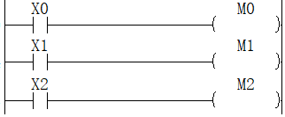
STMR/Special Function Timer
STMR
Use the 4 points starting from the device specified in (d) to perform 4 types of timer output.
-[STMR (s1) (s2) (d)]
Content, range and data type
| Parameter | Content | Range | Data type | Data type (label) |
|---|---|---|---|---|
| (s1) | Timer number used: T0 to T511 (100ms timer) | - | Device Name | ANY16 |
| (s2) | Timer setting value | 1-32767 | Signed BIN 16 bit | ANY16 |
| (d) | The start bit number of the output (occupies 4 points) | - | Bit | ANYBIT_ARRAY |
Device used
| instruction | Parameter | Devices | Index modification | Pulse extension | |||||||||||||||||||||||
|---|---|---|---|---|---|---|---|---|---|---|---|---|---|---|---|---|---|---|---|---|---|---|---|---|---|---|---|
| X | Y | M | S | SM | T(bit) | C(bit) | LC(bit) | HSC(bit) | D.b | KnX | KnY | KnM | KnS | T | C | D | R | SD | LC | HSC | K | H | E | [D] | XXP | ||
| STMR | Parameter 1 | ● | ● | ||||||||||||||||||||||||
| Parameter 2 | ● | ● | ● | ● | ● | ● | ● | ● | ● | ● | ● | ● | |||||||||||||||
| Parameter 3 | ● | ● | ● | ● | ● | ● | |||||||||||||||||||||
Features
Use the 4 points starting from the device specified in (d) to perform 4 types of timer output.
- The instruction of STMR instruction
- The setting value specified in (S2)
The blink will be in (d)+3 normally closed contact through the following program which turns on/off the STMR instruction (T10 is allocated in (s1), K100 is allocated in (s2), and M0 is allocated in (d)) Output to (d)+1, (d)+2.
The setting value of (S2) can be specified in the range of 1 to 32767 (1 to 3276.7 seconds).
Error code
| Error code | Content |
|---|---|
| 4084H | When the value specified in (s2) is less or equal to 0 |
| 4085H | When the device specified in the read application instruction (s2) and (d) exceeds the corresponding device range |
Example
Y0: When X10 changes from Off→On, Y0=On, when X10 changes from On→Off, Y0=Off after a delay of 10 seconds.
Y1: When X10 changes from On→Off, make Y1=On output once for 10 seconds.
Y2: When X10 changes from Off to On, output Y2=On once for 10
Y3: When X10 changes from Off to On, Y3=On after 10 seconds of delay. When X10 changes from On to Off, Y3=Off after 10 seconds
If the component (d)+3 is introduced into the instruction stream, the oscillator output can be easily realized (this function can also be realized by the ALT instruction), as shown in the following figure:
TTMR/Demonstration Timer
TTMR
Test the time when the TTMR instruction is ON. It is used when adjusting the timer setting time with buttons.
-[TTMR (d) (s)]
Content, range and data type
| Parameter | Content | Range | Data type | Data type (label) |
|---|---|---|---|---|
| (d) | Device for storing teaching data | - | Signed BIN 16 bit | ANY16 |
| (s) | Multiplying ratio of teaching data | 0-2 | Signed BIN 16 bit | ANY16 |
Device used
| instruction | Parameter | Devices | Index modification | Pulse extension | |||||||||||||||||||||||
|---|---|---|---|---|---|---|---|---|---|---|---|---|---|---|---|---|---|---|---|---|---|---|---|---|---|---|---|
| X | Y | M | S | SM | T(bit) | C(bit) | LC(bit) | HSC(bit) | D.b | KnX | KnY | KnM | KnS | T | C | D | R | SD | LC | HSC | K | H | E | [D] | XXP | ||
| TTMR | Parameter 1 | ● | ● | ● | ● | ● | ● | ||||||||||||||||||||
| Parameter 2 | ● | ● | ● | ● | ● | ● | ● | ● | ● | ● | ● | ● | |||||||||||||||
Features
Measure the time of the execution instruction (button) in seconds, multiply it by the magnification (10S) specified in (s) and store it in the device specified in (d).


For the time stored in (d), when the execution time is (unit: second), the actual value of (d) is as follows according to the magnification specified in (s).
| (s) | Magnification | (D) |
| K0 |
| (D) ×1 |
| K1 |
| (D)×10 |
| K2 |
| (D) ×100 |
| (s) | (d) | (d)+1 (unit: 100 milliseconds) |
| K0 (unit: second) | (d)+1 =(d)×10 | |
| K1 (unit: 100 milliseconds) | (d)+1 =(d) | |
| K2 (unit: 10 milliseconds) | (d)+1 =(d)/10 |
✎Note:
If the instruction contact turns from ON→OFF, the current value of the execution time (d)+1 is cleared, and the teaching time (d) does not change.
Occupy the device specified in the 2 teaching time (d) at the beginning. Be careful not to overlap with the device used for machine control.
Error code
| Error code | Content |
| 4084H | When the value specified in (n) exceeds the range of 0 to 2 |
| 4085H | When the device specified in read application instruction (d) and (s) exceeds the corresponding device range |
| 4086H | When the device specified in the write application instruction (d) exceeds the corresponding device range |
Example
Example 1
External IO instructions
 ARWS/Arrow Switch
ARWS
Use the arrow switches for digit movement and increase or decrease of digit values to input data instructions.
-[ARWS (s) (d1) (d2) (n)]
Content, range and data type
| Parameter | Content | Range | Data type | Data type (label) |
| (s) | The start device number that input | - | BIN16 bit | ANY_BOOL |
| (d1) | The word device number storing BCD conversion data | - | BIN16 bit | ANY_BOOL |
| (d2) | The start bit device (Y) that connect the display of the 7-segment digital tube | 0 to 9999 | BIN16 bit | ANY16_S |
| (n) | Specify the number of digits displayed by the 7-segment digital tube (Setting range: K0 to K3) | 0 to 3 | BIN16 bit | ANY16_S |
Device used
| instruction | Parameter | Devices | Index modification | Pulse extension | |||||||||||||||||||||||
| X | Y | M | S | SM | T(bit) | C(bit) | LC(bit) | HSC(bit) | D.b | KnX | KnY | KnM | KnS | T | C | D | R | SD | LC | HSC | K | H | E | [D] | XXP | ||
| ARWS | Parameter 1 | ● | ● | ● | ● | ● | ● | ● | |||||||||||||||||||
| Parameter 2 | ● | ● | ● | ● | ● | ● | |||||||||||||||||||||
| Parameter 3 | ● | ● | |||||||||||||||||||||||||
| Parameter 4 | ● | ● | |||||||||||||||||||||||||
Features
16-bit operation (ARWS). The 16-bit BIN value from 0 to 9999 is stored in D+1. For the sake of convenience, the following description is displayed in BCD conversion.
When the instruction input is ON, the ARWS instruction will operate as shown below


Display and operation part of the content

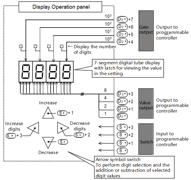
- The digit specification of n displayed by the 7-segment digital tube with BCD code
A 4-digit (103 digit) is used as an example in the following operation description, .
The action of the digit selection switch (S+2, S+3)
- The action when input S+2 with reduced digits is ON.Each time the switch is pressed, the number of digits specification is changed according to 103 →102 →101 →100 →103.
- The action when the input S+3 with increased digits is ON. Each time the switch is pressed, the number of digits specification is changed according to 103 → 100 → 101 → 102 → 103.
- The action of the LED for displaying the selected digits (D2+4 to D2+7). The specified number of digits can be displayed by LED by strobe signal D2+4 to D2+7.
- The operation of the data change switch in units of digits (S, S+1). The data is changed for the number of digits specified by the "digit selection switch" above.
- Increase the action when the input is ON. Each time the switch is pressed, the content of D1 changes according to 0→1→2→...→8→9→0→1.
- Reduce the action when the input is ON. Each time the switch is pressed, the content of D1 changes according to 0→9→8→7...1→0→9.
These contents can be displayed in the 7-segment digital tube display.
As shown above, through a series of operations, you can write the target value into D1 while viewing the 7-segment display.
✎Note:
- The setting of parameter n
Please refer to the parameter setting of SEGL (FNC 74) instruction. The setting range is 0 to 3.
- The output format of the programmable controller, please use a transistor output type programmable controller.
- About scan time (operation cycle) and display timing
- The ARWS instruction is executed synchronously with the scan time (operation cycle) of the programmable controller.
- In order to perform a series of displays, the scan time of the programmable controller needs to exceed 10ms.
- When it is less than 10ms, please use the constant scan mode and run with a scan time longer than 10ms.
- Number of occupied points of the device
- The input of the device s occupies 4 points.
- The output of the device d2 occupies 8 points.
- Restrictions on the times of the uses of instructions
Only one ARWS instruction can be used in the program.
Error code
| Error code | Content |
| 4084H | The data input in the application instruction (d1) and (d2) exceeds the specified range |
| 4085H | The output result of the read application instruction (s), (d1) and (d2) exceeds the device range |
| 4086H | The output result of the write application instruction (d1) and (d2) exceeds the device range |
Example

The corresponding hardware wiring is shown in the figure below, and the PLC should be transistor output type:

(1) The digital tube in the figure shows the value of D0. Press X10 to X13 to modify the value. The value of D0 can only be between 0 and 9999.
(2) When X20 is ON, the cursor position is thousands. Each time the back key (X12) is pressed, the specified position is switched in the order of "thousands → hundred → ten → pieces → thousand"; if the forward key (X13) is pressed, the switching sequence is reversed; the cursor position is determined by the strobe pulse signal (YO04 to YOO7) LED indication of connection.
(3) For the cursor position, each time you press the increment key (X11), the content of the position changes by 0 → 1→ 2→……8→9→0→1, and when you press the decrement key (X10), press 0 →9→8→7→…… 1→0→9 changes, the modified value takes effect immediately.