08 Motion Control
Management Function Blocks for Single-axis Motion Control
MC_POWER
MC_POWER
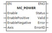
This function block is a power-on software switch for the motion control system.
Device used (only a single device can be used, and device splicing and offset are not supported)
| Instruction | Parameter | Devices | Index modification | Pulse expansion | |||||||||||||||||||||||
|---|---|---|---|---|---|---|---|---|---|---|---|---|---|---|---|---|---|---|---|---|---|---|---|---|---|---|---|
| X | Y | M | S | SM | T(bit) | C(bit) | LC(bit) | HSC(bit) | D.b | KnX | KnY | KnM | KnS | T | C | D | R | SD | LC | HSC | K | H | E | [D] | XXP | ||
| MC_POWER | Enable | ● | ● | ● | ● | ● | |||||||||||||||||||||
| EnablePositive | ● | ● | ● | ● | ● | ||||||||||||||||||||||
| EnableNegative | ● | ● | ● | ● | ● | ||||||||||||||||||||||
| Axis | |||||||||||||||||||||||||||
| Status | ● | ● | ● | ● | |||||||||||||||||||||||
| Valid | ● | ● | ● | ● | |||||||||||||||||||||||
| Error | ● | ● | ● | ● | |||||||||||||||||||||||
| ErrorID | |||||||||||||||||||||||||||
Precautions for use of devices
- LC and HSC are signed 32-bit data types;
- T, C, D, R, SD are signed 16-bit data types.
Variable Type Used
| Instruction | Parameter | Variable type | Can be empty or not | Range | Description |
|---|---|---|---|---|---|
| MC_POWER | Enable | BOOL | No | TRUE/FALSE | Enable |
| EnablePositive | BOOL | No | TRUE/FALSE | Allow motion in the positive direction | |
| EnableNegative | BOOL | No | TRUE/FALSE | Allow motion in negative direction | |
| Axis | WORD | No | 0 to 65535 | Axis number | |
| Status | BOOL | No | TRUE/FALSE | Enable status | |
| Valid | BOOL | No | TRUE/FALSE | Data valid or not | |
| Error | BOOL | No | TRUE/FALSE | Whether there is an error or not | |
| ErrorID | DWORD | No | - | [Error code] |
Function
- This function block must be enabled if an axis is to participate in motion.
- The function is as follows:
- When the Enable input is TRUE, the power to the drive is enabled, not to the function block itself;
- When the Enable input is TRUE, this function block is called. If the state of the axis is in the Disable state, then the state of the axis is switched to the state of StandStill, waiting for the motion control of the axis;
- If a fault occurs when the Enable input is TRUE, a timer function block and an AND logic function can make the state of its axis remain at FAlSE. It indicates that there is a fault at the hardware level;
- If the PLC power supply fails during the motion, the state of the axis will switch to the ErrorStop state;
- The input signals EnablePositive and EnableNegative are level controlled. When they are TRUE, axis motion in the positive and negative directions are allowed. Two input signals can be set at the same time, indicating that the allowed motion direction can be either positive or negative;
- Each axis can only have one MC_POWER function block for powering up the axis. If multiple MC_POWER control the same axis, the last function block is valid;
- The Status output signal indicates the status of the driver power supply, and 1 means power on; 0 means not power on. It is also not a simulated value if the axis drive is a simulated axis. Busy is the operating status of the function block, 1 means busy; 0 means idle. 0 means uncontrolled. Valid indicates whether the output signal of the function block is valid, and 1 means the output signal is valid; 0 means the output signal is invalid. Error indicates whether the function block is faulty, and 1 means faulty; 0 means no fault. ErrorID is the error code, and when a function block fault occurs, there are 16 digits indicating the fault information.
Precautions
- When any error occurs when the axis is enabled, it will be fed back through Error and ErrorID;
- The PDO parameters of servo axis bound to the axis must have control word, status word, target position and current position.
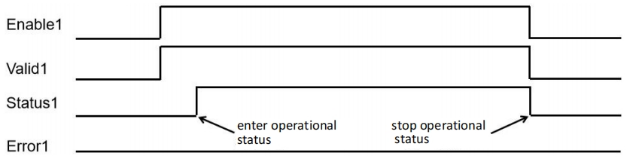
Sequence diagram
- When using a MC_POWER instruction and axis enables normally, sequence diagram is as follows:
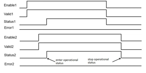
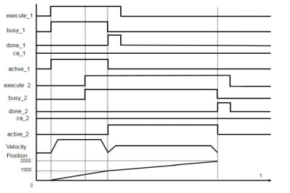
- When axis uses two MC_POWER instructions and axis enables normally, sequence diagram is as follows:
MC_READSTATUS
MC_READSTATUS
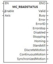
This function block is used to read the status of the controlled axis.
Device used (only a single device can be used, and device splicing and offset are not supported)
| Instruction | Parameter | Devices | Index modification | Pulse expansion | |||||||||||||||||||||||
|---|---|---|---|---|---|---|---|---|---|---|---|---|---|---|---|---|---|---|---|---|---|---|---|---|---|---|---|
| X | Y | M | S | SM | T(bit) | C(bit) | LC(bit) | HSC(bit) | D.b | KnX | KnY | KnM | KnS | T | C | D | R | SD | LC | HSC | K | H | E | [D] | XXP | ||
| MC_READSTATUS | Enable | ● | ● | ● | ● | ● | |||||||||||||||||||||
| Axis | |||||||||||||||||||||||||||
| Valid | ● | ● | ● | ● | |||||||||||||||||||||||
| Busy | ● | ● | ● | ● | |||||||||||||||||||||||
| Error | ● | ● | ● | ● | |||||||||||||||||||||||
| ErrorID | |||||||||||||||||||||||||||
| Errorstop | ● | ● | ● | ● | |||||||||||||||||||||||
| Disabled | ● | ● | ● | ● | |||||||||||||||||||||||
| Stopping | ● | ● | ● | ● | |||||||||||||||||||||||
| Homing | ● | ● | ● | ● | |||||||||||||||||||||||
| Standstill | ● | ● | ● | ● | |||||||||||||||||||||||
| DiscreteMotion | ● | ● | ● | ● | |||||||||||||||||||||||
| ContinuousMotion | ● | ● | ● | ● | |||||||||||||||||||||||
| SynchronizedMotion | ● | ● | ● | ● | |||||||||||||||||||||||
Precautions for use of devices
- LC and HSC are signed 32-bit data types;
- T, C, D, R and SD are signed 16-bit data types;
Variable Type Used
| Instruction | Parameter | Variable type | Can be empty or not | Range | Description |
|---|---|---|---|---|---|
| MC_READSTATUS | Enable | BOOL | No | TRUE/FALSE | Enable |
| Axis | WORD | No | 0 to 65535 | Axis number | |
| Valid | BOOL | No | TRUE/FALSE | Output valid or not | |
| Busy | BOOL | No | TRUE/FALSE | Busy sign | |
| Error | BOOL | No | TRUE/FALSE | Whether there is an error or not | |
| ErrorID | DWORD | No | - | Error code | |
| Errorstop | BOOL | No | TRUE/FALSE | Error stop sign | |
| Disabled | BOOL | No | TRUE/FALSE | Inactive sign | |
| Stopping | BOOL | No | TRUE/FALSE | Stopping sign | |
| Homing | BOOL | No | TRUE/FALSE | Homing sign | |
| Standstill | BOOL | No | TRUE/FALSE | Static sign | |
| DiscreteMotion | BOOL | No | TRUE/FALSE | Discontinuous motion sign | |
| ContinuousMotion | BOOL | No | TRUE/FALSE | Continuous motion sign | |
| SynchronizedMotion | BOOL | No | TRUE/FALSE | Synchronized motion sign |
Function
- It is used to read the status of the controlled axis, corresponding to the single-axis SynchronizedMotion, ContinuousMotion, DiscreteMotion, Stopping, Errorstop, Homing, Standstill and Disabled;
- When the MC_ReadStatus function block input Enable is TRUE, the status of the axis is periodically updated.
Precautions
- This function block is not available when the axis does not exist.
Sequence diagram
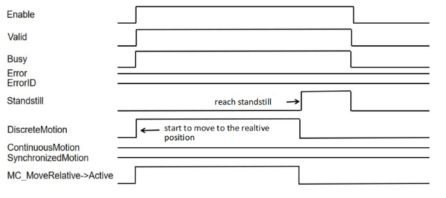
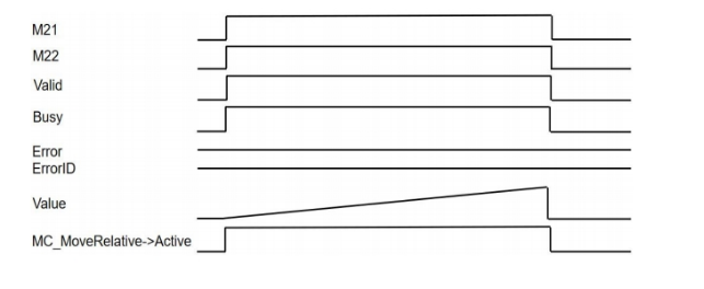
When using MC_READSTATUS with MC_MOVERELATIVE instruction together and axis enables normally, sequence diagram is as follows:
MC_READMOTIONSTATE
MC_READMOTIONSTATE
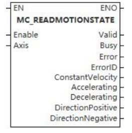
This function block is used to read the motion status of the controlled axis, including constant speed, acceleration, deceleration, positive direction and negative direction.
Device used (only a single device can be used, and device splicing and offset are not supported)
| Instruction | Parameter | Devices | Index modification | Pulse expansion | |||||||||||||||||||||||
|---|---|---|---|---|---|---|---|---|---|---|---|---|---|---|---|---|---|---|---|---|---|---|---|---|---|---|---|
| X | Y | M | S | SM | T(bit) | C(bit) | LC(bit) | HSC(bit) | D.b | KnX | KnY | KnM | KnS | T | C | D | R | SD | LC | HSC | K | H | E | [D] | XXP | ||
| MC_READMOTIONSTATE | Enable | ● | ● | ● | ● | ● | |||||||||||||||||||||
| Axis | ● | ● | ● | ● | |||||||||||||||||||||||
| Valid | ● | ● | ● | ● | |||||||||||||||||||||||
| Busy | ● | ● | ● | ● | |||||||||||||||||||||||
| Error | |||||||||||||||||||||||||||
| ErrorID | |||||||||||||||||||||||||||
| ConstantVelocity | ● | ● | ● | ● | |||||||||||||||||||||||
| Accelerating | ● | ● | ● | ● | |||||||||||||||||||||||
| Decelerating | ● | ● | ● | ● | |||||||||||||||||||||||
| DirectionPositive | ● | ● | ● | ● | |||||||||||||||||||||||
| DirectionNegative | ● | ● | ● | ● | |||||||||||||||||||||||
Precautions for use of devices
- LC and HSC are signed 32-bit data types;
- T, C, D, R and SD are signed 16-bit data types;
Variable Type Used
| Instruction | Parameter | Variable type | Can be empty or not | Range | Description |
|---|---|---|---|---|---|
| MC_READMOTIONSTATE | Enable | BOOL | No | TRUE/FALSE | Enable |
| Axis | WORD | No | 0 to 65535 | Axis number | |
| Valid | BOOL | No | TRUE/FALSE | Output valid or not | |
| Busy | BOOL | No | TRUE/FALSE | Busy sign | |
| Error | BOOL | No | TRUE/FALSE | Whether there is an error or not | |
| ErrorID | DWORD | No | - | Error code | |
| ConstantVelocity | BOOL | No | TRUE/FALSE | Constant velocity | |
| Accelerating | BOOL | No | TRUE/FALSE | Accelerating | |
| Decelerating | BOOL | No | TRUE/FALSE | Decelerating | |
| DirectionPositive | BOOL | No | TRUE/FALSE | Positive direction | |
| DirectionNegative | BOOL | No | TRUE/FALSE | Negative direction |
Function
- Used to read the motion status of the controlled axis, including constant speed, acceleration, deceleration, positive direction and negative direction;
- When the MC_ReadStatus function block input Enable is TRUE, the status of the axis is periodically updated.
Precautions
- This function block is not available when the axis does not exist.
Error code
| Error code | Content |
|---|---|
| 4084H | Data beyond the specifiable range was entered. |
Sequence diagram
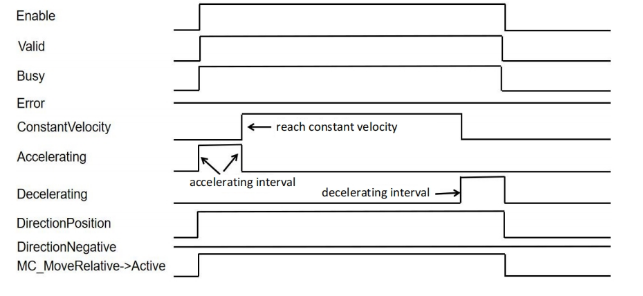
- When using MC_READMOTIONSTATE with MC_MOVERELATIVE instruction together and axis enables normally, sequence diagram is as follows:
MC_READAXISERROR
MC_READAXISERROR
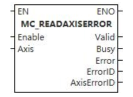
The function block provides fault information about the axis.
Device used (only a single device can be used, and device splicing and offset are not supported)
| Instruction | Parameter | Devices | Index modification | Pulse expansion | |||||||||||||||||||||||
|---|---|---|---|---|---|---|---|---|---|---|---|---|---|---|---|---|---|---|---|---|---|---|---|---|---|---|---|
| X | Y | M | S | SM | T(bit) | C(bit) | LC(bit) | HSC(bit) | D.b | KnX | KnY | KnM | KnS | T | C | D | R | SD | LC | HSC | K | H | E | [D] | XXP | ||
| MC_READAXISERROR | Enable | ● | ● | ● | ● | ● | |||||||||||||||||||||
| Axis | |||||||||||||||||||||||||||
| Valid | ● | ● | ● | ● | |||||||||||||||||||||||
| Busy | ● | ● | ● | ● | |||||||||||||||||||||||
| Error | ● | ● | ● | ● | |||||||||||||||||||||||
| ErrorID | |||||||||||||||||||||||||||
| AxisErrorID | |||||||||||||||||||||||||||
Precautions for use of devices
- LC and HSC are signed 32-bit data types;
- T, C, D, R and SD are signed 16-bit data types;
Variable Type Used
| Instruction | Parameter | Variable type | Can be empty or not | Range | Description |
|---|---|---|---|---|---|
| MC_READAXISERROR | Enable | BOOL | No | TRUE/FALSE | Enable |
| Axis | WORD | No | 0 to 65535 | Axis number | |
| Valid | BOOL | No | TRUE/FALSE | Output valid or not | |
| Busy | BOOL | No | TRUE/FALSE | Busy sign | |
| Error | BOOL | No | TRUE/FALSE | Whether there is an error or not | |
| ErrorID | DWORD | No | - | Error code | |
| AxisErrorID | DWORD | No | - | Axis error code |
Function
- The function block provides fault information for the axis. Typically, you can connect the axis status ErrorStop output of the MC_READSTATUS function block to the Enable input end of MC_READAXISERROR, so that the fault code of the axis can be obtained from AxisErrorID. You can also get the fault code from ErrorID.
Precautions
- This function block is not available when the axis does not exist.
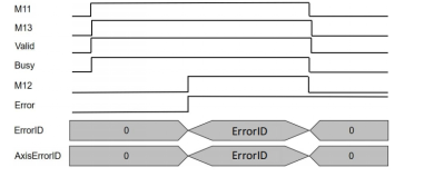
Sequence diagram
- When using MC_READAXISINFO with MC_POWER and MC_MOVERELATIVE instructions together and axis enables normally, in which MC_POWER→EnablePosition is FALSE and MC_POWER→EnableNegative is TRUE, sequence diagram is as follows:
MC_READAXISINFO
MC_READAXISINFO
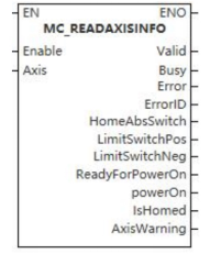
The function block is used to provide information about the axis.
Device used (only a single device can be used, and device splicing and offset are not supported)
| Instruction | Parameter | Devices | Index modification | Pulse expansion | |||||||||||||||||||||||
| X | Y | M | S | SM | T(bit) | C(bit) | LC(bit) | HSC(bit) | D.b | KnX | KnY | KnM | KnS | T | C | D | R | SD | LC | HSC | K | H | E | [D] | XXP | ||
| MC_READAXISINFO | Enable | ● | ● | ● | ● | ● | |||||||||||||||||||||
| Axis | |||||||||||||||||||||||||||
| Valid | ● | ● | ● | ● | |||||||||||||||||||||||
| Busy | ● | ● | ● | ● | |||||||||||||||||||||||
| Error | ● | ● | ● | ● | |||||||||||||||||||||||
| ErrorID | |||||||||||||||||||||||||||
| HomeAbsSwitch | ● | ● | ● | ● | |||||||||||||||||||||||
| LimitSwitchPos | ● | ● | ● | ● | |||||||||||||||||||||||
| LimitSwitchNeg | ● | ● | ● | ● | |||||||||||||||||||||||
| ReadyForPowerOn | ● | ● | ● | ● | |||||||||||||||||||||||
| powerOn | ● | ● | ● | ● | |||||||||||||||||||||||
| IsHomed | ● | ● | ● | ● | |||||||||||||||||||||||
| AxisWarning | ● | ● | ● | ● | |||||||||||||||||||||||
Precautions for use of devices
- LC and HSC are signed 32-bit data types;
- T, C, D, R and SD are signed 16-bit data types.
Variable Type Used
| Instruction | Parameter | Variable type | Can be empty or not | Range | Description |
|---|---|---|---|---|---|
| MC_READAXISINFO | Enable | BOOL | No | TRUE/FALSE | Enable |
| Axis | WORD | No | 0 to 65535 | Axis number | |
| Valid | BOOL | No | TRUE/FALSE | Output valid or not | |
| Busy | BOOL | No | TRUE/FALSE | Busy sign | |
| Error | BOOL | No | TRUE/FALSE | Whether there is an error or not | |
| ErrorID | DWORD | No | - | Error code | |
| HomeAbsSwitch | BOOL | No | TRUE/FALSE | Homing absolute position switch | |
| LimitSwitchPos | BOOl | No | TRUE/FALSE | Positive limit switch | |
| LimitSwitchNeg | BOOl | No | TRUE/FALSE | Negative limit switch | |
| ReadyForPowerOn | BOOl | No | TRUE/FALSE | Ready to enable | |
| powerOn | BOOl | No | TRUE/FALSE | Enable | |
| IsHomed | BOOl | No | TRUE/FALSE | Homing successful | |
| AxisWarning | BOOl | No | TRUE/FALSE | Axis warning |
Function
- It is used to provide information about the axis, including the information about the absolute position switch back to the origin, the status information of the positive and negative limit switches, the power-on switch of the function block, and whether the axis has warnings. Generally, the output PowerOn of the MC_READAXISINFO function block can be used as the execution input of the motion control function block. For example, if the Enable of the power-on switch MC_POWER is shared with the MC_MOVEABSOLUTE function block, because the MC_MOVEABSOLUTE function block is edge triggered, and the execution of the MC_POWER function block takes a certain time, only when PowerOn is set can the actual output of MC_POWER be deemed to be powered-on so that the output PowerOn of MC_READAXISINFO is often connected to the Execute end of MC_MOVEABSOLUTE function block to ensure the edge trigger of MC_MOVEABSOLUTE function block. The Enable of the MC_READAXISINFO function block can share an input signal with the MC_POWER function block.
Precautions
- This function block is not available when the axis does not exist.
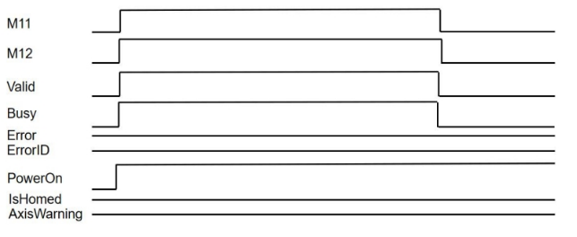
Sequence diagram
- When using MC_READAXISINFO with MC_POWER instruction together and axis enables normally, sequence diagram is as follows:
MC_READPARAMETER
MC_READPARAMETER
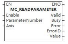
This function block is used to read axis parameters.
Device used (only a single device can be used, and device splicing and offset are not supported)
| Instruction | Parameter | Devices | Index modification | Pulse expansion | |||||||||||||||||||||||
|---|---|---|---|---|---|---|---|---|---|---|---|---|---|---|---|---|---|---|---|---|---|---|---|---|---|---|---|
| X | Y | M | S | SM | T(bit) | C(bit) | LC(bit) | HSC(bit) | D.b | KnX | KnY | KnM | KnS | T | C | D | R | SD | LC | HSC | K | H | E | [D] | XXP | ||
| MC_READPARAMETER | Enable | ● | ● | ● | ● | ● | |||||||||||||||||||||
| ParameterNumber | ● | ● | ● | ● | ● | ||||||||||||||||||||||
| Axis | |||||||||||||||||||||||||||
| Valid | ● | ● | ● | ● | |||||||||||||||||||||||
| Busy | ● | ● | ● | ● | |||||||||||||||||||||||
| Error | ● | ● | ● | ● | |||||||||||||||||||||||
| ErrorID | |||||||||||||||||||||||||||
| Value | |||||||||||||||||||||||||||
Precautions for use of devices
- LC and HSC are signed 32-bit data types;
- T, C, D, R and SD are signed 16-bit data types.
Variable Type Used
| Instruction | Parameter | Variable type | Can be empty or not | Range | Description |
|---|---|---|---|---|---|
| MC_READPARAMETER | Enable | BOOL | No | TRUE/FALSE | Enable |
| ParameterNumber | INT | No | 1 to 17 | Parameter number | |
| Axis | WORD | No | 0 to 65535 | Axis number | |
| Valid | BOOL | No | TRUE/FALSE | Output valid or not | |
| Busy | BOOL | No | TRUE/FALSE | Busy sign | |
| Error | BOOL | No | TRUE/FALSE | Whether there is an error or not | |
| ErrorID | DWORD | No | - | Error code | |
| Value | LREAL | No | - | Axis parameter value |
Function
- Used to read axis parameters, as shown in following table.
| Parameter number PN | Parameter name | Data type | B/E | R/W | Notes |
|---|---|---|---|---|---|
| 1 | InstructionedPosition | REAL | B | R | Instruction position |
| 2 | SWLimitPos | REAL | E | R/W | Position of positive software limit switch |
| 3 | SWLimitNeg | REAL | E | R/W | Positive of negative software limit switch |
| 4 | EnableLimitPos | BOOL | E | R/W | Enable positive software limit switch |
| 5 | EnableLimitNeg | BOOL | E | R/W | Enable negative software limit switch |
| 6 | EnablePosLagMonitoring | BOOL | E | R/W | Enable position lag monitoring |
| 7 | MaxPositionLag | REAL | E | R/W | Maximum position lag |
| 8 | MaxVelocitySystem | REAL | E | R | Maximum allowable axial velocity in motion system |
| 9 | MaxVelocityAppl | REAL | B | R/W | Maximum allowable axial velocity in application |
| 10 | ActualVelocity | REAL | B | R | Actual velocity |
| 11 | InstructionedVelocity | REAL | B | R | Instructioned velocity |
| 12 | MaxAccelerationSystem | REAL | E | R | Maximum allowable axial acceleration in motion system |
| 13 | MaxAccelerationAppl | REAL | E | R/W | Maximum allowable axial acceleration in application |
| 14 | MaxDecelerationSystem | REAL | E | R | Maximum allowable axial deceleration in motion system |
| 15 | MaxDecelerationAppl | REAL | E | R/W | Maximum allowable axial deceleration in application |
| 16 | MaxJerkSystem | REAL | E | R | Maximum allowable axial jerk in motion system |
| 17 | MaxJerkAppl | REAL | E | R/W | Maximum allowable axial jerk in application system |
Precautions
- This function block is not available when the axis does not exist.
Error code
| Error code | Content |
|---|---|
| 4084H | Data beyond the specifiable range was entered. |
Sequence diagram
- When using MC_READPARAMETER with MC_MOVERELATIVE instruction together, in which ParameterNumber=1, and axis enables normally, sequence diagram is as follows:
MC_READBOOLPARAMETER
MC_READBOOLPARAMETER
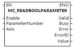
This function block is used to read axis Boolean parameters.
Device used (only a single device can be used, and device splicing and offset are not supported)
| Instruction | Parameter | Devices | Index modification | Pulse expansion | |||||||||||||||||||||||
|---|---|---|---|---|---|---|---|---|---|---|---|---|---|---|---|---|---|---|---|---|---|---|---|---|---|---|---|
| X | Y | M | S | SM | T(bit) | C(bit) | LC(bit) | HSC(bit) | D.b | KnX | KnY | KnM | KnS | T | C | D | R | SD | LC | HSC | K | H | E | [D] | XXP | ||
| MC_READBOOLPARAMETER | Enable | ● | ● | ● | ● | ● | |||||||||||||||||||||
| ParameterNumber | ● | ● | ● | ● | ● | ||||||||||||||||||||||
| Axis | |||||||||||||||||||||||||||
| Valid | ● | ● | ● | ● | |||||||||||||||||||||||
| Busy | ● | ● | ● | ● | |||||||||||||||||||||||
| Error | ● | ● | ● | ● | |||||||||||||||||||||||
| ErrorID | |||||||||||||||||||||||||||
| Value | ● | ● | ● | ● | |||||||||||||||||||||||
Precautions for use of devices
- LC and HSC are signed 32-bit data types;
- T, C, D, R and SD are signed 16-bit data types;
Variable Type Used
| Instruction | Parameter | Variable type | Can be empty or not | Range | Description |
|---|---|---|---|---|---|
| MC_READBOOLPARAMETER | Enable | BOOL | No | TRUE/FALSE | Enable |
| ParameterNumber | INT | No | 1 to 17 | Parameter number | |
| Axis | WORD | No | 0 to 65535 | Axis number | |
| Valid | BOOL | No | TRUE/FALSE | Output valid or not | |
| Busy | BOOL | No | TRUE/FALSE | Busy sign | |
| Error | BOOL | No | TRUE/FALSE | Whether there is an error or not | |
| ErrorID | DWORD | No | - | Error code | |
| Value | BOOL | No | TRUE/FALSE | Axis parameter |
Function
- Used to read axis Boolean parameters, as shown in following table.
| Parameter number PN | Parameter name | Data type | B/E | R/W | Notes |
|---|---|---|---|---|---|
| 1 | InstructionedPosition | REAL | B | R | Instruction position |
| 2 | SWLimitPos | REAL | E | R/W | Position of positive software limit switch |
| 3 | SWLimitNeg | REAL | E | R/W | Positive of negative software limit switch |
| 4 | EnableLimitPos | BOOL | E | R/W | Enable positive software limit switch |
| 5 | EnableLimitNeg | BOOL | E | R/W | Enable negative software limit switch |
| 6 | EnablePosLagMonitoring | BOOL | E | R/W | Enable position lag monitoring |
| 7 | MaxPositionLag | REAL | E | R/W | Maximum position lag |
| 8 | MaxVelocitySystem | REAL | E | R | Maximum allowable axial velocity in motion system |
| 9 | MaxVelocityAppl | REAL | B | R/W | Maximum allowable axial velocity in application |
| 10 | ActualVelocity | REAL | B | R | Actual velocity |
| 11 | InstructionedVelocity | REAL | B | R | Instructioned velocity |
| 12 | MaxAccelerationSystem | REAL | E | R | Maximum allowable axial acceleration in motion system |
| 13 | MaxAccelerationAppl | REAL | E | R/W | Maximum allowable axial acceleration in application |
| 14 | MaxDecelerationSystem | REAL | E | R | Maximum allowable axial deceleration in motion system |
| 15 | MaxDecelerationAppl | REAL | E | R/W | Maximum allowable axial deceleration in application |
| 16 | MaxJerkSystem | REAL | E | R | Maximum allowable axial jerk in motion system |
| 17 | MaxJerkAppl | REAL | E | R/W | Maximum allowable axial jerk in application system |
Precautions
- This function block is not available when the axis does not exist.
Error code
| Error code | Content |
|---|---|
| 4084H | Data beyond the specifiable range was entered. |
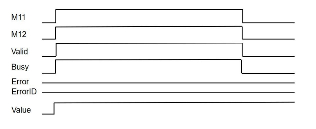
Sequence diagram
MC_READACTUALVELOCITY
MC_READACTUALVELOCITY
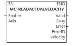
This function block is used to read the actual velocity of the controlled axis.
Device used (only a single device can be used, and device splicing and offset are not supported)
| Instruction | Parameter | Devices | Index modification | Pulse expansion | |||||||||||||||||||||||
|---|---|---|---|---|---|---|---|---|---|---|---|---|---|---|---|---|---|---|---|---|---|---|---|---|---|---|---|
| X | Y | M | S | SM | T(bit) | C(bit) | LC(bit) | HSC(bit) | D.b | KnX | KnY | KnM | KnS | T | C | D | R | SD | LC | HSC | K | H | E | [D] | XXP | ||
| MC_READACTUALVELOCITY | Enable | ● | ● | ● | ● | ● | |||||||||||||||||||||
| Axis | |||||||||||||||||||||||||||
| Valid | ● | ● | ● | ● | |||||||||||||||||||||||
| Busy | ● | ● | ● | ● | |||||||||||||||||||||||
| Error | ● | ● | ● | ● | |||||||||||||||||||||||
| ErrorID | |||||||||||||||||||||||||||
| Velocity | |||||||||||||||||||||||||||
Precautions for use of devices
- LC and HSC are signed 32-bit data types;
- T, C, D, R and SD are signed 16-bit data types.
Variable Type Used
| Instruction | Parameter | Variable type | Can be empty or not | Range | Description |
|---|---|---|---|---|---|
| MC_READACTUALVELOCITY | Enable | BOOL | No | TRUE/FALSE | Enable |
| Axis | WORD | No | 0 to 65535 | Axis number | |
| Valid | BOOL | No | TRUE/FALSE | Output valid or not | |
| Busy | BOOL | No | TRUE/FALSE | Busy sign | |
| Error | BOOL | No | TRUE/FALSE | Whether there is an error or not | |
| ErrorID | DWORD | No | - | Error code | |
| Velocity | LREAL | No | - | Actual velocity |
Function
- When the function block’s Enable is set, the MC_READACTUALVELOCITY output returns the actual velocity of the controlled single axis.
Precautions
- This function block is not available when the axis does not exist;
- When the function block's Enable is reset, the output value loses its validity, and the Valid output is reset.
Sequence diagram
MC_READACTUALPOSITION
MC_READACTUALPOSITION
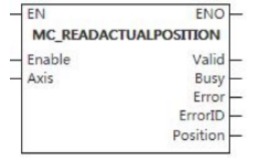
This function block is used to read the actual absolute position of the axis.
Device used (only a single device can be used, and device splicing and offset are not supported)
| Instruction | Parameter | Devices | Index modification | Pulse expansion | |||||||||||||||||||||||
|---|---|---|---|---|---|---|---|---|---|---|---|---|---|---|---|---|---|---|---|---|---|---|---|---|---|---|---|
| X | Y | M | S | SM | T(bit) | C(bit) | LC(bit) | HSC(bit) | D.b | KnX | KnY | KnM | KnS | T | C | D | R | SD | LC | HSC | K | H | E | [D] | XXP | ||
| MC_READACTUALPOSITION | Enable | ● | ● | ● | ● | ● | |||||||||||||||||||||
| Axis | |||||||||||||||||||||||||||
| Valid | ● | ● | ● | ● | |||||||||||||||||||||||
| Busy | ● | ● | ● | ● | |||||||||||||||||||||||
| Error | ● | ● | ● | ● | |||||||||||||||||||||||
| ErrorID | |||||||||||||||||||||||||||
| Position | |||||||||||||||||||||||||||
Precautions for use of devices
- LC and HSC are signed 32-bit data types;
- T, C, D, R and SD are signed 16-bit data types;
Variable Type Used
| Instruction | Parameter | Variable type | Can be empty or not | Range | Description |
|---|---|---|---|---|---|
| MC_READACTUALPOSITION | Enable | BOOL | No | TRUE/FALSE | Enable |
| Axis | WORD | No | 0 to 65535 | Axis number | |
| Valid | BOOL | No | TRUE/FALSE | Output valid or not | |
| Busy | BOOL | No | TRUE/FALSE | Busy sign | |
| Error | BOOL | No | TRUE/FALSE | Whether there is an error or not | |
| ErrorID | DWORD | No | - | Error code | |
| Position | LREAL | No | - | Actual absolute position |
Function
- When the function block’s Enable is set, the MC_READACTUALPOSITION output returns the actual absolute position of the controlled single axis.
Precautions
- This function block is not available when the axis does not exist;
- 0x6064 should be configured in the bus axis, otherwise it is invalid;
- When the function block's Enable is reset, the output value loses its validity, and the Valid output is reset.
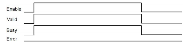
Sequence diagram
MC_RESET
MC_RESET
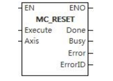
This function block is used for clearing the faults of the controlled axis.
Device used (only a single device can be used, and device splicing and offset are not supported)
| Instruction | Parameter | Devices | Index modification | Pulse expansion | |||||||||||||||||||||||
|---|---|---|---|---|---|---|---|---|---|---|---|---|---|---|---|---|---|---|---|---|---|---|---|---|---|---|---|
| X | Y | M | S | SM | T(bit) | C(bit) | LC(bit) | HSC(bit) | D.b | KnX | KnY | KnM | KnS | T | C | D | R | SD | LC | HSC | K | H | E | [D] | XXP | ||
| MC_RESET | Execute | ● | ● | ● | ● | ● | |||||||||||||||||||||
| Axis | |||||||||||||||||||||||||||
| Done | ● | ● | ● | ● | |||||||||||||||||||||||
| Busy | ● | ● | ● | ● | |||||||||||||||||||||||
| Error | ● | ● | ● | ● | |||||||||||||||||||||||
| ErrorID | |||||||||||||||||||||||||||
Precautions for use of devices
- LC and HSC are signed 32-bit data types;
- T, C, D, R and SD are signed 16-bit data types;
Variable Type Used
| Instruction | Parameter | Variable type | Can be empty or not | Range | Description |
|---|---|---|---|---|---|
| MC_RESET | Execute | BOOL | No | TRUE/FALSE | Enable |
| Axis | WORD | No | 0 to 65535 | Axis number | |
| Done | BOOL | No | TRUE/FALSE | Completion sign | |
| Busy | BOOL | No | TRUE/FALSE | Busy sign | |
| Error | BOOL | No | TRUE/FALSE | Whether there is an error or not | |
| ErrorID | DWORD | No | - | Error code |
Function
- When the Execute input signal rises, it is used to clear the fault of the controlled axis. These faults include axis faults and drive side faults. If the drive itself fails, the reset of the drive failure should be carried out first. These fault treatments do not cause the motion of the controlled axis.
Precautions
- This function block is not available when the axis does not exist.
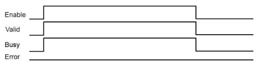
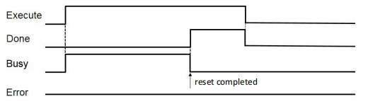
Sequence diagram
- In the case of axis failure, call MC_RESET instruction and reset successfully, sequence diagram is as follows:
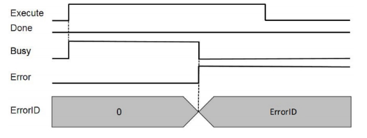
- When driver cannot be reset, sequence diagram is as follows:
MC_SETPOSITION
MC_SETPOSITION
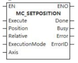
This function block is used to set the position (absolute position or relative position) of the controlled axis.
Device used (only a single device can be used, and device splicing and offset are not supported)
| Instruction | Parameter | Devices | Index modification | Pulse expansion | |||||||||||||||||||||||
|---|---|---|---|---|---|---|---|---|---|---|---|---|---|---|---|---|---|---|---|---|---|---|---|---|---|---|---|
| X | Y | M | S | SM | T(bit) | C(bit) | LC(bit) | HSC(bit) | D.b | KnX | KnY | KnM | KnS | T | C | D | R | SD | LC | HSC | K | H | E | [D] | XXP | ||
| MC_SETPOSITION | Execute | ● | ● | ● | ● | ● | |||||||||||||||||||||
| Position | |||||||||||||||||||||||||||
| Relative | ● | ● | ● | ● | ● | ||||||||||||||||||||||
| Execution Mode | |||||||||||||||||||||||||||
| Axis | |||||||||||||||||||||||||||
| Done | ● | ● | ● | ● | |||||||||||||||||||||||
| Busy | ● | ● | ● | ● | |||||||||||||||||||||||
| Error | ● | ● | ● | ● | |||||||||||||||||||||||
| ErrorID | |||||||||||||||||||||||||||
Precautions for use of devices
- LC and HSC are signed 32-bit data types;
- T, C, D, R and SD are signed 16-bit data types;
Variable Type Used
| Instruction | Parameter | Variable type | Can be empty or not | Range | Description |
|---|---|---|---|---|---|
| MC_SETPOSITION | Execute | BOOL | No | TRUE/FALSE | Enable |
| Position | LREAL | No | -9999999.00~9999999.00 | Position | |
| Relative | BOOL | No | TRUE/FALSE | Set relative position or absolute position | |
| Execution Mode | WORD | No | 0 to 2 | Operation mode | |
| Axis | WORD | No | 0 to 65535 | Axis number | |
| Done | BOOL | No | TRUE/FALSE | Completion sign | |
| Busy | BOOL | No | TRUE/FALSE | Busy sign | |
| Error | BOOL | No | TRUE/FALSE | Whether there is an error or not | |
| ErrorID | DWORD | No | - | Error code |
Function
- MC_SETPOSITION function block is used to set the position (absolute position or relative position) of the controlled axis. It controls the set position and the actual position of the axis by moving the coordinate system of the coordinate system, so that they have the same value without causing motion, and obtains the same tracking error by re-calibration. This function block can be used for examples in reference situations;
- At present, this command does not support triggering when the axis is in motion.
Precautions
- This function block is not available when the axis does not exist.
Motion Function Blocks for Single-axis Motion Control
MC_STOP
MC_STOP
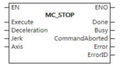
This function block is used to change the state of the controlled axis to the deceleration stopping state.
Device used (only a single device can be used, and device splicing and offset are not supported)
| Instruction | Parameter | Devices | Index modification | Pulse expansion | |||||||||||||||||||||||
|---|---|---|---|---|---|---|---|---|---|---|---|---|---|---|---|---|---|---|---|---|---|---|---|---|---|---|---|
| X | Y | M | S | SM | T(bit) | C(bit) | LC(bit) | HSC(bit) | D.b | KnX | KnY | KnM | KnS | T | C | D | R | SD | LC | HSC | K | H | E | [D] | XXP | ||
| MC_STOP | Execute | ● | ● | ● | ● | ● | |||||||||||||||||||||
| Deceleration | |||||||||||||||||||||||||||
| Jerk | |||||||||||||||||||||||||||
| Axis | |||||||||||||||||||||||||||
| Done | ● | ● | ● | ● | |||||||||||||||||||||||
| Busy | ● | ● | ● | ● | |||||||||||||||||||||||
| InstructionAborted | ● | ● | ● | ● | |||||||||||||||||||||||
| Error | ● | ● | ● | ● | |||||||||||||||||||||||
| ErrorID | |||||||||||||||||||||||||||
Precautions for use of devices
- LC and HSC are signed 32-bit data types;
- T, C, D, R and SD are signed 16-bit data types.
Variable Type Used
| Instruction | Parameter | Variable type | Can be empty or not | Range | Description |
|---|---|---|---|---|---|
| MC_STOP | Execute | BOOL | No | TRUE/FALSE | Enable |
| Deceleration | LREAL | No | 0 to 9999999.00 | Deceleration | |
| Jerk | LREAL | No | 0 to 9999999.00 | Jerk | |
| Axis | WORD | No | 0 to 65535 | Axis number | |
| Done | BOOL | No | TRUE/FALSE | Completion sign | |
| Busy | BOOL | No | TRUE/FALSE | Busy sign | |
| InstructionAborted | BOOL | No | TRUE/FALSE | Aborted sign | |
| Error | BOOL | No | TRUE/FALSE | Whether there is an error or not | |
| ErrorID | DWORD | No | - | Error code |
Function
- This function block is used to change the state of the controlled axis to the deceleration stopping state. When the rising edge of the input Execute signal triggers the function block, the controlled axis decelerates with the output Decelerate value and the axis motion stops.
Precautions
- This function block is not available when the axis does not exist.
Error code
| Error code | Content |
|---|---|
| 4084H | Data beyond the specifiable range was entered. |
Sequence diagram
- When the call is located, trigger MC_STOP instruction and sequence diagram is as follows:
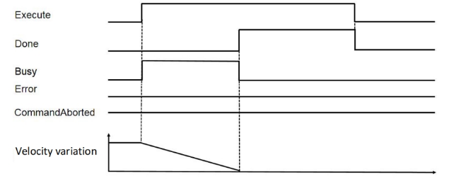
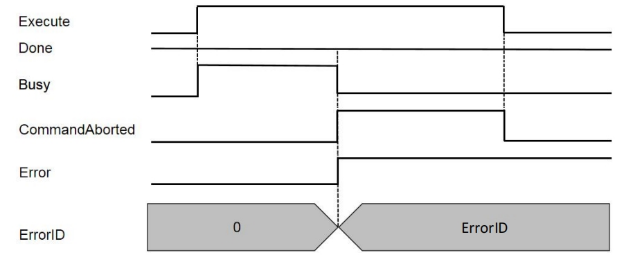
- When driver fails during the instruction running, sequence diagram is as follows:
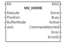
MC_HOME
MC_HOME
This function block is used to change the state of the controlled axis to the origin state.
Device used (only a single device can be used, and device splicing and offset are not supported)
| Instruction | Parameter | Devices | Index modification | Pulse expansion | |||||||||||||||||||||||
|---|---|---|---|---|---|---|---|---|---|---|---|---|---|---|---|---|---|---|---|---|---|---|---|---|---|---|---|
| X | Y | M | S | SM | T(bit) | C(bit) | LC(bit) | HSC(bit) | D.b | KnX | KnY | KnM | KnS | T | C | D | R | SD | LC | HSC | K | H | E | [D] | XXP | ||
| MC_HMOE | Execute | ● | ● | ● | ● | ● | |||||||||||||||||||||
| Position | |||||||||||||||||||||||||||
| BufferMode | |||||||||||||||||||||||||||
| Axis | |||||||||||||||||||||||||||
| Done | ● | ● | ● | ● | |||||||||||||||||||||||
| Busy | ● | ● | ● | ● | |||||||||||||||||||||||
| Active | ● | ● | ● | ● | |||||||||||||||||||||||
| InstructionAborted | ● | ● | ● | ● | |||||||||||||||||||||||
| Error | ● | ● | ● | ● | |||||||||||||||||||||||
| ErrorID | |||||||||||||||||||||||||||
Precautions for use of devices
- LC and HSC are signed 32-bit data types;
- T, C, D, R and SD are signed 16-bit data types.
Variable Type Used
| Instruction | Parameter | Variable type | Can be empty or not | Range | Description |
|---|---|---|---|---|---|
| MC_HOME | Execute | BOOL | No | TRUE/FALSE | Enable |
| Position | LREAL | No | 0 to 9999999.00 | Position | |
| BufferMode | WORD | No | 0 to 5 | Mode selection | |
| Axis | WORD | No | 0 to 65535 | Axis number | |
| Done | BOOL | No | TRUE/FALSE | Completion sign | |
| Busy | BOOL | No | TRUE/FALSE | Busy sign | |
| Active | BOOL | Yes | TRUE/FALSE | Valid flag bit | |
| InstructionAborted | BOOL | No | TRUE/FALSE | Aborted sign | |
| Error | BOOL | No | TRUE/FALSE | Whether there is an error or not | |
| ErrorID | DWORD | No | - | Error code |
Function
- It is determined whether the controlled axis returns to its origin by detecting the relevant limit switch, absolute position origin switch or transmitted sequence pulse signal.
Precautions
- This function block is not available when the axis does not exist.
Error code
| Error code | Content |
|---|---|
| 4084H | Data beyond the specifiable range was entered. |
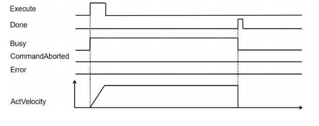
Sequence diagram
Start origin homing, and then driver normally executes origin homing, sequence diagram is as follows:
MC_HALT
MC_HALT
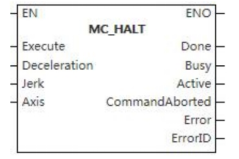
This function block is often used to stop the motion of the controlled axis under normal operating conditions.
Device used (only a single device can be used, and device splicing and offset are not supported)
| Instruction | Parameter | Devices | Index modification | Pulse expansion | |||||||||||||||||||||||||
|---|---|---|---|---|---|---|---|---|---|---|---|---|---|---|---|---|---|---|---|---|---|---|---|---|---|---|---|---|---|
| X | Y | M | S | SM | T(bit) | C(bit) | LC(bit) | HSC(bit) | D.b | KnX | KnY | KnM | KnS | T | C | D | R | SD | LC | HSC | K | H | E | [D] | XXP | ||||
| MC_HALT | Execute | ● | ● | ● | ● | ● | |||||||||||||||||||||||
| Deceleration | |||||||||||||||||||||||||||||
| Jerk | |||||||||||||||||||||||||||||
| Axis | |||||||||||||||||||||||||||||
| Done | ● | ● | ● | ● | |||||||||||||||||||||||||
| Busy | ● | ● | ● | ● | |||||||||||||||||||||||||
| Active | ● | ● | ● | ● | |||||||||||||||||||||||||
| InstructionAborted | ● | ● | ● | ● | |||||||||||||||||||||||||
| Error | ● | ● | ● | ● | |||||||||||||||||||||||||
| ErrorID | |||||||||||||||||||||||||||||
Precautions for use of devices
- LC and HSC are signed 32-bit data types;
- T, C, D, R and SD are signed 16-bit data types;
Variable Type Used
| Instruction | Parameter | Variable type | Can be empty or not | Range | Description |
| MC_HALT | Execute | BOOL | No | TRUE/FALSE | Enable |
| Deceleration | LREAL | No | 0 to 9999999.00 | Deceleration | |
| Jerk | LREAL | No | 0 to 9999999.00 | Jerk | |
| Axis | WORD | No | 0 to 65535 | Axis number | |
| Done | BOOL | No | TRUE/FALSE | Data valid or not | |
| Busy | BOOL | No | TRUE/FALSE | Busy sign | |
| Active | BOOL | No | TRUE/FALSE | Valid sign | |
| InstructionAborted | BOOL | No | TRUE/FALSE | Aborted sign | |
| Error | BOOL | No | TRUE/FALSE | Whether there is an error or not | |
| ErrorID | DWORD | No | - | Error code |
Function
- If the controlled axis is in a continuous motion state, the rising edge of the Execute signal input by the MC_Halt function block triggers the activation of the function block, so that the state of the controlled axis changes to the intermittent motion state. Similarly, if the controlled axis is in an intermittent motion state or a synchronous motion state, the activation of the MC_HALT function block will keep the controlled axis in an intermittent motion state. This function block is often used to stop the motion of the controlled axis under normal operating conditions.
Precautions
- This function block is not available when the axis does not exist.
Error code
| Error code | Content |
|---|---|
| 4084H | Data beyond the specifiable range was entered. |
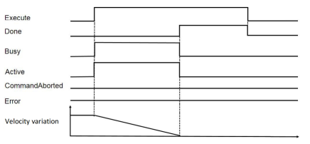
Sequence diagram
- After the call is located, trigger MC_HALT instruction, sequence diagram is as follows:
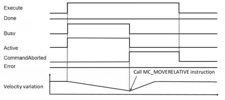
- After triggering MC_HALT instruction, call the location instruction again to interrupt the execution of MC_HALT, sequence diagram is as follows:
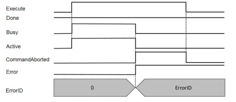
- When executing MC_HALT, showdown failure happens, sequence diagram is as follows:
MC_MOVEABSOLUTE
MC_MOVEABSOLUTE
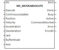
The function block makes the controlled axis reach the set absolute position with the input parameters.
Device used (only a single device can be used, and device splicing and offset are not supported)
| Instruction | Parameter | Devices | Index modification | Pulse expansion | |||||||||||||||||||||||
|---|---|---|---|---|---|---|---|---|---|---|---|---|---|---|---|---|---|---|---|---|---|---|---|---|---|---|---|
| X | Y | M | S | SM | T(bit) | C(bit) | LC(bit) | HSC(bit) | D.b | KnX | KnY | KnM | KnS | T | C | D | R | SD | LC | HSC | K | H | E | [D] | XXP | ||
| MC_MOVEABSOLUTE | Execute | ● | ● | ● | ● | ● | |||||||||||||||||||||
| ContinuousUpdate | ● | ● | ● | ● | ● | ||||||||||||||||||||||
| Position | |||||||||||||||||||||||||||
| Velocity | |||||||||||||||||||||||||||
| Acceleration | |||||||||||||||||||||||||||
| Deceleration | |||||||||||||||||||||||||||
| Jerk | |||||||||||||||||||||||||||
| BufferMode | |||||||||||||||||||||||||||
| Axis | |||||||||||||||||||||||||||
| Done | ● | ● | ● | ● | |||||||||||||||||||||||
| Busy | ● | ● | ● | ● | |||||||||||||||||||||||
| Active | ● | ● | ● | ● | |||||||||||||||||||||||
| InstructionAborted | ● | ● | ● | ● | |||||||||||||||||||||||
| Error | ● | ● | ● | ● | |||||||||||||||||||||||
| ErrorID | |||||||||||||||||||||||||||
Precautions for use of devices
- LC and HSC are signed 32-bit data types;
- T, C, D, R and SD are signed 16-bit data types;
Variable Type Used
| Instruction | Parameter | Variable type | Can be empty or not | Range | Description |
|---|---|---|---|---|---|
| MC_MOVEABSOLUTE | Execute | BOOL | No | TRUE/FALSE | Enable |
| ContinuousUpdate | BOOL | No | TRUE/FALSE | Updated during operation | |
| Position | LREAL | No | -9999999.00~9999999.00 | Absolute position | |
| Velocity | LREAL | No | 0 to 9999999.00 | Velocity | |
| Acceleration | LREAL | No | 0 to 9999999.00 | Acceleration | |
| Deceleration | LREAL | No | 0 to 9999999.00 | Deceleration | |
| Jerk | LREAL | No | 0 to 9999999.00 | Jerk | |
| BufferMode | WORD | No | 0 to 5 | Mode selection | |
| Axis | WORD | No | 0 to 65535 | Axis number | |
| Done | BOOL | No | TRUE/FALSE | Completion sign | |
| Busy | BOOL | No | TRUE/FALSE | Busy sign | |
| Active | BOOL | No | TRUE/FALSE | Valid sign | |
| InstructionAborted | BOOL | No | TRUE/FALSE | Abortion sign | |
| Error | BOOL | No | TRUE/FALSE | Whether there is an error or not | |
| ErrorID | DWORD | No | - | Error code |
Function
- The function block enables the controlled axis reach the set absolute position with input parameters (velocity, acceleration, deceleration, jerk and specified motion direction).
Precautions
- This function block is not available when the axis does not exist.
Error code
| Error code | Content |
|---|---|
| 4084H | Data beyond the specifiable range was entered. |
Sequence diagram
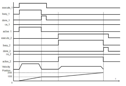
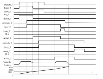
- Normal working condition sequence diagram (buffermode_1=0, buffermode_2=0):
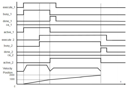
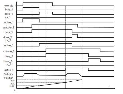
- mcAboring sequence diagram (buffermode_1=0, buffermode_2=0):
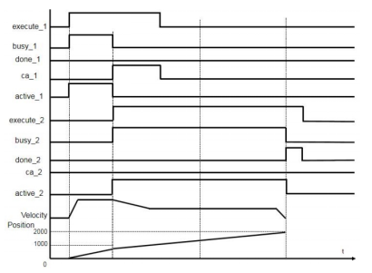
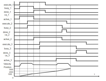
- mcBuffered sequence diagram (buffermode_1=0, buffermode_2=1):
- mcBlendingLow sequence diagram (buffermode_1=0, buffermdoe_2=2, buffermode_3=2):
- mcBlendingPrevious sequence diagram (buffermode_1=0, buffermode_2=3, buffermode_3=3)
- mcBlendingNext sequence diagram (buffermode_1=0, buffermode_2=4,buffermode_3=4):
- mcBlendingHigh sequence diagram (buffermode_1=0, buffermode_2=5, buffermode_3=5):
MC_MOVERELATIVE
MC_MOVERELATIVE
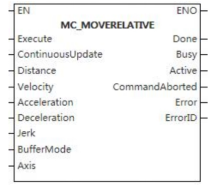
The function block makes the controlled axis reach the set absolute position with the input parameters.
Device used (only a single device can be used, and device splicing and offset are not supported)
| Instruction | Parameter | Devices | Index modification | Pulse expansion | |||||||||||||||||||||||
|---|---|---|---|---|---|---|---|---|---|---|---|---|---|---|---|---|---|---|---|---|---|---|---|---|---|---|---|
| X | Y | M | S | SM | T(bit) | C(bit) | LC(bit) | HSC(bit) | D.b | KnX | KnY | KnM | KnS | T | C | D | R | SD | LC | HSC | K | H | E | [D] | XXP | ||
| MC_MOVERELATIVE | Execute | ● | ● | ● | ● | ● | |||||||||||||||||||||
| ContinuousUpdate | ● | ● | ● | ● | ● | ||||||||||||||||||||||
| Distance | |||||||||||||||||||||||||||
| Velocity | |||||||||||||||||||||||||||
| Acceleration | |||||||||||||||||||||||||||
| Deceleration | |||||||||||||||||||||||||||
| Jerk | |||||||||||||||||||||||||||
| BufferMode | |||||||||||||||||||||||||||
| Axis | |||||||||||||||||||||||||||
| Done | ● | ● | ● | ● | |||||||||||||||||||||||
| Busy | ● | ● | ● | ● | |||||||||||||||||||||||
| Active | ● | ● | ● | ● | |||||||||||||||||||||||
| InstructionAborted | ● | ● | ● | ● | |||||||||||||||||||||||
| Error | ● | ● | ● | ● | |||||||||||||||||||||||
| ErrorID | |||||||||||||||||||||||||||
Precautions for use of devices
- LC and HSC are signed 32-bit data types;
- T, C, D, R and SD are signed 16-bit data types.
Variable Type Used
| Instruction | Parameter | Variable type | Can be empty or not | Range | Description |
|---|---|---|---|---|---|
| MC_MOVERELATIVE | Execute | BOOL | No | TRUE/FALSE | Enable |
| ContinuousUpdate | BOOL | No | TRUE/FALSE | Updated during operation | |
| Distance | LREAL | No | -9999999.00~9999999.00 | Relative position | |
| Velocity | LREAL | No | 0 to 9999999.00 | Velocity | |
| Acceleration | LREAL | No | 0 to 9999999.00 | Acceleration | |
| Deceleration | LREAL | No | 0 to 9999999.00 | Deceleration | |
| Jerk | LREAL | No | 0 to 9999999.00 | Jerk | |
| BufferMode | WORD | No | 0 to 5 | Mode selection | |
| Axis | WORD | No | 0 to 65535 | Axis number | |
| Done | BOOL | No | TRUE/FALSE | Completion sign | |
| Busy | BOOL | No | TRUE/FALSE | Busy sign | |
| Active | BOOL | No | TRUE/FALSE | Valid sign | |
| InstructionAborted | BOOL | No | TRUE/FALSE | Abortion sign | |
| Error | BOOL | No | TRUE/FALSE | Whether there is an error or not | |
| ErrorID | DWORD | No | - | Error code |
Function
- The function block takes the current position as the starting point of motion and controls the controlled axis to reach the set relative position (Distance) with the set parameters (velocity, acceleration, deceleration and jerk), It refers to the motion control that takes starting point of the motion + Distance as the end point.
Precautions
- This function block is not available when the axis does not exist.
Error code
| Error code | Content |
|---|---|
| 4084H | Data beyond the specifiable range was entered. |
Sequence diagram
- Normal working condition sequence diagram (buffermode_1=0, buffermode_2=0):
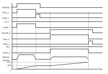
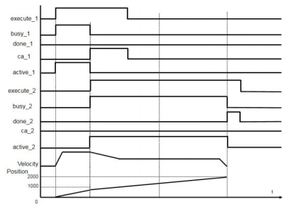
- mcAboring sequence diagram (buffermode_1=0, buffermode_2=0):
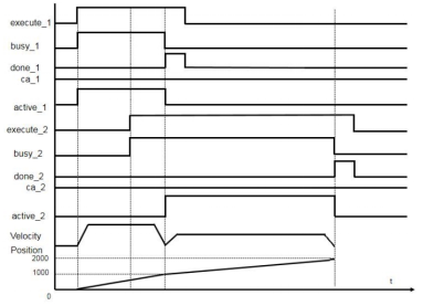
- mcBuffered sequence diagram (buffermode_1=0, buffermode_2=1):
- mcBlendingLow sequence diagram (buffermode_1=0, buffermdoe_2=2, buffermode_3=2)
- mcBlendingPrevious sequence diagram (buffermode_1=0, buffermode_2=3, buffermode_3=3)
- mcBlendingNext sequence diagram (buffermode_1=0, buffermode_2=4,buffermode_3=4):
- McBlendingHigh sequence diagram (buffermode_1=0, buffermode_2=5, buffermode_3=5):
MC_MOVEADDITIVE
MC_MOVEADDITIVE
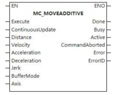
This function block is a motion increment function block.
Device used (only a single device can be used, and device splicing and offset are not supported)
| Instruction | Parameter | Devices | Index modification | Pulse expansion | |||||||||||||||||||||||
|---|---|---|---|---|---|---|---|---|---|---|---|---|---|---|---|---|---|---|---|---|---|---|---|---|---|---|---|
| X | Y | M | S | SM | T(bit) | C(bit) | LC(bit) | HSC(bit) | D.b | KnX | KnY | KnM | KnS | T | C | D | R | SD | LC | HSC | K | H | E | [D] | XXP | ||
| MC_MOVEADDITIVE | Execute | ● | ● | ● | ● | ● | |||||||||||||||||||||
| ContinuousUpdate | ● | ● | ● | ● | ● | ||||||||||||||||||||||
| Distance | |||||||||||||||||||||||||||
| Velocity | |||||||||||||||||||||||||||
| Acceleration | |||||||||||||||||||||||||||
| Deceleration | |||||||||||||||||||||||||||
| Jerk | |||||||||||||||||||||||||||
| BufferMode | |||||||||||||||||||||||||||
| Axis | |||||||||||||||||||||||||||
| Done | ● | ● | ● | ● | |||||||||||||||||||||||
| Busy | ● | ● | ● | ● | |||||||||||||||||||||||
| Active | ● | ● | ● | ● | |||||||||||||||||||||||
| InstructionAborted | ● | ● | ● | ● | |||||||||||||||||||||||
| Error | ● | ● | ● | ● | |||||||||||||||||||||||
| ErrorID | |||||||||||||||||||||||||||
Precautions for use of devices
- LC and HSC are signed 32-bit data types;
- T, C, D, R and SD are signed 16-bit data types.
Variable Type Used
| Instruction | Parameter | Variable type | Can be empty or not | Range | Description |
|---|---|---|---|---|---|
| MC_MOVEADDITIVE | Execute | BOOL | No | TRUE/FALSE | Enable |
| ContinuousUpdate | BOOL | No | TRUE/FALSE | Updated during operation | |
| Distance | LREAL | No | -9999999.00~9999999.00 | Relative position | |
| Velocity | LREAL | No | 0 to 9999999.00 | Velocity | |
| Acceleration | LREAL | No | 0 to 9999999.00 | Acceleration | |
| Deceleration | LREAL | No | 0 to 9999999.00 | Deceleration | |
| Jerk | LREAL | No | 0 to 9999999.00 | Jerk | |
| BufferMode | WORD | No | 0 to 5 | Mode selection | |
| Axis | WORD | No | 0 to 65535 | Axis number | |
| Done | BOOL | No | TRUE/FALSE | Completion sign | |
| Busy | BOOL | No | TRUE/FALSE | Busy sign | |
| Active | BOOL | No | TRUE/FALSE | Valid sign | |
| InstructionAborted | BOOL | No | TRUE/FALSE | Abortion sign | |
| Error | BOOL | No | TRUE/FALSE | Whether there is an error or not | |
| ErrorID | DWORD | No | - | Error code |
Function
- It is used to add the input parameters (velocity, acceleration, deceleration and jerk) specified by this function block to reach the specified distance (Distance) on the basis of existing motion, i.e., adding distance.
Precautions
- This function block is not available when the axis does not exist.
Error code
| Error code | Content |
|---|---|
| 4084H | Data beyond the specifiable range was entered. |
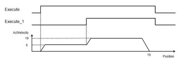
Sequence diagram
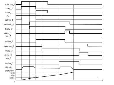
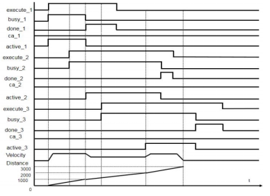
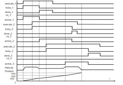
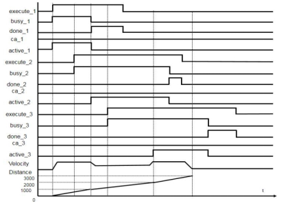
When using MC_MOVEABSOLUTE with MC_MOVEADDITIVE together, and when the tagret position of MC_MOVEABSOLUTE is 10 and velocity is 5, the stacked position of MC_MOVEADDITIVE is 15 and velocity is 10, the relationship between position and velocity of Axis_0 is as follows:
MC_MOVESUPERIMPOSED
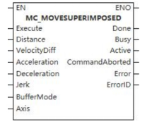
MC_MOVESUPERIMPOSED
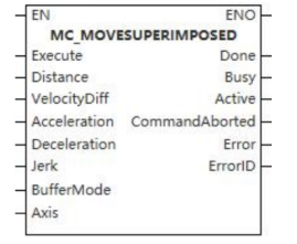
This function block is a motion superposition function block.
Device used (only a single device can be used, and device splicing and offset are not supported)
| Instruction | Parameter | Devices | Index modification | Pulse expansion | |||||||||||||||||||||||
|---|---|---|---|---|---|---|---|---|---|---|---|---|---|---|---|---|---|---|---|---|---|---|---|---|---|---|---|
| X | Y | M | S | SM | T(bit) | C(bit) | LC(bit) | HSC(bit) | D.b | KnX | KnY | KnM | KnS | T | C | D | R | SD | LC | HSC | K | H | E | [D] | XXP | ||
| MC_MOVESUPERIMPOSED | Execute | ● | ● | ● | ● | ● | |||||||||||||||||||||
| ContinuousUpdate | ● | ● | ● | ● | ● | ||||||||||||||||||||||
| Distance | |||||||||||||||||||||||||||
| VelocityDiff | |||||||||||||||||||||||||||
| Acceleration | |||||||||||||||||||||||||||
| Deceleration | |||||||||||||||||||||||||||
| Jerk | |||||||||||||||||||||||||||
| BufferMode | |||||||||||||||||||||||||||
| Axis | |||||||||||||||||||||||||||
| Done | ● | ● | ● | ● | |||||||||||||||||||||||
| Busy | ● | ● | ● | ● | |||||||||||||||||||||||
| Active | ● | ● | ● | ● | |||||||||||||||||||||||
| InstructionAborted | ● | ● | ● | ● | |||||||||||||||||||||||
| Error | ● | ● | ● | ● | |||||||||||||||||||||||
| ErrorID | |||||||||||||||||||||||||||
Precautions for use of devices
- LC and HSC are signed 32-bit data types;
- T, C, D, R and SD are signed 16-bit data types;
Variable Type Used
| Instruction | Parameter | Variable type | Can be empty or not | Range | Description |
|---|---|---|---|---|---|
| MC_MOVESUPERIMPOSED | Execute | BOOL | No | TRUE/FALSE | Enable |
| ContinuousUpdate | BOOL | No | TRUE/FALSE | Updated during operation | |
| Distance | LREAL | No | -9999999.00~9999999.00 | Relative position | |
| VelocityDiff | LREAL | No | 0 to 9999999.00 | Velocity | |
| Acceleration | LREAL | No | 0 to 9999999.00 | Acceleration | |
| Deceleration | LREAL | No | 0 to 9999999.00 | Deceleration | |
| Jerk | LREAL | No | 0 to 9999999.00 | Jerk | |
| BufferMode | WORD | No | 0 to 5 | Mode selection | |
| Axis | WORD | No | 0 to 65535 | Axis number | |
| Done | BOOL | No | TRUE/FALSE | Completion sign | |
| Busy | BOOL | No | TRUE/FALSE | Busy sign | |
| Active | BOOL | No | TRUE/FALSE | Valid sign | |
| InstructionAborted | BOOL | No | TRUE/FALSE | Abortion sign | |
| Error | BOOL | No | TRUE/FALSE | Whether there is an error or not | |
| ErrorID | DWORD | No | - | Error code |
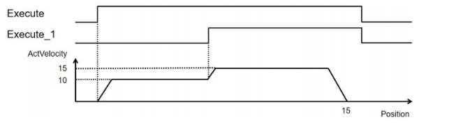
Function
- This function block is used to superpose the motion, which means that on the basis of current motion speed, the velocity difference is added so that the input acceleration, deceleration and jerk are also increased based on the original motion values, i.e., increasing the velocity and making the controlled axis move to the specified (relative) distance (Distance).
Precautions
- This function block is not available when the axis does not exist;
- When it executes, the previous function block should be executed first.
Error code
| Error code | Content |
|---|---|
| 4084H | Data beyond the specifiable range was entered. |
Sequence diagram
Management Function Blocks for Multi-axis Motion Control
MC_CAMTABLESELECT
MC_CAMTABLESELECT
This function block is used to bind the cam table.
Device used (only a single device can be used, and device splicing and offset are not supported)
| Instruction | Parameter | Devices | Index modification | Pulse expansion | |||||||||||||||||||||||
|---|---|---|---|---|---|---|---|---|---|---|---|---|---|---|---|---|---|---|---|---|---|---|---|---|---|---|---|
| X | Y | M | S | SM | T(bit) | C(bit) | LC(bit) | HSC(bit) | D.b | KnX | KnY | KnM | KnS | T | C | D | R | SD | LC | HSC | K | H | E | [D] | XXP | ||
| MC_CAMTABLESELECT | Execute | ● | ● | ● | ● | ● | |||||||||||||||||||||
| Periodic | ● | ● | ● | ● | ● | ||||||||||||||||||||||
| MasterAbsolute | ● | ● | ● | ● | ● | ||||||||||||||||||||||
| SlaveAbsolute | ● | ● | ● | ● | ● | ||||||||||||||||||||||
| Master | |||||||||||||||||||||||||||
| Slave | |||||||||||||||||||||||||||
| CamTable | ● | ||||||||||||||||||||||||||
| Done | ● | ● | ● | ● | |||||||||||||||||||||||
| Busy | ● | ● | ● | ● | |||||||||||||||||||||||
| Error | ● | ● | ● | ● | |||||||||||||||||||||||
| ErrorID | |||||||||||||||||||||||||||
| CamTableID | |||||||||||||||||||||||||||
Precautions for use of devices
- LC and HSC are signed 32-bit data types;
- T, C, D, R and SD are signed 16-bit data types;
Variable Type Used
| Instruction | Parameter | Variable type | Can be empty or not | Range | Description |
|---|---|---|---|---|---|
| MC_CAMTABLESELECT | Execute | BOOL | No | TRUE/FALSE | Enable |
| Periodic | BOOL | No | TRUE/FALSE | Cyclic mode setting | |
| MasterAbsolute | BOOL | No | TRUE/FALSE | Master axis position mode setting | |
| SlaveAbsolute | BOOL | No | TRUE/FALSE | Slave axis position mode setting | |
| Master | WORD | No | - | Master axis | |
| Slave | WORD | No | - | Slave axis | |
| CamTable | Cam table (INT type variable) | No | - | Cam table | |
| Done | BOOL | No | TRUE/FALSE | Completion sign | |
| Busy | BOOL | No | TRUE/FALSE | Busy sign | |
| Error | BOOL | No | TRUE/FALSE | Whether there is an error or not | |
| ErrorID | DWORD | No | - | Error code | |
| CamTableID | WORD | No | - | Cam table identification number |
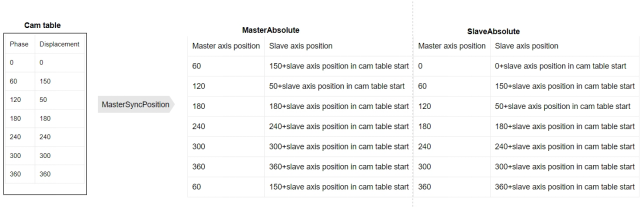
Function
- When MasterAbsolute is true, it means the master axis is under the absolute mode; when MasterAbsolute is false, it means the master axis is under the relative mode;
- When SlaveAbsolute is true, it means the slave axis is under the absolute mode; when SlaveAbsolute is false, it means the slave axis is under the relative mode;
- This function block is used to bind the cam table, that is, to bind the input master axis, slave axis and cam table. When calling MC_CAMIN function block, only the cam table bound by this function block can be used.
Precautions
- This function block is not available when the axis does not exist.
Error code
| Error code | Content |
|---|---|
| 4084H | Data beyond the specifiable range was entered. |
Sequence diagram
MC_GENERATECAMTABLE
MC_GENERATECAMTABLE
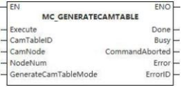
This function block is used to update the cam table.
Device used (Only a single device can be used, and device splicing and offset are not supported)
Instruction |
Parameter | Devices | Index modification | Pulse expansion | |||||||||||||||||||||||
|---|---|---|---|---|---|---|---|---|---|---|---|---|---|---|---|---|---|---|---|---|---|---|---|---|---|---|---|
| X | Y | M | S | SM | T(bit) | C(bit) | LC(bit) | HSC(bit) | D.b | KnX | KnY | KnM | KnS | T | C | D | R | SD | LC | HSC | K | H | E | [D] | XXP | ||
MC_GENERATECAMTABLE | Execute |  |  |  |  |  | |||||||||||||||||||||
| CamTableID | |||||||||||||||||||||||||||
| CamNode | |||||||||||||||||||||||||||
| NodeNum |  | ||||||||||||||||||||||||||
Generatecam TableMode |  | ||||||||||||||||||||||||||
| Done |  |  |  |  | |||||||||||||||||||||||
| Busy |  |  |  |  | |||||||||||||||||||||||
| InstructionAborted |
|
|
|
| |||||||||||||||||||||||
| Error |  | ||||||||||||||||||||||||||
| ErrorID | |||||||||||||||||||||||||||


Precautions for use of devices
- LC and HSC are signed 32-bit data types;
- T, C, D, R and SD are signed 16-bit data types;
Variable type used
| Instruction | Pin | Parameter | Variable type | Can it be empty | Range | Description |
|---|---|---|---|---|---|---|
MC_GENERATECAMTABLE |
Input | Execute | BOOL | No | TRUE/FALSE | Enable |
| CamTableID | INT | No | Cam tableID | |||
| CamNode | ARRAY (CAMNODET) | No | - | Array of cam nodes | ||
| NodeNum | INT | No | 2 ~361 | Number of cam nodes | ||
GeneratecamTable Mode |
INT |
No |
| Effective mode 0: Effective in the next cam cycle; Others: Reserved | ||
Output | Done | BOOL | Yes | TRUE/FALSE | Busy flag | |
| BusY | BOOL | Yes | TRUE/FALSE | Aborted flag | ||
| InstructionAborted | BOOL | Yes | TRUE/FALSE | Abortion flag | ||
| Error | BOOL | Yes | Whether there is an error or not | |||
| ErrorID | DWORD | Yes | Error Code (Please check [8.10 Error Code Cross-reference Table] ) |
Function
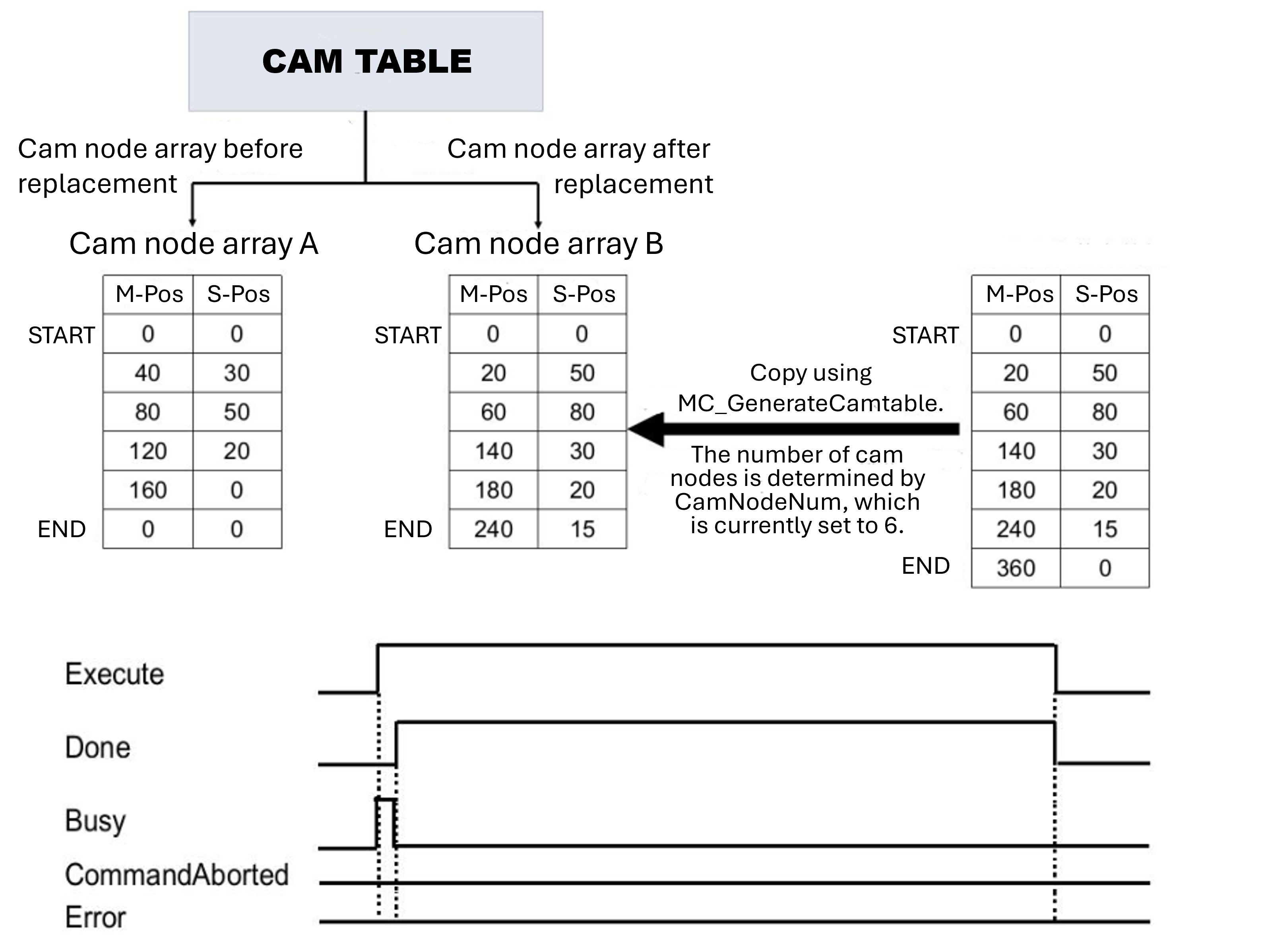
- This function block is used to update cam table. At the rising edge of startup, the cam data is calculated based on values of input variables camNode and NodeNum. The data is updated to the cam table specified by camTable, which is will be effective in the next cam cycle.
Sequence diagram
MC_SAVECAMTABLE
MC_SAVECAMTABLE
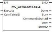
This function block is used to save the cam table.
Device used (Only a single device can be used, and device splicing and offset are not supported)
Instruction |
Parameter | Devices | Index modification | Pulse expansion | |||||||||||||||||||||||
|---|---|---|---|---|---|---|---|---|---|---|---|---|---|---|---|---|---|---|---|---|---|---|---|---|---|---|---|
| X | Y | M | S | SM | T(bit) | C(bit) | LC(bit) | HSC(bit) | D.b | KnX | KnY | KnM | KnS | T | C | D | R | SD | LC | HSC | K | H | E | [D] | XXP | ||
MC_SAVECAMTABLE | Execute |  |  |  |  |  | |||||||||||||||||||||
| CamTableID | |||||||||||||||||||||||||||
| Done |  |  |  |  | |||||||||||||||||||||||
| Busy |  |  |  |  | |||||||||||||||||||||||
| InstructionAborted |  |  |  |  | |||||||||||||||||||||||
| Error |  |  |  |  | |||||||||||||||||||||||
| ErrorID | |||||||||||||||||||||||||||
Precautions for use of devices
- LC and HSC are signed 32-bit data types;
- T, C, D, R and SD are signed 16-bit data types;
Variable type used
| Instruction | Pin | Parameter | Variable type | Can it be empty | Range | Description |
|---|---|---|---|---|---|---|
MC_SAVECAMTABLE | Input | Execute | BOOL | No | TRUE/FALSE | Enable |
| CamTableID | INT | No | - | Cam tableID | ||
| Output | Done | BOOL | Yes | TRUE/FALSE | Busy flag | |
| BusY | BOOL | Yes | TRUE/FALSE | Aborted flag | ||
| InstructionAborted | BOOL | Yes | TRUE/FALSE | Abortion flag | ||
| Error | BOOL | Yes | - | Whether there is an error or not | ||
| ErrorID | DWORD | Yes | - | Error Code (Please check [8.10 Error Code Cross-reference Table] |
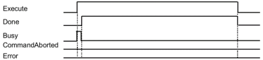
Function
- This function block is used to save the specified cam table.
Error code
| Error code | Content |
|---|---|
| 4084H | Data beyond the specifiable range was entered. |
Sequence diagram
Motion Function Block for Multi-axis Motion Control
MC_CAMIN
MC_CAMIN
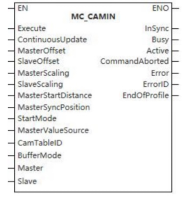
The function block enables the controlled axis to carry out cam motion.
Device used (only a single device can be used, and device splicing and offset are not supported)
| Instruction | Parameter | Devices | Index modification | Pulse expansion | |||||||||||||||||||||||
|---|---|---|---|---|---|---|---|---|---|---|---|---|---|---|---|---|---|---|---|---|---|---|---|---|---|---|---|
| X | Y | M | S | SM | T(bit) | C(bit) | LC(bit) | HSC(bit) | D.b | KnX | KnY | KnM | KnS | T | C | D | R | SD | LC | HSC | K | H | E | [D] | XXP | ||
| MC_CAMIN | Execute | ● | ● | ● | ● | ● | |||||||||||||||||||||
| ContinuousUpdate | ● | ● | ● | ● | ● | ||||||||||||||||||||||
| MasterIndex | |||||||||||||||||||||||||||
| SlaveIndex | |||||||||||||||||||||||||||
| MasterScaling | |||||||||||||||||||||||||||
| SlaveScaling | |||||||||||||||||||||||||||
| MasterStartDistance | |||||||||||||||||||||||||||
| MasterSyncPosition | |||||||||||||||||||||||||||
| StartMode | |||||||||||||||||||||||||||
| MasterValueSource | |||||||||||||||||||||||||||
| CamTableID | |||||||||||||||||||||||||||
| BufferMode | |||||||||||||||||||||||||||
| Master | |||||||||||||||||||||||||||
| Slave | |||||||||||||||||||||||||||
| InSync | ● | ● | ● | ● | |||||||||||||||||||||||
| Busy | ● | ● | ● | ● | |||||||||||||||||||||||
| Active | ● | ● | ● | ● | |||||||||||||||||||||||
| InstructionAborted | ● | ● | ● | ● | |||||||||||||||||||||||
| Error | ● | ● | ● | ● | |||||||||||||||||||||||
| ErrorID | |||||||||||||||||||||||||||
| EndOfProfile | |||||||||||||||||||||||||||
Precautions for use of devices
- LC and HSC are signed 32-bit data types;
- T, C, D, R and SD are signed 16-bit data types;
Variable Type Used
| Instruction | Parameter | Variable type | Can be empty or not | Range | Description |
|---|---|---|---|---|---|
| MC_CAMIN | Execute | BOOL | No | TRUE/FALSE | Enable |
| ContinuousUpdate | BOOL | No | TRUE/FALSE | Updated during operation (reserve) | |
| MasterIndex | LREAL | No | -9999999.00~9999999.00 | Master axis offset | |
| SlaveIndex | LREAL | No | -9999999.00~9999999.00 | Slave axis bias | |
| MasterScaling | LREAL | No | -9999999.00~9999999.00 | Master axis scaling factor | |
| SlaveScaling | LREAL | No | -9999999.00~9999999.00 | Slave axis scaling factor | |
| MasterStartDistance | LREAL | No | -9999999.00~9999999.00 (not 0) | Master axis starting distance | |
| MasterSyncPosition | LREAL | No | -9999999.00~9999999.00 | Master axis synchronization position | |
| StartMode | WORD | No | 0 to 2 | Start mode (0-Absolute, 1-Relative, 2-Catchup) | |
| MasterValueSource | WORD | No | 0 to 2 | Master axis synchronization source (Instruction value, set value and actual value) | |
| CamTableID | WORD | No | 0 to 9999999.00 | Electronic CAM table identification | |
| BufferMode | WORD | No | 0 | Mode selection | |
| Master | WORD | No | - | Master axis | |
| Slave | WORD | No | - | Slave axis | |
| InSync | BOOL | No | TRUE/FALSE | Completion sign | |
| Busy | BOOL | No | TRUE/FALSE | Busy sign | |
| Active | BOOL | No | TRUE/FALSE | Valid sign | |
| InstructionAborted | BOOL | No | TRUE/FALSE | Abortion sign | |
| Error | BOOL | No | TRUE/FALSE | Whether there is an error or not | |
| ErrorID | DWORD | No | - | Error code | |
| EndOfProfile | WORD | No | - | Electronic CAM end signal |
Function
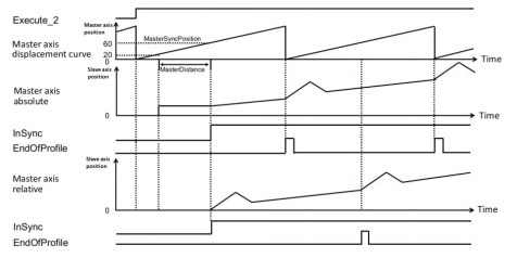
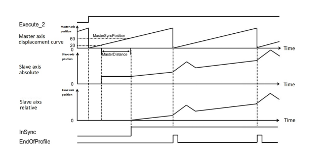
- This function starts with the input parameter MasterSyncPosition. Before reaching the MasterSyncPosition, the catchup or transition motion is carried out according to the set parameters (absolute relative of the master axis, absolute relative of the slave axis, starting mode). After reaching the MasterSyncPosition position, the positional relationship between the master axis and the slave axis is obtained according to the camTableID, and the relationship is corrected under the set offset and scaling factors of the master axis and the slave axis, and the cam motion is carried out.
- MasterSyncPosition
MasterSyncPosition is the absolute position when the axis mode is absolute;
MasterSyncPosition is the relative position when the axis mode is relative;
- ImSync status bit is turned ON when the master axis reaches MasterSyncPosition position and the slave axis reaches the slave axis position corresponding to the cam table of the master axis. Generally speaking, when the slave axis is in relative mode, the MC_CAMIN instruction is executed, and this status bit will be turned ON immediately; when the slave axis is in absolute or tracing mode, the status bit will be turned ON immediately after the slave axis jumps or traces to the position corresponding to the master axis cam table.
- The EndOfProfle status bit is turned ON after the slave axis has followed the master axis through the entire cam table; The StartMode parameter, together with the MasterAbsolute/SlaverAbsolute parameters in the MC_CAMTABLESELECT instruction, determines the motion mode of the master/slave axis.
- The master mode is only determined by MasterAbsolute and is not affected by the value in StartMode. The slave axis mode is expressed as follows:
| StartMode | SlaveAbsolute | Slave axis mode |
|---|---|---|
| Absolute | Relative | Relative |
| Absolute | Absolute | Absolute |
| Relative | Relative | Relative |
| Relative | Absolute | Relative |
| Catch up | Relative | Relative catch up |
| Catch up | Absolute | Relative catch up |
| Master axis mode | Slave axis mode | Result |
|---|---|---|
| Relative | Relative | When CAMIN is executed, slave axis position jumps to the set offset position; When master axis is executing, slave axis performs relative motion according to the start position of cam table. |
| Absolute | When CAMIN is executed, slave axis position jumps to the cam table start position (i.e., 0); When the master axis is executing, slave axis moves according to the corresponding point position of the cam table. | |
| Relative | When CAMIN is executed, slave axis position catches up to the set offset position; When the master axis is executing, the slave axis performs relative motion according to the corresponding points of the cam table. | |
| Absolute catch up | When CAMIN is executed, slave axis position catches up to the cam table starting position (i.e., 0); When the master axis is executing, the slave axis moves according to the corresponding point position of the cam table. | |
| Absolute | Relative | When CAMIN is executed, slave axis position jumps to the set offset position; When the master axis is executing, the slave axis performs relative motion according to the points corresponding to the cam table. |
| Absolute | When CAMIN is executed, slave axis position jumps to the current slave axis position corresponding to the master axis in the cam table (For example, if the current position of the master axis is 100 and the slave axis point corresponding to the master axis point 100 in the cam table is 200, the slave axis jumps after CAMIN is executed;) After the master axis is executing, slave axis performs relative motion according to the corresponding points in the cam table. | |
| Relative catch up | When CAMIN is executed, slave axis position catches up to the set offset position; When the master axis is executing, slave axis performs relative motion according to the corresponding points of the cam table. | |
| Absolute catch up | When CAMIN is executed, slave axis position catches up to the current slave axis position corresponding to the master axis in the cam table (For example, if the current position of the master axis is 100 and the slave axis point corresponding to the master axis point 100 in the cam table is 200, the slave axis jumps after CAMIN is executed;) After the master axis is running, the slave axis performs relative motion to the corresponding points in the cam table. |
- When axis is in absolute mode, if the current position of the axis is not within the range of the axis in the cam table, it will be processed by self-acting periodization.
Example: the current axis position is 110, and the axis position in the cam table is 0~100, then the default axis position after CAMIN execution is 10 (the actual axis position does not change);
- The master-slave axis multiplier and master-slave axis offset parameters take effect when CAMIN is executed and do not support modification in the process; unsuitable parameters will cause the slave axis position to jump.
- The master-slave position relationship (where CAM () indicates the corresponding slave position of the master axis on the cam table):
Master Position = Master Position * Master Multiplier + Master Offset
Slave position = Slave multiplier * CAM (spindle position) + Slave offset
- The master-slave multiplier cannot be 0.
Precautions
- This function block is not available when the axis does not exist;
- The motion mode of the slave axis shall be determined according to start mode and SlaveAbsolute of CamtableSelect. See “Chapter 8.6” [Description of Several Modes in E-CAM] for details. MasterValueSource is now an actual value regardless of which mode you choose.
Error code
| Error code | Content |
|---|---|
| 4084H | Data beyond the specifiable range was entered. |
Sequence diagram
▪ MC_CAMIN needs to be used in conjunction with MC_CAMTABLESELECT and a single-axis motion (e.g., MC_MOVEABSOLUTE), the sequence diagram is as follows.
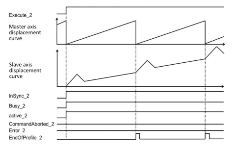
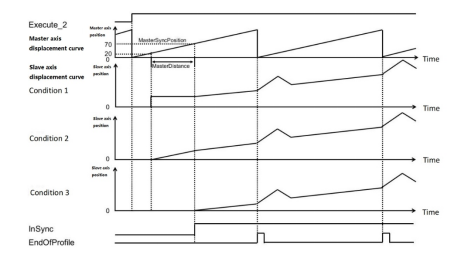
(1) Slave motion varies depending on StartMode.
Assume that the start conditions for cam motion are as follows:
▪ In condition 1, the master axis jumps at the position of 20 (70~50), and the jumping position is the cam table position corresponding to masterSyncPosition, and the output variable InSync (in synchronization) changes to TRUE when it passes the position of 70, and the slave axis starts camming.
▪ In condition 2, the master axis will catch up at 20 (70~50), and the catch-up position is the cam table position corresponding to masterSyncPosition, and the output variable InSync (in synchronization) becomes TRUE when it passes the position of 70, and the slave axis starts camming.
▪ In condition 3, the output variable InSync (in synchronization) becomes TRUE when the master axis passes the position of 70, and the slave axis starts camming.
| Input variable | Condition 1 | Condition 2 | Condition 3 |
|---|---|---|---|
| MasterAbsolute | True (Absolute) | True (Absolute) | True (Absolute) |
| SlaveAbsolute | True (Absolute) | True (Absolute) | FALSE (Relative) |
| StartMode | MC_START_MODE_ABSOLUTE | MC_START_MODE_RAMPIN | MC_START_MODE_RELATIVE |
| MasterSyncPosition | 70 | 70 | 70 |
| MasterDistace | 50 | 50 | 50 |
| MasterOffset | 0 | 0 | 0 |
| SlaveOffset | 0 | 0 | 0 |
| MasterScaling | 1 | 1 | 1 |
| SlaveScaling | 1 | 1 | 1 |
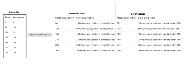
(2) Slave motion varies depending on MasterAbsolute.
(3)Slave motion varies depending on SlaveAbsolute.
MC_CAMOUT
MC_CAMOUT
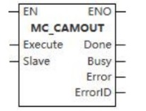
The function block enables the controlled axis to carry out uniform motion at current velocity.
Device used (only a single device can be used, and device splicing and offset are not supported)
| Instruction | Parameter | Devices | Index modification | Pulse expansion | |||||||||||||||||||||||
|---|---|---|---|---|---|---|---|---|---|---|---|---|---|---|---|---|---|---|---|---|---|---|---|---|---|---|---|
| X | Y | M | S | SM | T(bit) | C(bit) | LC(bit) | HSC(bit) | D.b | KnX | KnY | KnM | KnS | T | C | D | R | SD | LC | HSC | K | H | E | [D] | XXP | ||
| MC_CAMOUT | Execute | ● | ● | ● | ● | ● | |||||||||||||||||||||
| Slave | |||||||||||||||||||||||||||
| Done | ● | ● | ● | ● | |||||||||||||||||||||||
| Busy | ● | ● | ● | ● | |||||||||||||||||||||||
| Error | ● | ● | ● | ● | |||||||||||||||||||||||
| ErrorID | |||||||||||||||||||||||||||
Precautions for use of devices
- LC and HSC are signed 32-bit data types;
- T, C, D, R and SD are signed 16-bit data types;
Variable Type Used
| Instruction | Parameter | Variable type | Can be empty or not | Range | Description |
|---|---|---|---|---|---|
| MC_CAMOUT | Execute | BOOL | No | TRUE/FALSE | Enable |
| Slave | WORD | No | 0 to 65535 | Slave axis | |
| Done | BOOL | No | TRUE/FALSE | Completion sign | |
| Busy | BOOL | No | TRUE/FALSE | Busy sign | |
| Error | BOOL | No | TRUE/FALSE | Whether there is an error or not | |
| ErrorID | DWORD | No | - | Error code |
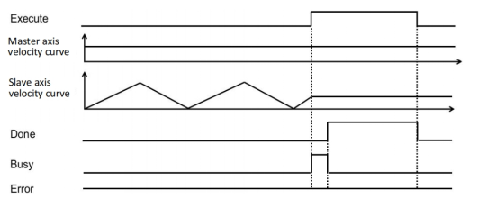
Function
- The function is used to separate the slave axis from the position relation specified for the electronic cam. Execute the MC_CamOut function block to transform the slave shaft from the synchronous state to the continuous motion state. The current velocity of the slave axis is maintained.
Precautions
- This function block is not available when the axis does not exist.
Sequence diagram
MC_GEARIN
MC_GEARIN
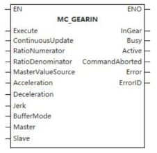
The function block enables the controlled axis to carry out gear motion.
Device used (only a single device can be used, and device splicing and offset are not supported)
| Instruction | Parameter | Devices | Index modification | Pulse expansion | |||||||||||||||||||||||
|---|---|---|---|---|---|---|---|---|---|---|---|---|---|---|---|---|---|---|---|---|---|---|---|---|---|---|---|
| X | Y | M | S | SM | T(bit) | C(bit) | LC(bit) | HSC(bit) | D.b | KnX | KnY | KnM | KnS | T | C | D | R | SD | LC | HSC | K | H | E | [D] | XXP | ||
| MC_GEARIN | Execute | ● | ● | ● | ● | ● | |||||||||||||||||||||
| ContinuousUpdate | ● | ● | ● | ● | ● | ||||||||||||||||||||||
| RatioNumerator | |||||||||||||||||||||||||||
| RatioDenominator | |||||||||||||||||||||||||||
| MasterValueSource | |||||||||||||||||||||||||||
| Acceleration | |||||||||||||||||||||||||||
| Deceleration | |||||||||||||||||||||||||||
| Jerk | |||||||||||||||||||||||||||
| BufferMode | |||||||||||||||||||||||||||
| Master | |||||||||||||||||||||||||||
| Slave | |||||||||||||||||||||||||||
| InGear | ● | ● | ● | ● | |||||||||||||||||||||||
| Busy | ● | ● | ● | ● | |||||||||||||||||||||||
| Active | ● | ● | ● | ● | |||||||||||||||||||||||
| InstructionAborted | ● | ● | ● | ● | |||||||||||||||||||||||
| Error | ● | ● | ● | ● | |||||||||||||||||||||||
| ErrorID | |||||||||||||||||||||||||||
Precautions for use of devices
- LC and HSC are signed 32-bit data types;
- T, C, D, R and SD are signed 16-bit data types;
Variable Type Used
| Instruction | Parameter | Variable type | Can be empty or not | Range | Description |
|---|---|---|---|---|---|
| MC_GEARIN | Execute | BOOL | No | TRUE/FALSE | Enable |
| ContinuousUpdate | BOOL | No | TRUE/FALSE | Updated during operation (reserve) | |
| RatioNumerator | UNIT | No | [-32768,0)U(0,32767] | Gear velocity ratio (numerator) | |
| RatioDenominator | UDINT | No | (0,65535] | Gear velocity ratio (denominator) | |
| MasterValueSource | WORD | No | 0 to 2 | Master axis synchronization source (Instruction value, set value and actual value) | |
| Acceleration | LREAL | No | 0 to 9999999.99999 | Acceleration | |
| Deceleration | LREAL | No | 0 to 9999999.99999 | Deceleration | |
| Jerk | LREAL | No | 0 to 9999999.99999 | Jerk | |
| BufferMode | WORD | No | 0 to 5 | Selection | |
| Master | WORD | No | 0 to 65536 | Master axis | |
| Slave | WORD | No | 0 to 65536 | Slave axis | |
| InGear | BOOL | No | TRUE/FALSE | Completion sign | |
| Busy | BOOL | No | TRUE/FALSE | Busy sign | |
| Active | BOOL | No | TRUE/FALSE | Valid sign | |
| InstructionAborted | BOOL | No | TRUE/FALSE | Abortion sign | |
| Error | BOOL | No | TRUE/FALSE | Whether there is an error or not | |
| ErrorID | DWORD | No | - | Error code |
Function
- The function block is used for establishing the synchronization of the velocity ratio between the master axis and the slave axis. Firstly, the slave axis takes the velocity of master axis multiplied by the velocity ratio as the target velocity and moves at the set acceleration and jerk and executes gear motion according to the velocity of master axis when reaching the target motion.
Precautions
- This function block is not available when the axis does not exist.
Error code
| Error code | Content |
|---|---|
| 4084H | Data beyond the specifiable range was entered. |
Sequence diagram
- After starting the motion, the slave axis performs acceleration and deceleration with the velocity obtained by multiplying the spindle speed by the gear ratio as the target speed;
- Before reaching target position is called the Catching phase and after reaching it is called the InGear phase;
- The gear ratio is positive and the slave axis moves in the same direction as the master axis.
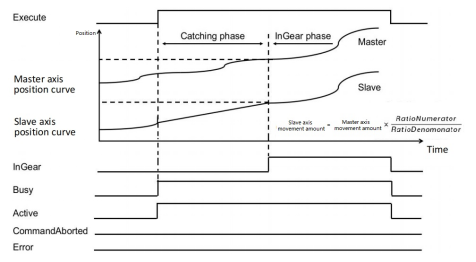
- The gear ratio is negative and the slave axis moves in the reverse direction to the master axis.
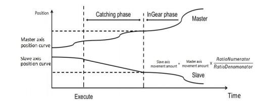
Before reaching synchronization, the slave axis moves according to the maximum acceleration set by the axis as plus or minus speed, and the slave axis velocity is recognized when it is equal to the speed of the master axis multiplied by the gear ratio.
When the speed of the slave axis equals the speed of the master axis multiplied by the gear ratio, the gears are recognized as meshing, and thereafter the slave axis follows the master axis completely.
- Master axis maintains constant velocity before synchronization (Gear instruction is triggered according to 1:1 gear ratio)
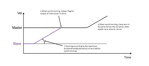
- Master axis moves in variable velocity before synchronization (Gear instruction triggered according to 1:1 gear ratio)
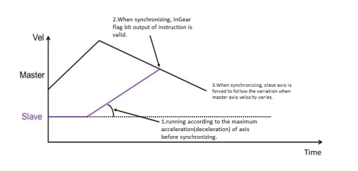
MC_GEAROUT
MC_GEAROUT
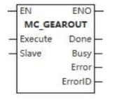
The function block enables the controlled axis to carry out uniform motion at current velocity.
Device used (only a single device can be used, and device splicing and offset are not supported)
| Instruction | Parameter | Devices | Index modification | Pulse expansion | |||||||||||||||||||||||
|---|---|---|---|---|---|---|---|---|---|---|---|---|---|---|---|---|---|---|---|---|---|---|---|---|---|---|---|
| X | Y | M | S | SM | T(bit) | C(bit) | LC(bit) | HSC(bit) | D.b | KnX | KnY | KnM | KnS | T | C | D | R | SD | LC | HSC | K | H | E | [D] | XXP | ||
| MC_GEAROUT | Execute | ● | ● | ● | ● | ● | |||||||||||||||||||||
| Slave | |||||||||||||||||||||||||||
| Done | ● | ● | ● | ● | |||||||||||||||||||||||
| Busy | ● | ● | ● | ● | |||||||||||||||||||||||
| Error | ● | ● | ● | ● | |||||||||||||||||||||||
| ErrorID | |||||||||||||||||||||||||||
Precautions for use of devices
- LC and HSC are signed 32-bit data types;
- T, C, D, R and SD are signed 16-bit data types;
Variable Type Used
| Instruction | Parameter | Variable type | Can be empty or not | Range | Description |
|---|---|---|---|---|---|
| MC_GEAROUT | Execute | BOOL | No | TRUE/FALSE | Enable |
| Slave | WORD | No | 0 to 65535 | Axis number | |
| Done | BOOL | No | TRUE/FALSE | Completion sign | |
| Busy | BOOL | No | TRUE/FALSE | Busy sign | |
| Error | BOOL | No | TRUE/FALSE | Whether there is an error or not | |
| ErrorID | DWORD | No | - | Error code |
Function
- The function block is used for separating the slave axis from the master axis at the velocity ratio and maintaining the motion at the velocity when it separates.
Precautions
- This function block is not available when the axis does not exist.
Sequence diagram
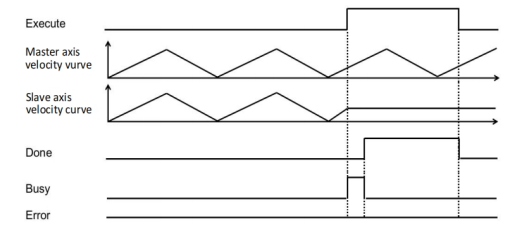
MC_GEARINPOS
MC_GEARINPOS
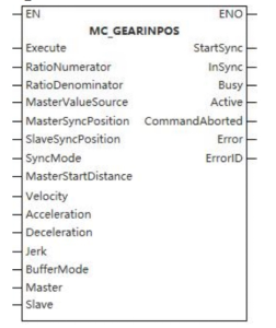
The function block enables the controlled axis to carry out gear motion.
Device used (only a single device can be used, and device splicing and offset are not supported)
| Instruction | Parameter | Devices | Index modification | Pulse expansion | |||||||||||||||||||||||
|---|---|---|---|---|---|---|---|---|---|---|---|---|---|---|---|---|---|---|---|---|---|---|---|---|---|---|---|
| X | Y | M | S | SM | T(bit) | C(bit) | LC(bit) | HSC(bit) | D.b | KnX | KnY | KnM | KnS | T | C | D | R | SD | LC | HSC | K | H | E | [D] | XXP | ||
| MC_GEARINPOS | Execute | ● | ● | ● | ● | ● | |||||||||||||||||||||
| RatioNumerator | |||||||||||||||||||||||||||
| RatioDenominator | |||||||||||||||||||||||||||
| MasterValueSource | |||||||||||||||||||||||||||
| MasterSyncPosition | |||||||||||||||||||||||||||
| SlaveSyncPosition | |||||||||||||||||||||||||||
| SyncMode | |||||||||||||||||||||||||||
| MasterStartDistance | |||||||||||||||||||||||||||
| Velocity | |||||||||||||||||||||||||||
| Acceleration | |||||||||||||||||||||||||||
| Deceleration | |||||||||||||||||||||||||||
| Jerk | |||||||||||||||||||||||||||
| BufferMode | |||||||||||||||||||||||||||
| Master | |||||||||||||||||||||||||||
| Slave | |||||||||||||||||||||||||||
| StartSync | |||||||||||||||||||||||||||
| InSync | ● | ● | ● | ● | |||||||||||||||||||||||
| Busy | ● | ● | ● | ● | |||||||||||||||||||||||
| Active | ● | ● | ● | ● | |||||||||||||||||||||||
| InstructionAborted | ● | ● | ● | ● | |||||||||||||||||||||||
| Error | ● | ● | ● | ● | |||||||||||||||||||||||
| ErrorID | |||||||||||||||||||||||||||
Precautions for use of devices
- LC and HSC are signed 32-bit data types;
- C, D, R and SD are signed 16-bit data types.
Variable Type Used
| Instruction | Parameter | Variable type | Can be empty or not | Range | Description |
|---|---|---|---|---|---|
| MC_GEARINPOS | Execute | BOOL | No | TRUE/FALSE | Enable |
| RatioNumerator | UNIT | No | [-32768,0)U(0,32767] | Gear velocity ratio (numerator) | |
| RatioDenominator | UDINT | No | (0,65535] | Gear velocity ratio (denominator) | |
| MasterValueSource | WORD | No | 0 to 2 | Master axis synchronization source (Instruction value, set value and actual value) | |
| MasterSyncPosition | LREAL | No | -9999999.999999 to 9999999.999999 | Master axis synchronization position | |
| SlaveSyncPosition | LREAL | No | -9999999.999999 to 9999999.999999 | Slave axis synchronization position | |
| SyncMode | WORD | No | 0 to 2 | Synchronous mode (shortest, catchup, slowdown) | |
| MasterStartDistance | LREAL | No | -9999999.999999 to 9999999.999999 (not 0) | Master axis starting distance | |
| Velocity | LREAL | No | 0 to 9999999.999999 (not 0) | Velocity | |
| Acceleration | LREAL | No | 0 to 9999999.999999 (not 0) | Acceleration | |
| Deceleration | LREAL | No | 0 to 9999999.999999 (not 0) | Deceleration | |
| Jerk | LREAL | No | 0 to 9999999.999999 | Jerk | |
| BufferMode | WORD | No | 0 to 5 | Buffer mode selection | |
| Master | WORD | No | 0 to 65535 | Master axis | |
| Slave | WORD | No | 0 to 65535 | Slave axis | |
| StartSync | BOOL | No | TRUE/FALSE | Synchronous identification | |
| InSync | BOOL | No | TRUE/FALSE | Synchronized sign | |
| Busy | BOOL | No | TRUE/FALSE | Busy sign | |
| Active | BOOL | No | TRUE/FALSE | Valid sign | |
| InstructionAborted | BOOL | No | TRUE/FALSE | Abortion sign | |
| Error | BOOL | No | TRUE/FALSE | Whether there is an error or not | |
| ErrorID | DWORD | No | - | Error code |
Function
- The function block is used to achieve the specified velocity ratio between the slave axis and master axis at the specific position through a set maximum velocity, acceleration, deceleration, jerk and synchronous mode.
Precautions
- This function block is not available when the axis does not exist.
Error code
| Error code | Content |
|---|---|
| 4084H | Data beyond the specifiable range was entered. |
Sequence diagram
- After starting the motion, the slave axis performs acceleration and deceleration with the speed obtained by multiplying the axis velocity by the gear ratio as the target velocity;
- The position obtained by ▪ (MasterSyncPosition - MasterStartDistance) is called the start position, and after the master axis reaches this position, the slave axis starts to catching up with the target;
- If the gear ratio is positive, the slave axis moves in the same direction as the master axis.
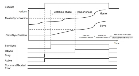
- If the gear ratio is negative, the slave axis moves in the reverse direction to the master axis.
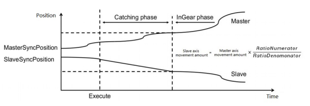
- Before reaching synchronization, the slave axis moves at the maximum acceleration set by the axis as plus or minus speed, and is recognized when the slave axis speed is equal to the speed of the master axis multiplied by the gear ratio.
- When the speed of the slave axis equals the velocity of the master axis multiplied by the gear ratio, the gears are considered to be meshed, and thereafter the slave axis follows the main axis completely.
- The master axis moves at a constant speed until synchronization is achieved (The gear instruction is triggered at a gear ratio of 1:1).
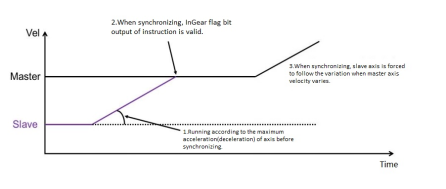
Master axis moves in variable velocity before synchronization (Gear instruction triggered according to 1:1 gear ratio)
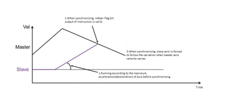
gearInPos carries out the pursuit motion in the following three modes, all following the spindle in gear motion after the target speed has been reached:
- Shortest: catching in constant acceleration mode;
- Catchuo: catching in S-curve;
- Slowdown: catching up in T-curve.
Management functions of axis group motion control
MC_ADDAXISTOGROUP
MC_ADDAXISTOGROUP
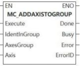
The function block is to add axis to axis group.
Device used (Only a single device can be used, and device splicing and index are not supported)
| Instruction | Parameter | Devices | Index modification | Pulse expansion | |||||||||||||||||||||||
|---|---|---|---|---|---|---|---|---|---|---|---|---|---|---|---|---|---|---|---|---|---|---|---|---|---|---|---|
| X | Y | M | S | SM | T(bit) | C(bit) | LC(bit) | HSC(bit) | D.b | KnX | KnY | KnM | KnS | T | C | D | R | SD | LC | HSC | K | H | E | [D] | XXP | ||
| MC_ADDAXISTOGROUP | Execute | ● | ● | ● | ● | ● | |||||||||||||||||||||
| IdentInGroup | |||||||||||||||||||||||||||
| AxesGroup | |||||||||||||||||||||||||||
| Axis | |||||||||||||||||||||||||||
| Done | ● | ● | ● | ● | |||||||||||||||||||||||
| Busy | ● | ● | ● | ● | |||||||||||||||||||||||
| Error | ● | ● | ● | ● | |||||||||||||||||||||||
Precautions for use of devices
▪LC and HSC are signed 32-bit data types;
▪T, C, D, R and SD are signed 16-bit data types;
Variable type used
| Instruction | Parameter | Variable type | Can it be empty | Range | Description |
|---|---|---|---|---|---|
| MC_ADDAXISTOGROUP | Execute | BOOL | No | TRUE/FALSE | Enable |
| IdentInGroup | WORD | No | [0 to 2] | Axis sequence flag | |
| AxesGroup | WORD | No | [0 to 65535] | Axis group number | |
| Axis | WORD | No | [0 to 65535] | Axis number | |
| Done | BOOL | Yes | TRUE/FALSE | Completion flag | |
| Busy | BOOL | Yes | TRUE/FALSE | Busy flag | |
| Error | BOOL | Yes | TRUE/FALSE | Whether there is an error or not | |
| ErrorID | DWORD | Yes | - | Error code (Please check【8. 10 Error Code Cross-reference Table】) |
Features
▪The rising edge of Execute triggers and Axis is added to Axes Group. Instructions are not buffered and axis do not move;
▪IndentInGroup is a flag of the adding axis order to axis group.
Error code
| Error code | Content |
|---|---|
| 4084H | Data beyond the specifiable range was input. |
Sequence diagram
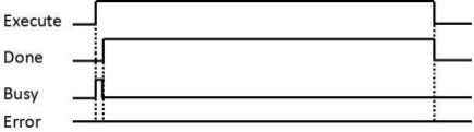
MC_REMOVEAXISFROMGROUP
MC_REMOVEAXISFROMGROUP
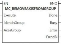
This function block removes axis from an axis group.
Device used (Only a single device can be used, and device splicing and index are not supported)
| Instruction | Parameter | Devices | Index modification | Pulse expansion | |||||||||||||||||||||||
|---|---|---|---|---|---|---|---|---|---|---|---|---|---|---|---|---|---|---|---|---|---|---|---|---|---|---|---|
| X | Y | M | S | SM | T(bit) | C(bit) | LC(bit) | HSC(bit) | D.b | KnX | KnY | KnM | KnS | T | C | D | R | SD | LC | HSC | K | H | E | [D] | XXP | ||
| MC_REMOVEAXISFROMGROUP | Execute | ● | ● | ● | ● | ● | |||||||||||||||||||||
| IdentInGroup | |||||||||||||||||||||||||||
| AxesGroup | |||||||||||||||||||||||||||
| Done | ● | ● | ● | ● | |||||||||||||||||||||||
| Busy | ● | ● | ● | ● | |||||||||||||||||||||||
| Error | ● | ● | ● | ● | |||||||||||||||||||||||
| ErrorID | |||||||||||||||||||||||||||
Precautions for use of devices
▪LC and HSC are signed 32-bit data types;
▪T, C, D, R and SD are signed 16-bit data types;
Variable type used
| Instruction | Parameter | Variable type | Can it be empty | Range | Description |
|---|---|---|---|---|---|
| MC_REMOVEAXISFROMGROUP | Execute | BOOL | No | TRUE/FALSE | Enable |
| IdentInGroup | WORD | No | [0 to 2] | Axis sequence flag | |
| AxesGroup | WORD | No | [0 to 65535] | Axis group number | |
| Done | BOOL | Yes | TRUE/FALSE | Completion flag | |
| Busy | BOOL | Yes | TRUE/FALSE | Busy flag | |
| Error | BOOL | Yes | TRUE/FALSE | Whether there is an error or not | |
| ErrorID | DWORD | Yes | - | Error code (Please check【8. 10 Error Code Cross-reference Table】) |
Features
▪This function block removes axis from AxesGroup with serial number marked by IdentInGroup, which are not cached and do not move.
Error code
| Error code | Content |
|---|---|
| 4084H | Data beyond the specifiable range was input. |
Sequence diagram
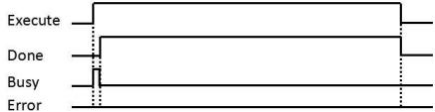
MC_UNGROUPALLAXES
MC_UNGROUPALLAXES
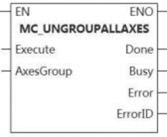
This function block removes all the axes from an axis group.
Device used (Only a single device can be used, and device splicing and index are not supported)
| Instruction | Parameter | Devices | Index modification | Pulse expansion | |||||||||||||||||||||||
|---|---|---|---|---|---|---|---|---|---|---|---|---|---|---|---|---|---|---|---|---|---|---|---|---|---|---|---|
| X | Y | M | S | SM | T(bit) | C(bit) | LC(bit) | HSC(bit) | D.b | KnX | KnY | KnM | KnS | T | C | D | R | SD | LC | HSC | K | H | E | [D] | XXP | ||
| MC_UNGROUPALLAXES | Execute | ● | ● | ● | ● | ● | |||||||||||||||||||||
| AxesGroup | |||||||||||||||||||||||||||
| Done | ● | ● | ● | ● | |||||||||||||||||||||||
| BusY | ● | ● | ● | ● | |||||||||||||||||||||||
| Error | ● | ● | ● | ● | |||||||||||||||||||||||
| ErrorID | |||||||||||||||||||||||||||
Precautions for use of devices
▪LC and HSC are signed 32-bit data types;
▪T, C, D, R and SD are signed 16-bit data types;
Variable type used
| Instruction | Parameter | Variable type | Can it be empty | Range | Description |
|---|---|---|---|---|---|
| MC_UNGROUPALLAXES | Execute | BOOL | No | TRUE/FALSE | Enable |
| AxesGroup | WORD | No | [0 to 65535] | Axis group number | |
| Done | BOOL | Yes | TRUE/FALSE | Completion flag | |
| BusY | BOOL | Yes | TRUE/FALSE | Busy flag | |
| Error | BOOL | Yes | TRUE/FALSE | Whether there is an error or not | |
| ErrorID | DWORD | Yes | - | Error code (Please check【8. 10 Error Code Cross-reference Table】) |
Features
▪Delete all axes from AxesGroup. Not be buffered and not move.
Error code
| Error code | Content |
|---|---|
| 4084H | Input data beyond the specifiable range |
Sequence diagram
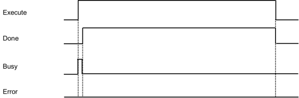
MC_GROUPENABLE
MC_GROUPENABLE
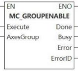
The function block is axis group enabled.
Device used (Only a single device can be used, and device splicing and index are not supported)
| Instruction | Parameter | Devices | Index modification | Pulse expansion | |||||||||||||||||||||||
|---|---|---|---|---|---|---|---|---|---|---|---|---|---|---|---|---|---|---|---|---|---|---|---|---|---|---|---|
| X | Y | M | S | SM | T(bit) | C(bit) | LC(bit) | HSC(bit) | D.b | KnX | KnY | KnM | KnS | T | C | D | R | SD | LC | HSC | K | H | E | [D] | XXP | ||
| MC_SAVECAMTABLE | Execute | ● | ● | ● | ● | ● | |||||||||||||||||||||
| AxesGroup | |||||||||||||||||||||||||||
| Done | ● | ● | ● | ● | |||||||||||||||||||||||
| Busy | ● | ● | ● | ● | |||||||||||||||||||||||
| Error | ● | ● | ● | ● | |||||||||||||||||||||||
| ErrorID | |||||||||||||||||||||||||||
Precautions for use of devices
▪LC and HSC are signed 32-bit data types;
▪T, C, D, R and SD are signed 16-bit data types.
Variable type used
| Instruction | Parameter | Variable type | Can it be empty | Range | Description |
| MC_GROUPENABLE | Execute | BOOL | No | TRUE/FALSE | Enable |
| AxesGroup | WORD | No | [0 to 65535] | Axis group number | |
| Done | BOOL | Yes | TRUE/FALSE | Completion flag | |
| Busy | BOOL | Yes | TRUE/FALSE | Busy flag | |
| Error | BOOL | Yes | TRUE/FALSE | Whether there is an error or not | |
| ErrorID | DWORD | Yes | - | Error code (Please check【8. 10 Error Code Cross-reference Table】) |
Features
▪Enable axis group to run on the Execute rising edge.
Error code
| Error code | Content |
|---|---|
| 4084H | Input data beyond the specifiable range |
MC_GROUPDISABLE
MC_GROUPDISABLE
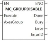
This function block is axis group disabled.
Device used (Only a single device can be used, an d device splicing and index are not supported)
| Instruction | Parameter | Devices | Index modification | Pulse expansion | |||||||||||||||||||||||
|---|---|---|---|---|---|---|---|---|---|---|---|---|---|---|---|---|---|---|---|---|---|---|---|---|---|---|---|
| X | Y | M | S | SM | T(bit) | C(bit) | LC(bit) | HSC(bit) | D.b | KnX | KnY | KnM | KnS | T | C | D | R | SD | LC | HSC | K | H | E | [D] | XXP | ||
| MC_GROUPDISABLE | Execute | ● | ● | ● | ● | ● | |||||||||||||||||||||
| AxesGroup | |||||||||||||||||||||||||||
| Done | ● | ● | ● | ● | |||||||||||||||||||||||
| Busy | ● | ● | ● | ● | |||||||||||||||||||||||
| Error | ● | ● | ● | ● | |||||||||||||||||||||||
| ErrorID | |||||||||||||||||||||||||||
Precautions for use of devices
▪LC and HSC are signed 32-bit data types;
▪T, C, D, R and SD are signed 16-bit data types.
Variable type used
| Instruction | Parameter | Variable type | Can it be empty | Range | Description |
|---|---|---|---|---|---|
| MC_GROUPDISABLE | Execute | BOOL | No | TRUE/FALSE | Enable |
| AxesGroup | WORD | No | [0 to 65535] | Axis group number | |
| Done | BOOL | Yes | TRUE/FALSE | Completion flag | |
| Busy | BOOL | Yes | TRUE/FALSE | Busy flag | |
| Error | BOOL | Yes | TRUE/FALSE | Whether there is an error or not | |
| ErrorID | DWORD | Yes | - | Error code (Please check【8. 10 Error Code Cross-reference Table】) |
Features
▪On the Execute rising edge, disable the axis group.
Error code
| Error code | Content |
|---|---|
| 4084H | Input data beyond the specifiable range |
MC_GROUPREDACTUALPOSITION
MC_GROUPREADACTUALPOSITION
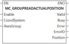
This function block is to read the actual position of each axis from the axis group.
Device used (Only a single device can be used, and device splicing and index are not supported)
| Instruction | Parameter | Devices | Index modification | Pulse expansion | |||||||||||||||||||||||
|---|---|---|---|---|---|---|---|---|---|---|---|---|---|---|---|---|---|---|---|---|---|---|---|---|---|---|---|
| X | Y | M | S | SM | T(bit) | C(bit) | LC(bit) | HSC(bit) | D.b | KnX | KnY | KnM | KnS | T | C | D | R | SD | LC | HSC | K | H | E | [D] | XXP | ||
| MC_GROUPREADA CTUALPOSITION | Enable | ● | ● | ● | ● | ● | |||||||||||||||||||||
| CoordSystem | |||||||||||||||||||||||||||
| AxesGroup | |||||||||||||||||||||||||||
| Valid | ● | ● | ● | ● | |||||||||||||||||||||||
| Busy | ● | ● | ● | ● | |||||||||||||||||||||||
| Error | ● | ● | ● | ● | |||||||||||||||||||||||
| ErrorID | |||||||||||||||||||||||||||
| Position | |||||||||||||||||||||||||||
Precautions for use of devices
▪LC and HSC are signed 32-bit data types;
▪T, C, D, R and SD are signed 16-bit data types.
Variable type used
| Instruction | Parameter | Variable type | Can it be empty | Range | Description |
|---|---|---|---|---|---|
| MC_GROUPREADACTUALPOSITION | Enable | BOOL | No | TRUE/FALSE | Enable |
| CoordSystem | WORD | Yes | 0 | Coordinate system | |
| AxesGroup | WORD | No | [0 to 65535] | Axis group number | |
| Valid | BOOL | Yes | TRUE/FALSE | Completion flag | |
| Busy | BOOL | Yes | TRUE/FALSE | Busy flag | |
| Error | BOOL | Yes | TRUE/FALSE | Whether there is an error or not | |
| ErrorID | DWORD | Yes | - | Error code (Please check【8. 10 Error Code Cross-reference Table】) | |
| Position | LREAL array | Yes | Position |
Features
- When Enable= true, the position of each axis of the selected axis group in the selected coordinate system is continuously returned.
Error code
| Error code | Content |
|---|---|
| 4084H | Input data beyond the specifiable range |
MC_GROUPREADACTUALVELOCITY
MC_GROUPREADACTUALVELOCITY
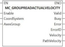
![]()
This function block is to read the actual velocity of each axis from the axis group.
Device used (Only a single device can be used, and device splicing and index are not supported)
| Instruction | Parameter | Devices | Index modification | Pulse expansion | |||||||||||||||||||||||
|---|---|---|---|---|---|---|---|---|---|---|---|---|---|---|---|---|---|---|---|---|---|---|---|---|---|---|---|
| X | Y | M | S | SM | T(bit) | C(bit) | LC(bit) | HSC(bit) | D.b | KnX | KnY | KnM | KnS | T | C | D | R | SD | LC | HSC | K | H | E | [D] | XXP | ||
| MC_GROUPREADACTUALVELOCITY | Enable | ● | ● | ● | ● | ● | |||||||||||||||||||||
| CoordSystem | |||||||||||||||||||||||||||
| AxesGroup | |||||||||||||||||||||||||||
| Valid | ● | ● | ● | ● | |||||||||||||||||||||||
| Busy | ● | ● | ● | ● | |||||||||||||||||||||||
| Error | ● | ● | ● | ● | |||||||||||||||||||||||
| ErrorID | |||||||||||||||||||||||||||
| Velocity | |||||||||||||||||||||||||||
| PathVelocity | |||||||||||||||||||||||||||
Precautions for use of devices
▪LC and HSC are signed 32-bit data types;
▪T, C, D, R and SD are signed 16-bit data types;
Variable type used
| Instruction | Parameter | Variable type | Can it be empty | Range | Description |
|---|---|---|---|---|---|
| MC_GROUPREADACTUALVELOCITY | Enable | BOOL | No | TRUE/FALSE | Enable |
| CoordSystem | WORD | Yes | 0 | Coordinate system | |
| AxesGroup | WORD | No | [0 to 65535] | Axis group number | |
| Valid | BOOL | Yes | TRUE/FALSE | Completion flag | |
| Busy | BOOL | Yes | TRUE/FALSE | Busy flag | |
| Error | BOOL | Yes | TRUE/FALSE | Whether there is an error or not | |
| ErrorID | DWORD | Yes | - | Error code (Please check【8. 10 Error Code Cross-reference Table】) | |
| Velocity | LREAL array | Yes | Velocity | ||
| PathVelocity | LREAL | Yes | Path velocity |
Features
When Enable=true, the velocity of each axis and the current TCP path velocity (the result of combined velocity) of the selected axis group in the selected coordinate system are continuously returned.
Error code
| Error code | Content |
|---|---|
| 4084H | Data beyond the specifiable range was input. |
MC_GROUPREADERROR
MC_GROUPREADERROR
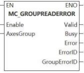
![]()
The function block is axis group to read error.
Device used (Only a single device can be used, and device splicing and index are not supported)
| Instruction | Parameter | Devices | Index modification | Pulse expansion | |||||||||||||||||||||||
|---|---|---|---|---|---|---|---|---|---|---|---|---|---|---|---|---|---|---|---|---|---|---|---|---|---|---|---|
| X | Y | M | S | SM | T(bit) | C(bit) | LC(bit) | HSC(bit) | D.b | KnX | KnY | KnM | KnS | T | C | D | R | SD | LC | HSC | K | H | E | [D] | XXP | ||
| MC_GROUPREADERROR | Enable | ● | ● | ● | ● | ● | |||||||||||||||||||||
| AxesGroup | |||||||||||||||||||||||||||
| Valid | ● | ● | ● | ● | |||||||||||||||||||||||
| Busy | ● | ● | ● | ● | |||||||||||||||||||||||
| Error | ● | ● | ● | ● | |||||||||||||||||||||||
| ErrorID | |||||||||||||||||||||||||||
| GroupErrorID | |||||||||||||||||||||||||||
Precautions for use of devices
▪LC and HSC are signed 32-bit data types;
▪T, C, D, R and SD are signed 16-bit data types;
Variable type used
| Instruction | Parameter | Variable type | Can it be empty | Range | Description |
|---|---|---|---|---|---|
| MC_GROUPREADERROR | Enable | BOOL | No | TRUE/FALSE | Enable |
| AxesGroup | WORD | No | [0 to 65535] | Axis group number | |
| Valid | BOOL | Yes | TRUE/FALSE | Completion flag | |
| Busy | BOOL | Yes | TRUE/FALSE | Busy flag | |
| Error | BOOL | Yes | TRUE/FALSE | Whether there is an error or not | |
| ErrorID | DWORD | Yes | - | Error code (Please check【8. 10 Error Code Cross-reference Table】) | |
| GroupErrorID | DWROD | Yes | Axis group error code |
Features
▪When Enable= true, read the axis group error status.
Error code
| Error code | Content |
|---|---|
| 4084H | Input data beyond the specifiable range |
MC_GROUPREADSTATUS
MC_GROUPREADSTATUS
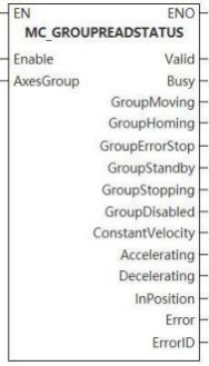
This function block reads the status of the currently activated axis group.
Device used (Only a single device can be used, and device splicing and index are not supported)
| Instruction | Parameter | Devices | Index modification | Pulse expansion | |||||||||||||||||||||||
|---|---|---|---|---|---|---|---|---|---|---|---|---|---|---|---|---|---|---|---|---|---|---|---|---|---|---|---|
| X | Y | M | S | SM | T(bit) | C(bit) | LC(bit) | HSC(bit) | D.b | KnX | KnY | KnM | KnS | T | C | D | R | SD | LC | HSC | K | H | E | [D] | XXP | ||
| MC_GROUPREADERROR | Enable | ● | ● | ● | ● | ● | |||||||||||||||||||||
| AxesGroup | |||||||||||||||||||||||||||
| Valid | ● | ● | ● | ● | |||||||||||||||||||||||
| Busy | ● | ● | ● | ● | |||||||||||||||||||||||
| Error | ● | ● | ● | ● | |||||||||||||||||||||||
| ErrorID | |||||||||||||||||||||||||||
| GroupErrorID | |||||||||||||||||||||||||||
Precautions for use of devices
▪LC and HSC are signed 32-bit data types;
▪T, C, D, R and SD are signed 16-bit data types;
Variable type used
| Instruction | Parameter | Variable type | Can it be empty | Range | Description |
|---|---|---|---|---|---|
| MC_GROUPREADERROR | Enable | BOOL | No | TRUE/FALSE | Enable |
| AxesGroup | WORD | No | [0 to 65535] | Axis group number | |
| Valid | BOOL | Yes | TRUE/FALSE | Completion flag | |
| Busy | BOOL | Yes | TRUE/FALSE | Busy flag | |
| Error | BOOL | Yes | TRUE/FALSE | Whether there is an error or not | |
| ErrorID | DWORD | Yes | - | Error code (Please check【8. 10 Error Code Cross-reference Table】) | |
| GroupErrorID | DWROD | Yes | Axis group error code |
Features
▪When Enable= true, the status of the enabled axis group is continuously returned, and its status is set and marked by the output flag;
▪ConstantVelocity is set to ON when moving at constant velocity on the command path. Accelerating and decelerating is set to ON when the velocity increases or decreases on the command path.
▪ InPosition is set to ON when reach the target position.
Error code
| Error code | Content |
|---|---|
| 4084H | Input data beyond the specifiable range |
MC_GROUPRESET
MC_GROUPRESET
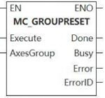
The function block is axis group reset.
Device used (Only a single device can be used, and device splicing and index are not supported)
| Instruction | Parameter | Devices | Index modification | Pulse expansion | |||||||||||||||||||||||
|---|---|---|---|---|---|---|---|---|---|---|---|---|---|---|---|---|---|---|---|---|---|---|---|---|---|---|---|
| X | Y | M | S | SM | T(bit) | C(bit) | LC(bit) | HSC(bit) | D.b | KnX | KnY | KnM | KnS | T | C | D | R | SD | LC | HSC | K | H | E | [D] | XXP | ||
| MC_GROUPRESET | Execute | ● | ● | ● | ● | ● | |||||||||||||||||||||
| AxesGroup | |||||||||||||||||||||||||||
| Done | ● | ● | ● | ● | |||||||||||||||||||||||
| Busy | ● | ● | ● | ● | |||||||||||||||||||||||
| Error | ● | ● | ● | ● | |||||||||||||||||||||||
| ErrorID | |||||||||||||||||||||||||||
Precautions for use of devices
▪LC and HSC are signed 32-bit data types;
▪T, C, D, R and SD are signed 16-bit data types.
Variable type used
| Instruction | Parameter | Variable type | Can it be empty | Range | Description |
| MC_GROUPRESET | Execute | BOOL | No | TRUE/FALSE | Enable |
| AxesGroup | WORD | No | [0 to 65535] | Axis group number | |
| Done | BOOL | Yes | TRUE/FALSE | Completion flag | |
| Busy | BOOL | Yes | TRUE/FALSE | Busy flag | |
| Error | BOOL | Yes | TRUE/FALSE | Whether there is an error or not | |
| ErrorID | DWORD | Yes | - | Error code (Please check【8. 10 Error Code Cross-reference Table】) |
Features
▪Reset the axis group from the error status to the enabled status when on the Execute rising edge, which is similar with the single-axis MC_Reset.
Error code
| Error code | Content |
|---|---|
| 4084H | Input data beyond the specifiable range |
MC_GROUPREADACTUALACCELERATION
MC_GROUPREADACTUALACCELERATION
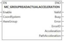
This function block is to read the actual acceleration of each axis from the axis group.
Device used (Only a single device can be used, and device splicing and index are not supported)
| Instruction | Parameter | Devices | Index modification | Pulse expansion | |||||||||||||||||||||||
|---|---|---|---|---|---|---|---|---|---|---|---|---|---|---|---|---|---|---|---|---|---|---|---|---|---|---|---|
| X | Y | M | S | SM | T(bit) | C(bit) | LC(bit) | HSC(bit) | D.b | KnX | KnY | KnM | KnS | T | C | D | R | SD | LC | HSC | K | H | E | [D] | XXP | ||
MC_GROUPREADACTUALACCELERATION
| Enable | ● | ● | ● | ● | ● | |||||||||||||||||||||
| CoordSystem | |||||||||||||||||||||||||||
| AxesGroup | |||||||||||||||||||||||||||
| Valid | ● | ● | ● | ● | |||||||||||||||||||||||
| Busy | ● | ● | ● | ● | |||||||||||||||||||||||
| Error | ● | ● | ● | ● | |||||||||||||||||||||||
| ErrorID | |||||||||||||||||||||||||||
| Acceleration | |||||||||||||||||||||||||||
| PathAcceleration | |||||||||||||||||||||||||||
Precautions for use of devices
▪LC and HSC are signed 32-bit data types;
▪T, C, D, R and SD are signed 16-bit data types;
Variable type used
| Instruction | Parameter | Variable type | Can it be empty | Range | Description |
|---|---|---|---|---|---|
| MC_GROUPREADACTUALACCELERATION | Enable | BOOL | No | TRUE/FALSE | Enable |
| CoordSystem | WORD | Yes | 0 | Coordinate system | |
| AxesGroup | WORD | No | [0 to 65535] | Axis group number | |
| Valid | BOOL | Yes | TRUE/FALSE | Whether the input is valid or not | |
| Busy | BOOL | Yes | TRUE/FALSE | Busy flag | |
| Error | BOOL | Yes | TRUE/FALSE | Whether there is an error or not | |
| ErrorID | DWORD | Yes | - | Error code (Please check【8. 10 Error Code Cross-reference Table】) | |
| Acceleration | LREAL array | Yes | Acceleration | ||
| PathAcceleration | LREAL | Yes | Path acceleration |
Features
▪When Enable=true, the acceleration of each axis and the current TCP path acceleration (The result of combined acceleration) of the selected axis group in the selected coordinate system are continuously returned.
Error code
| Error code | Content |
|---|---|
| 4084H | Data beyond the specifiable range was input. |
Axis group motion Function Blocks
MC_GROUPSTOP
MC_GROUPSTOP
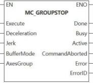
The function block is use to stop axis group.
Device used (Only a single device can be used, and device splicing and index are not supported)
| Instruction | Parameter | Devices | Index modification | Pulse expansion | |||||||||||||||||||||||
|---|---|---|---|---|---|---|---|---|---|---|---|---|---|---|---|---|---|---|---|---|---|---|---|---|---|---|---|
| X | Y | M | S | SM | T(bit) | C(bit) | LC(bit) | HSC(bit) | D.b | KnX | KnY | KnM | KnS | T | C | D | R | SD | LC | HSC | K | H | E | [D] | XXP | ||
| MC_GROUPSTOP | Execute | ● | ● | ● | ● | ● | |||||||||||||||||||||
| Deceleration | |||||||||||||||||||||||||||
| Jerk | |||||||||||||||||||||||||||
| AxesGroup | |||||||||||||||||||||||||||
| Done | ● | ● | ● | ● | |||||||||||||||||||||||
| Busy | ● | ● | ● | ● | |||||||||||||||||||||||
| Active | ● | ● | ● | ● | |||||||||||||||||||||||
| InstructionAborted | ● | ● | ● | ● | |||||||||||||||||||||||
| Error | ● | ● | ● | ● | |||||||||||||||||||||||
| ErrorID | |||||||||||||||||||||||||||
Precautions for use of devices
▪LC and HSC are signed 32-bit data types;
▪T, C, D, R and SD are signed 16-bit data types;
Variable type used
| Instruction | Parameter | Variable type | Can it be empty | Range | Description |
|---|---|---|---|---|---|
| MC_GROUPSTOP | Execute | BOOL | No | TRUE/FALSE | Enable |
| Deceleration | LREAL | No | [0 to 999999999. 999999] | Deceleration | |
| Jerk | LREAL | Yes | [0 to 999999999. 999999] | Jerk | |
| AxesGroup | WORD | No | [0 to 65535] | Axis group number | |
| Done | BOOL | Yes | TRUE/FALSE | Completion flag | |
| Busy | BOOL | Yes | TRUE/FALSE | Busy flag | |
| Active | BOOL | Yes | TRUE/FALSE | Valid flag | |
| InstructionAborted | BOOL | Yes | TRUE/FALSE | Abortion flag | |
| Error | BOOL | Yes | TRUE/FALSE | Whether there is an error or not | |
| ErrorID | DWORD | Yes | - | Error code (Please check【8. 10 Error Code Cross-reference Table】) |
Features
▪When on the Execute rising edge, the axis group decelerate to stop and any functional block being executed is stopped. When Execute=true, the axis group is on the stop status and cannot execute other axis group motion instruction.
▪The velocity of axis group is zero. Done is set to ON. If Execute=false, return to the normal axis group enabling status;
▪Only MC_GroupDisable can be used to interrupt axis group.
Error code
| Error code | Content |
|---|---|
| 4084H | Input data beyond the specifiable range |
MC_GROUPHALT
MC_GROUPHALT
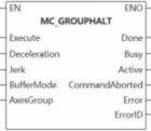
The function block is to halt axis group.
Device used (Only a single device can be used, and device splicing and index are not supported)
| Instruction | Parameter | Devices | Index modification | Pulse expansion | |||||||||||||||||||||||
|---|---|---|---|---|---|---|---|---|---|---|---|---|---|---|---|---|---|---|---|---|---|---|---|---|---|---|---|
| X | Y | M | S | SM | T(bit) | C(bit) | LC(bit) | HSC(bit) | D.b | KnX | KnY | KnM | KnS | T | C | D | R | SD | LC | HSC | K | H | E | [D] | XXP | ||
| MC_GROUPHALT | Execute | ● | ● | ● | ● | ● | |||||||||||||||||||||
| Deceleration | |||||||||||||||||||||||||||
| Jerk | |||||||||||||||||||||||||||
| AxesGroup | |||||||||||||||||||||||||||
| Done | ● | ● | ● | ● | |||||||||||||||||||||||
| Busy | ● | ● | ● | ● | |||||||||||||||||||||||
| Active | ● | ● | ● | ● | |||||||||||||||||||||||
| InstructionAborted | ● | ● | ● | ● | |||||||||||||||||||||||
| Error | ● | ● | ● | ● | |||||||||||||||||||||||
| ErrorID | |||||||||||||||||||||||||||
Precautions for use of devices
▪LC and HSC are signed 32-bit data types;
▪T, C, D, R and SD are signed 16-bit data types;
Variable type used
| Instruction | Parameter | Variable type | Can it be empty | Range | Description |
|---|---|---|---|---|---|
| MC_GROUPHALT | Execute | BOOL | No | TRUE/FALSE | Enable |
| Deceleration | LREAL | No | [0 to 999999999. 999999] | Deceleration | |
| Jerk | LREAL | Yes | [0 to 999999999. 999999] | Jerk | |
| AxesGroup | WORD | No | [0 to 65535] | Axis group number | |
| Done | BOOL | Yes | TRUE/FALSE | Completion flag | |
| Busy | BOOL | Yes | TRUE/FALSE | Busy flag | |
| Active | BOOL | Yes | TRUE/FALSE | Valid flag | |
| InstructionAborted | BOOL | Yes | TRUE/FALSE | Abortion flag | |
| Error | BOOL | Yes | TRUE/FALSE | Whether there is an error or not | |
| ErrorID | DWORD | Yes | - | Error code (Please check【8. 10 Error Code Cross-reference Table】) |
Features
▪When on the Execute rising edge, the axis group decelerate to stop, any function block being executed is stopped, and the axis group velocity is 0. Done is set to on;
▪Unbuffered mode: During axis group deceleration, if another function block with mcAborting buffer mode is executed, the current function block is interrupted and the new function block is executed immediately.
Error code
| Error code | Content |
|---|---|
| 4084H | Data beyond the specifiable range was input. |
MC_MOVELINEARABSOLUTE
MC_MOVELINEARABSOLUTE
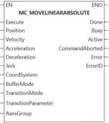
This function block is absolute position linear interpolation.
Device used (Only a single device can be used, and device splicing and index are not supported)
| Instruction | Parameter | Devices | Index modification | Pulse expansion | |||||||||||||||||||||||
|---|---|---|---|---|---|---|---|---|---|---|---|---|---|---|---|---|---|---|---|---|---|---|---|---|---|---|---|
| X | Y | M | S | SM | T(bit) | C(bit) | LC(bit) | HSC(bit) | D.b | KnX | KnY | KnM | KnS | T | C | D | R | SD | LC | HSC | K | H | E | [D] | XXP | ||
| MC_MOVELINEARABSOLUTE | Execute | ● | ● | ● | ● | ● | |||||||||||||||||||||
| Position | |||||||||||||||||||||||||||
| Velocity | |||||||||||||||||||||||||||
| Acceleration | |||||||||||||||||||||||||||
| Deceleration | |||||||||||||||||||||||||||
| Jerk | |||||||||||||||||||||||||||
| CoordSystem | |||||||||||||||||||||||||||
| BufferMode | |||||||||||||||||||||||||||
| TransitionMode | |||||||||||||||||||||||||||
| TransitionParameter | |||||||||||||||||||||||||||
| AxesGroup | |||||||||||||||||||||||||||
| Done | ● | ● | ● | ● | |||||||||||||||||||||||
| Busy | ● | ● | ● | ● | |||||||||||||||||||||||
| Active | ● | ● | ● | ● | |||||||||||||||||||||||
| InstructionAborted | ● | ● | ● | ● | |||||||||||||||||||||||
| Error | ● | ● | ● | ● | |||||||||||||||||||||||
| ErrorID | |||||||||||||||||||||||||||
Precautions for use of devices
▪LC and HSC are signed 32-bit data types;
▪T, C, D, R and SD are signed 16-bit data types;
Variable type used
| Instruction | Parameter | Variable type | Can it be empty | Range | Description |
|---|---|---|---|---|---|
MC_MOVELINEARABSOLUTE | Execute | BOOL | No | TRUE/FALSE | Enable |
| Position | LREAL array | No | - | Position | |
| Velocity | LREAL | No | [0 to 999999999. 999999] | Velocity | |
| Acceleration | LREAL | No | [0 to 999999999. 999999] | Acceleration | |
| Deceleration | LREAL | No | [0 to 999999999. 999999] | Deceleration | |
| Jerk | LREAL | Yes | [0 to 999999999. 999999] | Jerk is valid in S curve only. | |
| CoordSystem | WORD | Yes | 0 | Coordinate system | |
| BufferMode | WORD | Yes | [0 to 1] | Please check [8.9.5 Mode selection description] for more details. | |
| TransitionMode | WORD | Yes | [0 to 2] | Please check [8.9.4 Transition mode description] for more details. | |
| TransitionParameter | LREAL | Yes | [0 to 999999999. 999999] | Please check [8.9.4 Transition mode description] for more details on transition parameter. | |
| AxesGroup | WORD | No | [0 to 65535] | Axis group number | |
| Done | BOOL | Yes | TRUE/FALSE | Completion flag | |
| Busy | BOOL | Yes | TRUE/FALSE | Busy flag | |
| Active | BOOL | Yes | TRUE/FALSE | Valid flag | |
| InstructionAborted | BOOL | Yes | TRUE/FALSE | Abortion flag | |
| Error | BOOL | Yes | TRUE/FALSE | Whether there is an error or not | |
| ErrorID | DWORD | Yes | - | Error code (Please check【8. 10 Error Code Cross-reference Table】) |
Features
▪This function block executes linear interpolation motion, and puts the actual TCP position to the absolute position specified by a specific CoordSystem.
Error code
| Error code | Content |
|---|---|
| 4084H | Input data beyond the specifiable range |

MC_MOVELINEARRELATIVE
MC_MOVELINEARRELATIVE
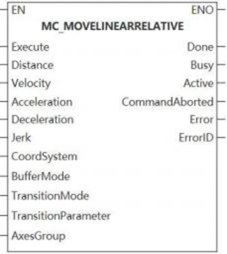
This function block is relative position linear interpolation.
Device used (Only a single device can be used, and device splicing and index are not supported)
| Instruction | Parameter | Devices | Index modification | Pulse expansion | |||||||||||||||||||||||||
|---|---|---|---|---|---|---|---|---|---|---|---|---|---|---|---|---|---|---|---|---|---|---|---|---|---|---|---|---|---|
| X | Y | M | S | SM | T(bit) | C(bit) | LC(bit) | HSC(bit) | D.b | KnX | KnY | KnM | KnS | T | C | D | R | SD | LC | HSC | K | H | E | [D] | XXP | ||||
| MC_MOVELINEARRELATIVE | Execute | ● | ● | ● | ● | ● | |||||||||||||||||||||||
| Distance | |||||||||||||||||||||||||||||
| Velocity | |||||||||||||||||||||||||||||
| Acceleration | |||||||||||||||||||||||||||||
| Deceleration | |||||||||||||||||||||||||||||
| Jerk | |||||||||||||||||||||||||||||
| CoordSystem | |||||||||||||||||||||||||||||
| BufferMode | |||||||||||||||||||||||||||||
| TransitionMode | |||||||||||||||||||||||||||||
| TransitionParameter | |||||||||||||||||||||||||||||
| AxesGroup | |||||||||||||||||||||||||||||
| Done | ● | ● | ● | ● | |||||||||||||||||||||||||
| Busy | ● | ● | ● | ● | |||||||||||||||||||||||||
| Active | ● | ● | ● | ● | |||||||||||||||||||||||||
| InstructionAborted | ● | ● | ● | ● | |||||||||||||||||||||||||
| Error | ● | ● | ● | ● | |||||||||||||||||||||||||
| ErrorID | |||||||||||||||||||||||||||||
Precautions for use of devices
▪LC and HSC are signed 32-bit data types;
▪T, C, D, R and SD are signed 16-bit data types.
Variable type used
| Instruction | Parameter | Variable type | Can it be empty | Range | Description |
|---|---|---|---|---|---|
| MC_MOVELINEARRELATIVE | Execute | BOOL | No | TRUE/FALSE | Enable |
| Distance | LREAL array | No | - | Position | |
| Velocity | LREAL | No | [0 to 999999999. 999999] | Velocity | |
| Acceleration | LREAL | No | [0 to 999999999. 999999] | Acceleration | |
| Deceleration | LREAL | No | [0 to 999999999. 999999] | Deceleration | |
| Jerk | LREAL | Yes | [0 to 999999999. 999999] | Jerk: Only the axis group S-curve is valid. | |
| CoordSystem | WORD | Yes | - | Coordinate system | |
| BufferMode | WORD | Yes | [0 to 1] | Please check [8.9.5 Mode selection description] for more details. | |
| TransitionMode | WORD | Yes | [0 to 2] | Please check [8.9.4 Transition mode description] for more details. | |
| TransitionParameter | LREAL | Yes | [0 to 999999999. 999999] | Please check [8.9.4 Transition mode description] for more details on transition parameter. | |
| AxesGroup | WORD | No | [0 to 65535] | Axis group number | |
| Done | BOOL | Yes | TRUE/FALSE | Completion flag | |
| Busy | BOOL | Yes | TRUE/FALSE | Busy flag | |
| Active | BOOL | Yes | TRUE/FALSE | Valid flag | |
| InstructionAborted | BOOL | Yes | TRUE/FALSE | Abortion flag | |
| Error | BOOL | Yes | TRUE/FALSE | Whether there is an error or not | |
| ErrorID | DWORD | Yes | - | Error code (Please check【8. 10 Error Code Cross-reference Table】) |
Features
▪This function block executes line interpolation motion, and puts the actual TCP position to the absolute position specified by a specific coordsystem.
Error code
| Error code | Content |
|---|---|
| 4084H | Input data beyond the specifiable range |
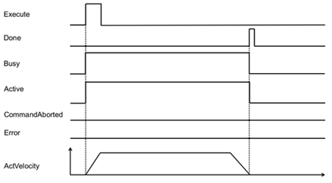
MC_MOVECIRCULARABSOLUTE
MC_MOVECIRCULARABSOLUTE
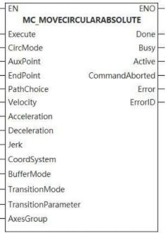
The function block is absolute position circular interpolation.
Device used (Only a single device can be used, and device splicing and index are not supported)
| Instruction | Parameter | Devices | Index modification | Pulse expansion | |||||||||||||||||||||||
|---|---|---|---|---|---|---|---|---|---|---|---|---|---|---|---|---|---|---|---|---|---|---|---|---|---|---|---|
| X | Y | M | S | SM | T(bit) | C(bit) | LC(bit) | HSC(bit) | D.b | KnX | KnY | KnM | KnS | T | C | D | R | SD | LC | HSC | K | H | E | [D] | XXP | ||
| MC_MOVECIRCULARABSOLUTE | Execute | ● | ● | ● | ● | ● | |||||||||||||||||||||
| CircMode | |||||||||||||||||||||||||||
| AuxPoint | |||||||||||||||||||||||||||
| EndPoint | |||||||||||||||||||||||||||
| PathChoice | |||||||||||||||||||||||||||
| Velocity | |||||||||||||||||||||||||||
| Acceleration | |||||||||||||||||||||||||||
| Deceleration | |||||||||||||||||||||||||||
| Jerk | |||||||||||||||||||||||||||
| CoordSystem | |||||||||||||||||||||||||||
| BufferMode | |||||||||||||||||||||||||||
| TransitionMode | |||||||||||||||||||||||||||
| TransitionParameter | |||||||||||||||||||||||||||
| AxesGroup | |||||||||||||||||||||||||||
| Done | ● | ● | ● | ● | |||||||||||||||||||||||
| Busy | ● | ● | ● | ● | |||||||||||||||||||||||
| Active | ● | ● | ● | ● | |||||||||||||||||||||||
| InstructionAborted | ● | ● | ● | ● | |||||||||||||||||||||||
| Error | ● | ● | ● | ● | |||||||||||||||||||||||
| ErrorID | |||||||||||||||||||||||||||
Precautions for use of devices
▪LC and HSC are signed 32-bit data types;
▪T, C, D, R and SD are signed 16-bit data types;
Variable type used
| Instruction | Parameter | Variable type | Can it be empty | Range | Description |
|---|---|---|---|---|---|
| MC_MOVECIRCULARABSOLUTE | Execute | BOOL | No | TRUE/FALSE | Enable |
| CircMode | WORD | No | [0 to 2] | Please check [8.9.3 Arc mode description] for more details on arc construction mode. | |
| AuxPoint | LREAL array | No | - | Please check [8.9.3 Arc mode description] for more details on auxiliary point. | |
| EndPoint | LREAL array | No | - | Please check [8.9.3 Arc mode description] for more details on end point. | |
| PathChoice | WORD | No | [0 to 1] | Please check [8.9.3 Arc mode description] for more details on arc path selection. | |
| Velocity | LREAL | No | [0 to 999999999. 999999] | Velocity | |
| Acceleration | LREAL | No | [0 to 999999999. 999999] | Acceleration | |
| Deceleration | LREAL | No | [0 to 999999999. 999999] | Deceleration | |
| Jerk | LREAL | Yes | [0 to 999999999. 999999] | Jerk is valid in S-curve only. | |
| CoordSystem | WORD | Yes | 0 | Coordinate system | |
| BufferMode | WORD | Yes | [0 to 1] | Please check [8.9.5 Mode selection description] for more details. | |
| TransitionMode | WORD | Yes | [0 to 2] | Please check [8.9.4 Transition mode description] for more details. | |
| TransitionParameter | LREAL | Yes | [0 to 999999999. 999999] | Please check [8.9.4 Transition mode description] for more details on transition parameter. | |
| AxesGroup | WORD | No | [0 to 65535] | Axis group number | |
| Done | BOOL | Yes | TRUE/FALSE | Completion flag | |
| Busy | BOOL | Yes | TRUE/FALSE | Busy flag | |
| Active | BOOL | Yes | TRUE/FALSE | Valid flag | |
| InstructionAborted | BOOL | Yes | TRUE/FALSE | Abortion flag | |
| Error | BOOL | Yes | TRUE/FALSE | Whether there is an error or not | |
| ErrorID | DWORD | Yes | - | Error code (Please check [8. 10 Error Code Cross-reference Table] ) |
Features
▪This function block executes linear interpolation motion, and puts the actual TCP position to the absolute position specified by a specific CoordSystem.
Error code
| Error code | Content |
|---|---|
| 4084H | Input data beyond the specifiable range |

MC_MOVECIRCULARRELATIVE
MC_MOVECIRCULARRELATIVE
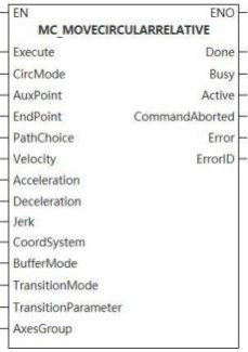
Device used (Only a single device can be used, and device splicing and index are not supported)
| Instruction | Parameter | Devices | Index modification | Pulse expansion | |||||||||||||||||||||||
|---|---|---|---|---|---|---|---|---|---|---|---|---|---|---|---|---|---|---|---|---|---|---|---|---|---|---|---|
| X | Y | M | S | SM | T(bit) | C(bit) | LC(bit) | HSC(bit) | D.b | KnX | KnY | KnM | KnS | T | C | D | R | SD | LC | HSC | K | H | E | [D] | XXP | ||
| MC_MOVECIRCULARRELATIVE | Execute | ● | ● | ● | ● | ● | |||||||||||||||||||||
| CircMode | |||||||||||||||||||||||||||
| AuxPoint | |||||||||||||||||||||||||||
| EndPoint | |||||||||||||||||||||||||||
| PathChoice | |||||||||||||||||||||||||||
| Velocity | |||||||||||||||||||||||||||
| Acceleration | |||||||||||||||||||||||||||
| Deceleration | |||||||||||||||||||||||||||
| Jerk | |||||||||||||||||||||||||||
| CoordSystem | |||||||||||||||||||||||||||
| BufferMode | |||||||||||||||||||||||||||
| TransitionMode | |||||||||||||||||||||||||||
| TransitionParameter | |||||||||||||||||||||||||||
| AxesGroup | |||||||||||||||||||||||||||
| Done | ● | ● | ● | ● | |||||||||||||||||||||||
| Busy | ● | ● | ● | ● | |||||||||||||||||||||||
| Active | ● | ● | ● | ● | |||||||||||||||||||||||
| InstructionAborted | ● | ● | ● | ● | |||||||||||||||||||||||
| Error | ● | ● | ● | ● | |||||||||||||||||||||||
| ErrorID | |||||||||||||||||||||||||||
Precautions for use of devices
▪LC and HSC are signed 32-bit data types;
▪T, C, D, R and SD are signed 16-bit data types;
Variable type used
| Instruction | Parameter | Variable type | Can it be empty | Range | Description |
|---|---|---|---|---|---|
| MC_MOVECIRCUlARRELATIVE | Execute | BOOL | No | TRUE/FALSE | Enable |
| CircMode | WORD | No | [0 to 2] | Please check [8.9.3 Arc mode description] for more details on arc construction mode. | |
| AuxPoint | LREAL array | No | - | Please check [8.9.3 Arc mode description] for more details on auxiliary point. | |
| EndPoint | LREAL array | No | - | Please check [8.9.3 Arc mode description] for more details on end point. | |
| PathChoice | WORD | No | [0 to 1] | Please check [8.9.3 Arc mode description] for more details on arc path selection. | |
| Velocity | LREAL | No | [0 to 999999999. 999999] | Velocity | |
| Acceleration | LREAL | No | [0 to 999999999. 999999] | Acceleration | |
| Deceleration | LREAL | No | [0 to 999999999. 999999] | Deceleration | |
| Jerk | LREAL | Yes | [0 to 999999999. 999999] | Jerk:is valid in S-curve only. | |
| CoordSystem | WORD | Yes | - | Coordinate system | |
| BufferMode | WORD | Yes | [0 to 1] | Please check [8.9.5 Mode selection description] for more details. | |
| TransitionMode | WORD | Yes | [0 to 2] | Please check [8.9.4 Transition mode description] for more details. | |
| TransitionParameter | LREAL | Yes | [0 to 999999999. 999999] | Please check [8.9.4 Transition mode description] for more details on transition parameter. | |
| AxesGroup | WORD | No | [0 to 65535] | Axis group number | |
| Done | BOOL | Yes | TRUE/FALSE | Completion flag | |
| Busy | BOOL | Yes | TRUE/FALSE | Busy flag | |
| Active | BOOL | Yes | TRUE/FALSE | Valid flag | |
| InstructionAborted | BOOL | Yes | TRUE/FALSE | Abortion flag | |
| Error | BOOL | Yes | TRUE/FALSE | Whether there is an error or not | |
| ErrorID | DWORD | Yes | - | Error code (Please check [8. 10 Error Code Cross-reference Table] ) |
Features
▪This function block executes circular interpolation motion, and puts the actual TCP position to the absolute position specified by a specific coordsystem.
Error code
| Error code | Content |
|---|---|
| 4084H | Input data beyond the specifiable range |

MC_MOVEDIRECTABSOLUTE
MC_MOVEDIRECTABSOLUTE
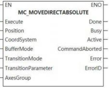
This function block is the fast positioning of absolute position.
Device used (Only a single device can be used, and device splicing and index are not supported)
| Instruction | Parameter | Devices | Index modification | Pulse expansion | |||||||||||||||||||||||
|---|---|---|---|---|---|---|---|---|---|---|---|---|---|---|---|---|---|---|---|---|---|---|---|---|---|---|---|
| X | Y | M | S | SM | T(bit) | C(bit) | LC(bit) | HSC(bit) | D.b | KnX | KnY | KnM | KnS | T | C | D | R | SD | LC | HSC | K | H | E | [D] | XXP | ||
| MC_MOVECIRCULARRELATIVE | Execute | ● | ● | ● | ● | ● | |||||||||||||||||||||
| Position | |||||||||||||||||||||||||||
| CoordSystem | |||||||||||||||||||||||||||
| BufferMode | |||||||||||||||||||||||||||
| TransitionMode | |||||||||||||||||||||||||||
| TransitionParameter | |||||||||||||||||||||||||||
| AxesGroup | |||||||||||||||||||||||||||
| Done | ● | ● | ● | ● | |||||||||||||||||||||||
| Busy | ● | ● | ● | ● | |||||||||||||||||||||||
| Active | ● | ● | ● | ● | |||||||||||||||||||||||
| InstructionAborted | ● | ● | ● | ● | |||||||||||||||||||||||
| Error | ● | ● | ● | ● | |||||||||||||||||||||||
| ErrorID | |||||||||||||||||||||||||||
Precautions for use of devices
▪LC and HSC are signed 32-bit data types;
▪T, C, D, R and SD are signed 16-bit data types;
Variable type used
| Instruction | Parameter | Variable type | Can it be empty | Range | Description |
|---|---|---|---|---|---|
| MC_MOVELINEARRELATIVE | Execute | BOOL | No | TRUE/FALSE | Enable |
| Position | LREAL array | No | - | Please check [8.9.3 Arc mode description] for more details on arc construction mode. | |
| CoordSystem | WORD | Yes | 0 | Coordinate system | |
| BufferMode | WORD | Yes | [0 to 1] | Please check [8.9.5 Mode selection description] for more details. | |
| TransitionMode | WORD | Yes | [0 to 2] | Please check [8.9.4 Transition mode description] for more details. | |
| TransitionParameter | LREAL | Yes | [0 to 999999999. 999999] | Please check [8.9.4 Transition mode description] for more details on transition parameter. | |
| AxesGroup | WORD | No | [0 to 65535] | Axis group number | |
| Done | BOOL | Yes | TRUE/FALSE | Completion flag | |
| Busy | BOOL | Yes | TRUE/FALSE | Busy flag | |
| Active | BOOL | Yes | TRUE/FALSE | Valid flag | |
| InstructionAborted | BOOL | Yes | TRUE/FALSE | Abortion flag | |
| Error | BOOL | Yes | TRUE/FALSE | Whether there is an error or not | |
| ErrorID | DWORD | Yes | - | Error code (Please check [8. 10 Error Code Cross-reference Table] ) |
Features
▪ The function block puts the axis group to the absolute position specified in the specific coordinate system, and does not emphasize on how to reach the target position;
▪The performance of each axis in the axis group, such as velocity, acceleration, deceleration, jerk, does not change when moving.
Error code
| Error code | Content |
|---|---|
| 4084H | Data beyond the specifiable range was input. |

MC_MOVEDIRECTRELATIVE
MC_MOVEDIRECTRELATIVE
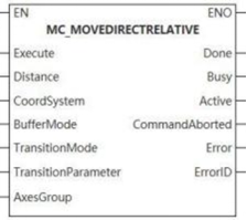
The function block executes the fast positioning of the relative position.
Device used (Only a single device can be used, and device splicing and index are not supported)
| Instruction | Parameter | Devices | Index modification | Pulse expansion | |||||||||||||||||||||||
|---|---|---|---|---|---|---|---|---|---|---|---|---|---|---|---|---|---|---|---|---|---|---|---|---|---|---|---|
| X | Y | M | S | SM | T(bit) | C(bit) | LC(bit) | HSC(bit) | D.b | KnX | KnY | KnM | KnS | T | C | D | R | SD | LC | HSC | K | H | E | [D] | XXP | ||
| MC_MOVEDIRECTRELATIVE | Execute | ● | ● | ● | ● | ● | |||||||||||||||||||||
| Distance | |||||||||||||||||||||||||||
| CoordSystem | |||||||||||||||||||||||||||
| BufferMode | |||||||||||||||||||||||||||
| TransitionMode | |||||||||||||||||||||||||||
| TransitionParameter | |||||||||||||||||||||||||||
| AxesGroup | |||||||||||||||||||||||||||
| Done | ● | ● | ● | ● | |||||||||||||||||||||||
| Busy | ● | ● | ● | ● | |||||||||||||||||||||||
| Active | ● | ● | ● | ● | |||||||||||||||||||||||
| InstructionAborted | ● | ● | ● | ● | |||||||||||||||||||||||
| Error | ● | ● | ● | ● | |||||||||||||||||||||||
| ErrorID | |||||||||||||||||||||||||||
Precautions for use of devices
▪LC and HSC are signed 32-bit data types;
▪T, C, D, R and SD are signed 16-bit data types;
Variable type used
| Instruction | Parameter | Variable type | Can it be empty | Range | Description |
|---|---|---|---|---|---|
| MC_MOVEDIRECTRELATIVE | Execute | BOOL | No | TRUE/FALSE | Enable |
| Distance | LREAL array | No | - | Please check [8.9.3 Arc mode description] for more details on arc construction mode. | |
| CoordSystem | WORD | Yes | 0 | Coordinate system | |
| BufferMode | WORD | Yes | [0 to1] | Please check [8.9.5 Mode selection description] for more details. | |
| TransitionMode | WORD | Yes | [0 to 2] | Please check [8.9.4 Transition mode description] for more details. | |
| TransitionParameter | LREAL | Yes | [0 to 999999999. 999999] | Please check [8.9.4 Transition mode description] for more details on transition parameter. | |
| AxesGroup | WORD | No | [0 to 65535] | Axis group number | |
| Done | BOOL | Yes | TRUE/FALSE | Completion flag | |
| Busy | BOOL | Yes | TRUE/FALSE | Busy flag | |
| Active | BOOL | Yes | TRUE/FALSE | Valid flag | |
| InstructionAborted | BOOL | Yes | TRUE/FALSE | Abortion flag | |
| Error | BOOL | Yes | TRUE/FALSE | Whether there is an error or not | |
| ErrorID | DWORD | Yes | - | Error code (Please check [8. 10 Error Code Cross-reference Table]) |
Features
▪ The function block puts the axis group to the relative position specified in the specific coordinate system, and does not emphasize on how to reach the target position;
▪The performance of each axis in the axis group, such as velocity, acceleration, deceleration, jerk, does not change when moving.
Error code
| Error code | Content |
|---|---|
| 4084H | Input data beyond the specifiable range |

Other special FB
MC_MOVEJOG
MC_MOVEJOG
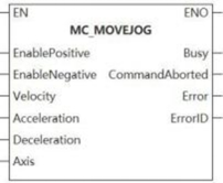
The function block makes the controlled axis execute micro motion at the set target velocity.
Device used (Only a single device can be used, and device splicing and index are not supported)
| Instruction | Parameter | Devices | Index modification | Pulse expansion | |||||||||||||||||||||||
|---|---|---|---|---|---|---|---|---|---|---|---|---|---|---|---|---|---|---|---|---|---|---|---|---|---|---|---|
| X | Y | M | S | SM | T(bit) | C(bit) | LC(bit) | HSC(bit) | D.b | KnX | KnY | KnM | KnS | T | C | D | R | SD | LC | HSC | K | H | E | [D] | XXP | ||
| MC_MOVEJOG | EnablePositive | ● | ● | ● | ● | ● | |||||||||||||||||||||
| EnableNegative | ● | ● | ● | ● | ● | ||||||||||||||||||||||
| Velocity | |||||||||||||||||||||||||||
| Acceleration | |||||||||||||||||||||||||||
| Deceleration | |||||||||||||||||||||||||||
| Axis | |||||||||||||||||||||||||||
| Busy | ● | ● | ● | ● | |||||||||||||||||||||||
| InstructionAborted | ● | ● | ● | ● | |||||||||||||||||||||||
| Error | ● | ● | ● | ● | |||||||||||||||||||||||
| ErrorID | |||||||||||||||||||||||||||
Precautions for use of devices
▪LC and HSC are signed 32-bit data types;
▪T, C, D, R and SD are signed 16-bit data types;
Variable type used
| Instruction | Parameter | Variable type | Can it be empty | Range | Description |
|---|---|---|---|---|---|
| MC_MOVEJOG | EnablePositive | BOOL | No | TRUE/FALSE | Positive motion |
| EnableNegative | BOOL | No | TRUE/FALSE | Negative motion | |
| Velocity | LREAL | No | [0 to 999999999. 999999] | Velocity | |
| Acceleration | LREAL | No | [0 to 999999999. 999999] | Acceleration | |
| Deceleration | LREAL | No | [0 to 999999999. 999999] | Deceleration | |
| Axis | WORD, AXIS_INFO_T | No | [0 to 65535] | Axis number | |
| Busy | BOOL | Yes | TRUE/FALSE | Busy flag | |
| InstructionAborted | BOOL | Yes | TRUE/FALSE | Abortion flag | |
| Error | BOOL | Yes | TRUE/FALSE | Whether there is an error or not | |
| ErrorID | DWORD | Yes | - | Error code (Please check [8. 10 Error Code Cross-reference Table] ) |
Features
▪When input Enablepositive signal on the rising edge, the controlled axis executes positive motion according to the input velocity.
▪When input EnableNegative signal on the rising edge, the controlled axis executes negative motion according to the input velocity.
▪In the process of positive motion, modifying the Enablepositive to FALSE causes deceleration until the axis stops. In the process of deceleration, if Enablepositive is changed to TRUE, the axis will continue to move until reaching the specified velocity. In the process of deceleration, if EnableNegative is changed to TRUE, the axis will decrease its velocity to 0 and then execute negative motion until its velocity reaches the specified velocity.
Error code
| Error code | Content |
|---|---|
| 4084H | Input data beyond the specifiable range |
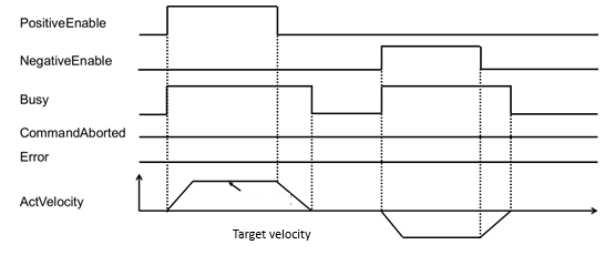
MC_COMBINEAXES
MC_COMBINEAXES
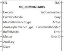
The function block adds and subtracts the positions of the master axis and the auxiliary axis as the position of the slave axis.
Device used (Only a single device can be used, and device splicing and index are not supported)
| Instruction | Parameter | Devices | Index modification | Pulse expansion | |||||||||||||||||||||||
|---|---|---|---|---|---|---|---|---|---|---|---|---|---|---|---|---|---|---|---|---|---|---|---|---|---|---|---|
| X | Y | M | S | SM | T(bit) | C(bit) | LC(bit) | HSC(bit) | D.b | KnX | KnY | KnM | KnS | T | C | D | R | SD | LC | HSC | K | H | E | [D] | XXP | ||
| MC_COMBINEAXES | Execute | ● | ● | ● | ● | ● | |||||||||||||||||||||
| ConbineMode | |||||||||||||||||||||||||||
| MasterReferenceType | |||||||||||||||||||||||||||
| AuxiliaryReferenceType | |||||||||||||||||||||||||||
| BufferMode | |||||||||||||||||||||||||||
| Master | |||||||||||||||||||||||||||
| Auxiliary | |||||||||||||||||||||||||||
| Slave | |||||||||||||||||||||||||||
| InCombiantion | ● | ● | ● | ● | |||||||||||||||||||||||
| Busy | ● | ● | ● | ● | |||||||||||||||||||||||
| Active | ● | ● | ● | ● | |||||||||||||||||||||||
| InstructionAborted | ● | ● | ● | ● | |||||||||||||||||||||||
| Error | ● | ● | ● | ● | |||||||||||||||||||||||
| ErrorID | |||||||||||||||||||||||||||
Precautions for use of devices
▪LC and HSC are signed 32-bit data types;
▪T, C, D, R and SD are signed 16-bit data types;
Variable type used
| Instruction | Parameter | Variable type | Can it be empty | Range | Description |
|---|---|---|---|---|---|
| MC_COMBINEAXES | Execute | BOOL | No | TRUE/FALSE | Enable |
| ConbineMode | WORD | Yes | [0 to 1] | Addition and subtraction operation selection 0: Addition 1: Subtraction | |
| MasterReferenceType | WORD | Yes | [1 to 2] | Master axis position type 1: Feedback position 2: Instruction position | |
| AuxiliaryReferenceType | WORD | Yes | [1 to 2] | Auxiliary axis position type 1: Feedback position 2: Instruction position | |
| BufferMode | LREAL | No | 0 | Mode selection | |
| Master | WORD, AXIS INFO T | No | [0 to 65535] | Master axis number | |
| Auxiliary | WORD, AXIS INFO T | No | [0 to 65535] | Auxiliary axis number | |
| Slave | WORD, AXIS INFO T | No | [0 to 65535] | Slave axis number | |
| InCombiantion | BOOL | Yes | TRUE/FALSE | Addition and subtraction operation flag | |
| Busy | BOOL | Yes | TRUE/FALSE | Busy flag | |
| Active | BOOL | Yes | TRUE/FALSE | Valid flag | |
| InstructionAborted | BOOL | Yes | TRUE/FALSE | Abortion flag | |
| Error | BOOL | Yes | TRUE/FALSE | Whether there is an error or not | |
| ErrorID | DWORD | Yes | - | Error code (Please check [8. 10 Error Code Cross-reference Table] ) |
Features
▪On the Execute rising edge, the addition and subtraction positioning operation is performed.
Error code
| Error code | Content |
|---|---|
| 7000OA | Axis is in a bound status. |
| 7000OB | Axis cannot be bound at run time. |
| 800014 | The master axis is consistent with the slave axis. |
| 800015 | The master axis is consistent with the auxiliary axis. |
| 800016 | The auxiliary axis is consistent with the slave axis. |
| 800017 | Master axis (auxiliary axis) and slave axis numbers are not ascending order. |
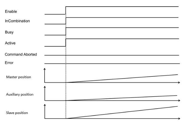
MC_MOVEVELOCITY
MC_MOVEVELOCITY
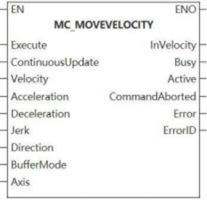
Device used (Only a single device can be used, and device splicing and index are not supported)
| Instruction | Parameter | Devices | Index modification | Pulse expansion | |||||||||||||||||||||||
|---|---|---|---|---|---|---|---|---|---|---|---|---|---|---|---|---|---|---|---|---|---|---|---|---|---|---|---|
| X | Y | M | S | SM | T(bit) | C(bit) | LC(bit) | HSC(bit) | D.b | KnX | KnY | KnM | KnS | T | C | D | R | SD | LC | HSC | K | H | E | [D] | XXP | ||
| MC_MOVEVELOCITY | Execute | ● | ● | ● | ● | ● | |||||||||||||||||||||
| ContinuousUpdate | ● | ● | ● | ● | ● | ||||||||||||||||||||||
| Velocity | |||||||||||||||||||||||||||
| Acceleration | |||||||||||||||||||||||||||
| Deceleration | |||||||||||||||||||||||||||
| Jerk | |||||||||||||||||||||||||||
| Direction | |||||||||||||||||||||||||||
| BufferMode | |||||||||||||||||||||||||||
| Axis | |||||||||||||||||||||||||||
| InVelocity | ● | ● | ● | ● | |||||||||||||||||||||||
| Busy | ● | ● | ● | ● | |||||||||||||||||||||||
| Active | ● | ● | ● | ● | |||||||||||||||||||||||
| InstructionAborted | ● | ● | ● | ● | |||||||||||||||||||||||
| Error | ● | ● | ● | ● | |||||||||||||||||||||||
| ErrorID | |||||||||||||||||||||||||||
Precautions for use of devices
▪LC and HSC are signed 32-bit data types;
▪T, C, D, R and SD are signed 16-bit data types;
Variable type used
| Instruction | Parameter | Variable type | Can it be empty | Range | Description |
|---|---|---|---|---|---|
| MC_MOVEVELOCITY | Execute | BOOL | No | TRUE/FALSE | Enable |
| ContinuousUpdate | BOOL | No | TRUE/FALSE | Reserve | |
| Velocity | LREAL | No | [0 to 999999999. 999999] | The set velocity | |
| Acceleration | LREAL | No | [0 to 999999999. 999999] | The set acceleration | |
| Deceleration | LREAL | No | [0 to 999999999. 999999] | The set deceleration | |
| Jerk | LREAL | Yes | [0 to 999999999. 999999] | The set jerk is only valid in the S-curve. | |
| Direction | WORD | No | [1] | Direction flag 1: Positive direction 2: Negative direction 3: Current direction 4: Shortest path | |
| BufferMode | WORD | Yes | [0] | Buffer mode | |
| Axis | WORD, AXIS INFO T | No | [0 to 65535] | Axis number and axis in-built variable | |
| InVelocity | BOOL | Yes | TRUE/FALSE | Reach the set velocity flag | |
| Busy | BOOL | Yes | TRUE/FALSE | Busy flag | |
| Active | BOOL | Yes | TRUE/FALSE | Valid flag | |
| InstructionAborted | BOOL | Yes | TRUE/FALSE | Abortion flag | |
| Error | BOOL | Yes | TRUE/FALSE | Whether there is an error or not | |
| ErrorID | DWORD | Yes | - | Error code (Please check [8. 10 Error Code Cross-reference Table] ) |
Features
▪MC_MOVEVELOCITY function block is used for continuing the motion of the previous function block and moving according to the velocity specified by the previous function block. The input values of acceleration, deceleration and jerk are used to monitor whether the corresponding values of the controlled axis are within the input values.
▪Since there is no input signal of position or distance, the function block will move until other function block sends a new command to stop the operation of this function block;
▪When the velocity of the controlled axis reaches the set value of input parameter Velocity, the output parameter Invelocity is set to ON.
▪Once the input Execute signal detects that the falling edge or other function block makes this function block abort, the output parameter Invelocity is reset.
▪MC_MOVEVELOCITY function block should be used when the controlled axis is in a stop status or a single-axis running status. When the function block is triggered, the controlled axis is switched to continuous Motion status.
▪If the controlled axis is not in the above status, the function block is not executed. Erroroutput is set;
▪MC_MOVEVELOCITY function block can be triggered repeatedly.
Error code
| Error code | Content |
|---|---|
| 4084H | Input data beyond the specifiable range |
MC _ MOVEVELOCITY _ CSV
MC _ MOVEVELOCITY _ CSV-Sets motion according to the speed specified by the function block
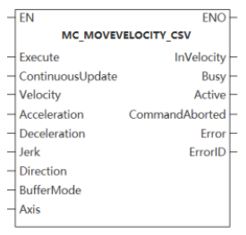
The function block is used to continue the motion of the previous function block and move according to the speed specified by the function block.
Device used (only a single device can be used, device splicing and index are not supported)
| Instruction | Parameter | Device | Index Modification | Pulse Expansion | |||||||||||||||||||||||
| X | Y | M | S | SM | T(bit) | C(bit) | LC(bit) | HSC(bit) | D.b | KnX | KnY | KnM | KnS | T | C | D | R | SD | LC | HSC | K | H | E | [D] | XXP | ||
MC _ MOVEVELOCITY _ CSV | Execute | ● | ● | ● | ● | ● | |||||||||||||||||||||
| ContinuousUpdate | ● | ● | ● | ● | ● | ||||||||||||||||||||||
| Velocity | |||||||||||||||||||||||||||
| Acceleration | |||||||||||||||||||||||||||
| Deceleration | |||||||||||||||||||||||||||
| Jerk | |||||||||||||||||||||||||||
| Direction | |||||||||||||||||||||||||||
| BufferMode | |||||||||||||||||||||||||||
| Axis | |||||||||||||||||||||||||||
| InVelocity | ● | ● | ● | ● | |||||||||||||||||||||||
| Busy | ● | ● | ● | ● | |||||||||||||||||||||||
| Active | ● | ● | ● | ● | |||||||||||||||||||||||
| CommandAborted | ● | ● | ● | ● | |||||||||||||||||||||||
| Error | ● | ● | ● | ● | |||||||||||||||||||||||
| Error ID | |||||||||||||||||||||||||||
Notes:
- LC and HSC are signed 32-bit data types;
- T, C, D, R and SD are signed 16-bit data types.
Variable type used
| Instruction | Parameter | Variable type | Can it be empty | Range | Description |
MC _ MOVE VELOCITY _ CSV | Execute | BOOL | No | TRUE/FALSE | Enable |
| ContinuousUpdate | BOOL | Yes | TRUE/FALSE | Whether update continuously or not | |
| Velocity | LREAL | No | [0,999999999.999999] | Setting velocity | |
| Acceleration | LREAL | No | [0,999999999.999999] | Setting acceleration | |
| Deceleration | LREAL | No | [0,999999999.999999] | Set deceleration | |
| Jerk | LREAL | Yes | [0,999999999.999999] | The set jerk is only effective in S-curve. | |
| Direction | WORD | No | [1,4] | Direction flag bit (Only rotation mode takes effect)。 1. Positive direction; 2. Negative direction; 3. The current direction; 4. The shortest path (reserved). | |
| BufferMode | WORD | Yes | [0] | BufferMode | |
| Axis | WORD | No | [0,65535] | Axis number and built-in variable of axis | |
| InVelocity | BOOL | Yes | TRUE/FALSE | Reach the set velocity flag bit | |
| Busy | BOOL | Yes | TRUE/FALSE | Busy flag | |
| Active | BOOL | Yes | TRUE/FALSE | Activity flag | |
| Command aborted | BOOL | Yes | TRUE/FALSE | Interrupt flag bit | |
| Error | BOOL | Yes | TRUE/FALSE | Whether there is an error or not | |
| Error ID | DWORD | Yes | - | Error code (Please refer to [8.11 Error code comparison table]) |
Function
- The MC _ MoveVelocity function block is used to continue the movement of the previous function block and move according to the speed specified by the function block. The input values of acceleration, deceleration and jerk are used to monitor whether the corresponding values of the controlled axis are within the input values.
- Since there is no input signal of position or distance, the function block will move until other function block sends a new command to stop movement of this function block;
- When the speed of the controlled axis reaches the input parameter ‘Velocity’ setpoint, the output parameter ‘InVelocity’ is set. Once the input ‘Execute’ signal detects a falling edge or other function block to abort this function block, the output parameter InVelocity is reset;
- The MC _ MoveVelocity function block shall be in a stopped motion state or a single-axis operation state when the controlled axis is operated. After this function block is triggered, the controlled axis transitions to the ‘Continuous Motion’ state. If the controlled axis is not in the above state, the function block is not executed, Error output is set;
- The MC _ MoveVelocity function block can be triggered repeatedly multiple times.
Error code
| Error code | Content |
| 4084H | Input data beyond the specifiable range |
Precautions
- Different from the MC _ MOVEVELOCITY function block, this function block will automatically switch the servo mode to CSV (Synchronous Cycle Speed) mode;
- Using this function block requires adding four object dictionaries, H60FF, H6060, H6061, and H606C, to the PDO.
Timing diagram

MC _ SYNCMOVEVELOCITY
MC _ SYNCMOVEVELOCITY-Sets motion according to the speed specified by the function block
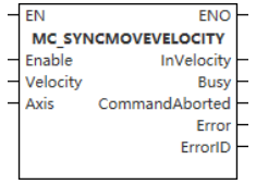
The function block is used to continue the motion of the previous function block and move according to the speed specified by the function block.
Device used (only a single device can be used, and device splicing and Index are not supported)
| Instruction | Parameter | Device | Index modification | Pulse expansion | |||||||||||||||||||||||
| X | Y | M | S | SM | T(bit) | C(bit) | LC(bit) | HSC(bit) | D.b | KnX | KnY | KnM | KnS | T | C | D | R | SD | LC | HSC | K | H | E | [D] | XXP | ||
MC _ SYNCMOVE VELOCITY | Execute | ● | ● | ● | ● | ● | |||||||||||||||||||||
| Velocity | |||||||||||||||||||||||||||
| Axis | |||||||||||||||||||||||||||
| InVelocity | ● | ● | ● | ● | |||||||||||||||||||||||
| Busy | ● | ● | ● | ● | |||||||||||||||||||||||
| CommandAborted | ● | ● | ● | ● | |||||||||||||||||||||||
| Error | ● | ● | ● | ● | |||||||||||||||||||||||
| ErrorID | |||||||||||||||||||||||||||
Notes for using devices
- LC and HSC are signed 32-bit data types;
- T, C, D, R and SD are signed 16-bit data types.
Variable type used
| Instruction | Parameter | Variable type | Empty or not | Range | Description |
MC _ SYNCMOVE VELOCITY | Execute | BOOL | No | TRUE/FALSE | Enable |
| Velocity | LREAL | No | [0,999999999.999999] | Setting velocity | |
| Axis | WORD
| No | [0,65535] | Axis number and built-in variable of axis | |
| InVelocity | BOOL | Yes | TRUE/FALSE | Reach the set velocity flag bit | |
| Busy | BOOL | Yes | TRUE/FALSE | Busy flag | |
| CommandAborted | BOOL | Yes | TRUE/FALSE | Interrupt flag bit | |
| Error | BOOL | Yes | TRUE/FALSE | Whether there is an error or not | |
| ErrorID | DWORD | Yes | - | Error code (Please refer to |
Function
- The MC _ SYNCMOVEVELOCITY function block function block is used to continue the movement of the previous function block and move according to the speed specified by the function block.
- Since there is no input signal of position or distance, the function block will move until other function block sends a new command to stop movement of this function block;
- When the speed of the controlled axis reaches the input parameter Velocity setpoint, the output parameter InVelocity is set. Once the input ‘Execute’ signal detects a falling edge or other function block to abort this function block, the output parameter ‘InVelocity’ is reset;
- The MC _ SYNCMOVEVELOCITY function block shall be in a stopped motion state or a single-axis operation state when the controlled axis is operated. After this function block is triggered, the controlled axis transitions to the ‘Continuous Motion’ state. If the controlled axis is not in the above state, the function block is not executed, Error output is set;
- The MC _ SYNCMOVEVELOCITY function block can be triggered repeatedly multiple times.
✎Note: After using MC _ SYNCMOVEVELOCITY , the servo mode is automatically switched to the synchronous cycle speed mode.
Error code
| Error code | Content |
| 4084H | Input data beyond the specifiable range |
Timing diagram
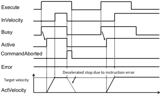
MC _ SETTORQUE
MC _ SETTORQUE-Synchronous torque instruction
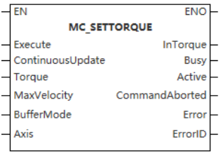
Device used (only a single device can be used, and device splicing and Index are not supported)
| Instruction | Parameter | Device | Index Modification | Pulse Expansion | |||||||||||||||||||||||
| X | Y | M | S | SM | T(bit) | C(bit) | LC(bit) | HSC(bit) | D.b | KnX | KnY | KnM | KnS | T | C | D | R | SD | LC | HSC | K | H | E | [D] | XXP | ||
| MC _ SETTORQUE | Execute | ● | ● | ● | ● | ● | |||||||||||||||||||||
| TORQUE | |||||||||||||||||||||||||||
| MaxVelocity | |||||||||||||||||||||||||||
| BufferMode | |||||||||||||||||||||||||||
| Axis | |||||||||||||||||||||||||||
| InTorque | ● | ● | ● | ● | |||||||||||||||||||||||
| Busy | ● | ● | ● | ● | |||||||||||||||||||||||
| Active | ● | ● | ● | ● | |||||||||||||||||||||||
| CommandAborted | ● | ● | ● | ● | |||||||||||||||||||||||
| Error | ● | ● | ● | ● | |||||||||||||||||||||||
| ErrorID | |||||||||||||||||||||||||||
Notes for using devices
- LC and HSC are signed 32-bit data types;
- T, C, D, R and SD are signed 16-bit data types.
Variable type used
| Instruction | Pin Type | Parameter | Variable type | Empty or not | Range | Description |
| MC _ SETTORQUE | Input | Execute | BOOL | No | TRUE/FALSE | Enable |
| ContinuousUpdate | BOOL | Yes | TRUE/FALSE | Updated during operation | ||
| Torque | LREAL | No | [-32768,32767] | Target torque (unit is 0.1%) | ||
| MaxVelocity | LREAL | No | [0,999999999.999999] | Maximum speed | ||
| BufferMode | WORD | Yes | [0] | Currently only interrupts are supported | ||
| Axis | WORD | No | [0,65535] | Axis number | ||
| Output | InTorque | BOOL | Yes | TRUE/FALSE | Completion flag | |
| Busy | BOOL | Yes | TRUE/FALSE | Busy flag | ||
| Active | BOOL | Yes | TRUE/FALSE | Valid flag | ||
| CommandAborted | BOOL | Yes | TRUE/FALSE | Abortion flag | ||
| Error | BOOL | Yes | TRUE/FALSE | Error or not | ||
| ErrorID | DWORD | Yes | - | Error code ( Please refer to [8.11 Error code comparison table]) |
Function
- This instruction is used to implement the synchronous torque control function and is only used for the bus servo axis. The rising edge and high level of the command are valid, and the virtual axis mode is not supported.
- The following PDOs need to be configured in CST mode;
0x1600: 0x6060, 0x6071, 607f (optional), 6040
0x1A00: 0x6061, 0x6077, 0x6041
- If you use VD3E, you need to configure the startup parameter 2001: 9 value to 2;
- When Enable = ON, the function block converts TarTorque and MaxVelocity from user units to pulse units and sends them to the servo driver from time to time. The shaft is in the Continuous Motion state and performs synchronous torque motion. When the falling edge of Eanble, the function block performs synchronous torque motion with the TarTorque and Velocity latched during the high level, and it is invalid to modify the TarTorque and Velocity in real time;
- This instruction can only be invoked if the axis is switched to the enabled state using the MC _ Power instruction;
- This instruction uses the driver synchronous torque mode to realize the torque control function. When Enable = ON, the function block converts TarTorque and Velocity from user units to pulse units and sends them to the servo driver from time to time. The shaft is in the Continuous Motion state and performs synchronous torque motion;
TarTorque: The target torque, the unit is 0.1%. One decimal place after the decimal point is valid in the program, and the latter ones are directly discarded. The actual torque of the driver is limited by the maximum positive and negative torques set in the configuration parameters.
Note
- This function block is not available when the axis does not exist.
MC _ TORQUECONTROL
MC _ TORQUECONTROL-Torque control command

Device used (only a single device can be used, and device splicing and Index are not supported)
| Instruction | Parameter | Device | Index Modification | Pulse Expansion | |||||||||||||||||||||||
| X | Y | M | S | SM | T(bit) | C(bit) | LC(bit) | HSC(bit) | D.b | KnX | KnY | KnM | KnS | T | C | D | R | SD | LC | HSC | K | H | E | [D] | XXP | ||
MC _ TORQUE CONTROL | Execute | ● | ● | ● | ● | ● | |||||||||||||||||||||
| ContinuousUpdate | ● | ● | ● | ● | ● | ||||||||||||||||||||||
| TORQUE | |||||||||||||||||||||||||||
| TorqueRamp | |||||||||||||||||||||||||||
| MaxVelocity | |||||||||||||||||||||||||||
| BufferMode | |||||||||||||||||||||||||||
| Axis | |||||||||||||||||||||||||||
| InTorque | ● | ● | ● | ● | |||||||||||||||||||||||
| Busy | ● | ● | ● | ● | |||||||||||||||||||||||
| Active | ● | ● | ● | ● | |||||||||||||||||||||||
| CommandAborted | ● | ● | ● | ● | |||||||||||||||||||||||
| Error | ● | ● | ● | ● | |||||||||||||||||||||||
| ErrorID | |||||||||||||||||||||||||||
Notes for using devices
- LC and HSC are signed 32-bit data types;
- T, C, D, R and SD are signed 16-bit data types.
Variable type used
| Instruction | Pin Type | Parameter | Variable type | Empty or not | Range | Description |
| MC _ TORQUECONTROL | Input | Execute | BOOL | No | TRUE/FALSE | Enable |
| ContinuousUpdate | BOOL | Yes | TRUE/FALSE | Updated during operation | ||
| Torque | LREAL | No | [-32768,32767] | Target torque (unit is 0.1%) | ||
| MaxVelocity | LREAL | No | [0,999999999.999999] | Maximum speed | ||
| TorqueRamp | LREAL | No | [0,999999999.999999] | Torque slope | ||
| BufferMode | WORD | Yes | [0] | Only interrupt mode supported | ||
| Axis | WORD | No | [0,65535] | Axis number | ||
| Output | InTorque | BOOL | Yes | TRUE/FALSE | Completion flag | |
| Busy | BOOL | Yes | TRUE/FALSE | Busy flag | ||
| Active | BOOL | Yes | TRUE/FALSE | Valid flag | ||
| CommandAborted | BOOL | Yes | TRUE/FALSE | Abortion flag | ||
| Error | BOOL | Yes | TRUE/FALSE | Error or not | ||
| ErrorID | DWORD | Yes | - | Error code (Please refer to [8.11 Error code comparison table]) |
Function
- This instruction is used to realize the torque control function and is only used for the EtherCAT bus axis. The rising edge of the instruction is valid, and the imaginary axis mode is not supported.
- The following PDOs need to be configured in CST mode:
0x1600: 0x6060, 0x6071, 607f (optional), 6040
0x1A00: 0x6061, 0x6077, 0x6041
- If VD3E is used, the value of startup parameter 2001:9 is 2;
Function description
- This instruction can only be invoked if the axis is switched to the enabled state using the MC _ Power instruction;
- This instruction uses the driver synchronous torque mode to realize the torque control function;
- On the rising edge of the instruction, the function block latches the input parameters of TarTorque, TorqueSlope and MaxVelocity, and the axis is in the ContinuousMotion state and performs torque motion;
TarTorque: Target torque, the unit is 0.1%, one decimal place after the decimal point is valid in the program, and the latter ones are discarded. The actual torque of the driver is limited by the maximum positive and negative torques set in the configuration parameters;
TorqueSlope: Moment slope, the unit is 1%, one decimal place after the decimal point is valid in the program, and the latter ones are directly discarded;
- Speed control in torque mode
For servo drives, if 0x607f is mapped in the axis parameter, this instruction limits the maximum speed of the servo motor by 0x607f, if 0x607f is not mapped, the speed limit is invalid;
On the rising edge of Execute, the instruction converts the speed limit set by Velocity into pulse units and writes it into 0x607f through PDO;
When the torque instruction is interrupted by others, the maximum speed of the axis will be limited by the "Maximum speed" in the configuration interface;
For third-party drives, Velocity can only be used as a speed limit under the following conditions:
The maximum speed of the servomotor can be limited by 0x607F;
0x607F can be configured into the PDO;
The unit of 0x607F is pulse unit, non-speed unit.
- Stop control on torque mode
In the torque mode, the MC _ Stop instruction is called to perform the shut down, and after receiving the Stop instruction, the driver switches to the synchronous position mode, and performs deceleration according to the deceleration set by the Stop instruction.
- Interrupt
In PLCOpen, when the instruction is valid, the axis will be in the Continuous Motion state. Other instructions that can make the axis in Discrete motion or comply with PLCOpen state machine switching can interrupt the instruction. When the instruction is interrupted, CommandAboarted is valid;
CommandAboarted is valid when Execute=ON and Done signal is invalid and is about to hit the limit signal execution needs to perform deceleration;
The axis de-enable CommandAboarted is valid when Execute=ON and the Done signal is invalid.
Timing diagram
After setting the target torque, the command is triggered, and the actual output torque can reach the target torque.
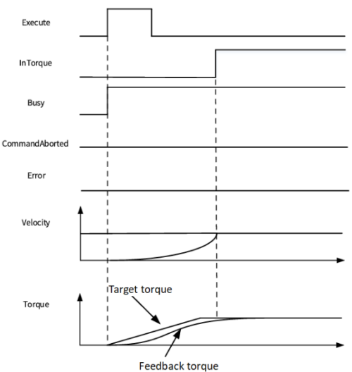
After setting the target torque, the command is triggered, and finally the actual output torque cannot reach the target torque.
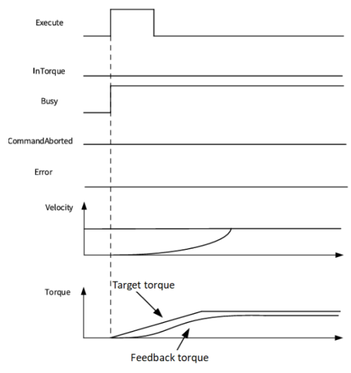
MC _ MOVEABSRELPP
MC _ MOVEABSRELPP-Positioning instruction based on contour position mode
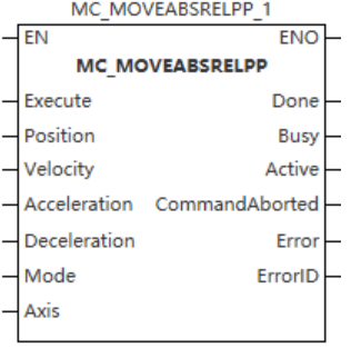
Device used (only a single device can be used, and device splicing and Index are not supported)
| Instruction | Parameter | Device | Index modification | Pulse Expansion | |||||||||||||||||||||||
| X | Y | M | S | SM | T(bit) | C(bit) | LC(bit) | HSC(bit) | D.b | KnX | KnY | KnM | KnS | T | C | D | R | SD | LC | HSC | K | H | E | [D] | XXP | ||
MC _ MOVEA BSRELPP | Execute | ● | ● | ● | ● | ● | |||||||||||||||||||||
| Position | |||||||||||||||||||||||||||
| Velocity | |||||||||||||||||||||||||||
| Acceleration | |||||||||||||||||||||||||||
| Deceleration | |||||||||||||||||||||||||||
| Mode | |||||||||||||||||||||||||||
| Axis | |||||||||||||||||||||||||||
| Done | ● | ● | ● | ● | |||||||||||||||||||||||
| Busy | ● | ● | ● | ● | |||||||||||||||||||||||
| Active | ● | ● | ● | ● | |||||||||||||||||||||||
| CommandAborted | ● | ● | ● | ● | |||||||||||||||||||||||
| Error | ● | ● | ● | ● | |||||||||||||||||||||||
| ErrorID | |||||||||||||||||||||||||||
Notes for using devices
- LC and HSC are signed 32-bit data types;
- T, C, D, R and SD are signed 16-bit data types.
Variable type used
| Instruction | Pin Type | Parameter | Variable type | Empty or not | Range | Description |
MC _ MOVE ABSRELPP | Input | Execute | BOOL | No | TRUE/FALSE | Enable |
| Mode | INT | No | 0,1 | 1: Absolute mode. 1: Relative mode | ||
| Position | LREAL | No | -999999999.999999 999999999.999999 | Target location | ||
| Velocity | LREAL | No | (0,999999999.999999] | Velocity | ||
| Acceleration | LREAL | No | (0,999999999.999999] | Acceleration | ||
| Deceleration | LREAL | No | (0,999999999.999999] | Deceleration | ||
| Axis | WORD | No | [0,65535] | Axis number | ||
| Output | Done | BOOL | Yes | TRUE/FALSE | Completion flag | |
| Busy | BOOL | Yes | TRUE/FALSE | Busy flag | ||
| Active | BOOL | Yes | TRUE/FALSE | Valid flag | ||
| CommandAborted | BOOL | Yes | TRUE/FALSE | Abortion flag | ||
| Error | BOOL | Yes | TRUE/FALSE | Error or not | ||
| ErrorID | DWORD | Yes | - | Error code (Please refer to [8.11 Error code comparison table]) |
Function
- This command is used to control the EtherCAT bus contour axis to realize the absolute/relative positioning function in contour position mode. In the basic settings of axis configuration, the contour mode option needs to be checked before it can be called, and the rising edge is valid.
- Contour Position Mode requires the following PDOs:
0x1600: 0x6081, 0x6083, 0x6084, 0x607A, 0x6060, 0x6040
0x1A00: 0x6061, 0x6064, 0x6041
Function description
- This instruction can only be invoked if the axis is switched to the enabled state using the MC _ Power instruction;
- At the rising edge of the Execute input, the instruction latches the input parameters on the left side such as Position and Velocity, triggers the absolute/relative positioning function, and switches the PLCOpen state machine of the axis to the DiscreteMotion state;
- When Mode = 0, the positioning Mode is absolute positioning Mode, and Position is used to set the target Position of absolute positioning. If the axis Mode is configured as rotation Mode, the target Position is positioned according to the shortest distance;
- When Mode = 1, the positioning Mode is a relative positioning Mode, and Position is used to set the target distance of relative positioning;
- Interrupt
When this instruction is valid in PLCOpen, the axis will be in the Discretemotion state. Other outline mode instructions that can make the axis in Discretemotion or comply with PLCOpen state machine switching can interrupt this instruction. CommandAboarted is valid when the instruction is interrupted. The instruction of periodic synchronization mode cannot be called, otherwise a fault will be reported;
CommandAboarted is valid when the MC _ Power instruction is invalid when Execute = TRUE and the Busy signal is valid causes the axis to be de-enabled.
Timing diagram
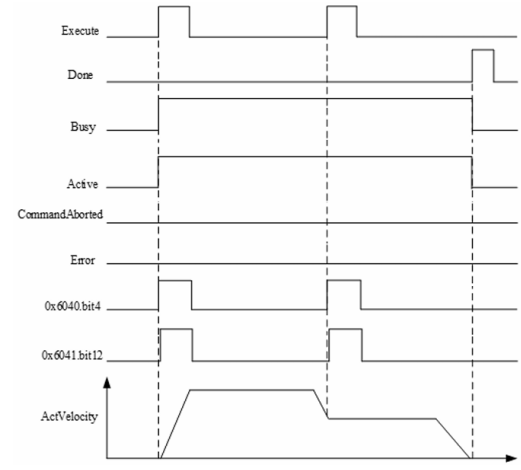
MC _ MOVEVELOCITYPV
MC _ MOVEVELOCITYPV-Contour Speed Command
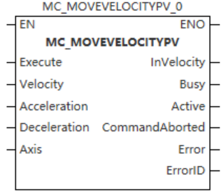
Device used (only a single device can be used, and device splicing and Index are not supported)
| Instruction | Parameter | Device | Index Modification | Pulse Expansion | |||||||||||||||||||||||
| X | Y | M | S | SM | T(bit) | C(bit) | LC(bit) | HSC(bit) | D.b | KnX | KnY | KnM | KnS | T | C | D | R | SD | LC | HSC | K | H | E | [D] | XXP | ||
MC _ MOVEVELO CITYPV | Execute | ● | ● | ● | ● | ● | |||||||||||||||||||||
| Velocity | |||||||||||||||||||||||||||
| Acceleration | |||||||||||||||||||||||||||
| Deceleration | |||||||||||||||||||||||||||
| Axis | |||||||||||||||||||||||||||
| InVelocity | ● | ● | ● | ● | |||||||||||||||||||||||
| Busy | ● | ● | ● | ● | |||||||||||||||||||||||
| Active | ● | ● | ● | ● | |||||||||||||||||||||||
| CommandAborted | ● | ● | ● | ● | |||||||||||||||||||||||
| Error | ● | ● | ● | ● | |||||||||||||||||||||||
| ErrorID | |||||||||||||||||||||||||||
Notes for using devices
- LC and HSC are signed 32-bit data types;
- T, C, D, R and SD are signed 16-bit data types.
Variable type used
| Instruction | Pin type | Parameter | Variable Type | Can you Is empty | Range | Description |
MC _ MOVEVE LOCITYPV | Input | Execute | BOOL | No | TRUE/FALSE | Enable |
| Velocity | LREAL | No | -999999999.999999 999999999.999999 | Velocity | ||
| Acceleration | LREAL | No | (0,999999999.999999] | Acceleration | ||
| Deceleration | LREAL | No | The QPS Exceeds Maximum Limit 5 | Deceleration | ||
| Axis | WORD | No | [0,65535] | Axis number | ||
| Output | InVelocity | BOOL | Yes | TRUE/FALSE | Completion flag | |
| Busy | BOOL | Yes | TRUE/FALSE | Busy flag | ||
| Active | BOOL | Yes | TRUE/FALSE | Valid flag | ||
| CommandAborted | BOOL | Yes | TRUE/FALSE | Abortion flag | ||
| Error | BOOL | Yes | TRUE/FALSE | Error or not | ||
| ErrorID | DWORD | Yes | - | Error code (Please refer to [8.11 Error code comparison table]) |
Function
- This command is used to realize the continuous motion function of EtherCAT bus contour axis in contour speed mode. In the basic settings of axis configuration, the contour mode option needs to be checked before it can be called, and the rising edge is valid;
- This instruction is a simulated velocity instruction based on the profile velocity (PV) mode;
- The following PDOs are required for the profile speed mode:
0x1600: 0x6083, 0x6084, 0x60FF, 0x6060, 0x6040
0x1A00: 0x6061, 0x606c, 0x6041
Function description
- This instruction can only be invoked if the axis is switched to the STANDSTILL state using the MC _ Power instruction;
- When Execute = TRUE, the instruction latches the input parameters on the left side such as Velocity and Acceleration, the axis continuously runs according to the target speed set by Velocity, and switches the PLCOpen state machine of the axis to the ContinuousMotion state.
Timing diagram
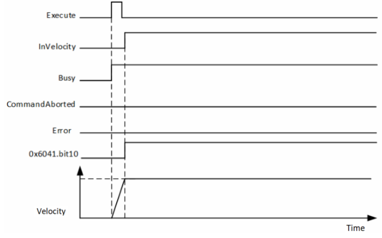
MC _ TORQUECONTROLPT
MC _ TORQUECONTROLPT-Contour torque control command
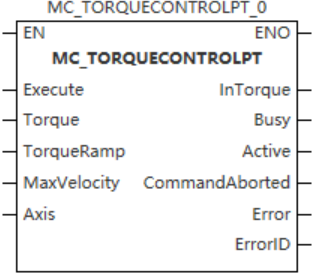
Device used (only a single device can be used, and device splicing and Index are not supported)
| Instruction | Parameter | Device | Index modification | Pulse expansion | |||||||||||||||||||||||
| X | Y | M | S | SM | T(bit) | C(bit) | LC(bit) | HSC(bit) | D.b | KnX | KnY | KnM | KnS | T | C | D | R | SD | LC | HSC | K | H | E | [D] | XXP | ||
MC _ TORQUE CONTROLPT | Execute | ● | ● | ● | ● | ● | |||||||||||||||||||||
| TORQUE | |||||||||||||||||||||||||||
| TorqueRamp | |||||||||||||||||||||||||||
| MaxVelocity | |||||||||||||||||||||||||||
| Axis | |||||||||||||||||||||||||||
| InTorque | ● | ● | ● | ● | |||||||||||||||||||||||
| Busy | ● | ● | ● | ● | |||||||||||||||||||||||
| Active | ● | ● | ● | ● | |||||||||||||||||||||||
| CommandAborted | ● | ● | ● | ● | |||||||||||||||||||||||
| Error | ● | ● | ● | ● | |||||||||||||||||||||||
| ErrorID | |||||||||||||||||||||||||||
Notes for using devices
- LC and HSC are signed 32-bit data types;
- T, C, D, R and SD are signed 16-bit data types.
Variable type used
| Instruction | Pin Type | Parameter | Variable type | Empty or not | Range | Description |
| MC_ TORQUECONTROLPT | Input | Execute | BOOL | No | TRUE/FALSE | Enable |
| Torque | LREAL | No | [-32768,32767] | Target torque (unit is 0.1%) | ||
| TorqueRamp | LREAL | No | (0,999999999.999999] | Torque slope | ||
| MaxVelocity | LREAL | No | [0,999999999.999999] | Maximum speed | ||
| Axis | WORD | No | [0,65535] | Axis number | ||
| Output | InTorque | BOOL | Yes | TRUE/FALSE | Completion flag | |
| Busy | BOOL | Yes | TRUE/FALSE | Busy flag | ||
| Active | BOOL | Yes | TRUE/FALSE | Valid flag | ||
| CommandAborted | BOOL | Yes | TRUE/FALSE | Abortion flag | ||
| Error | BOOL | Yes | TRUE/FALSE | Error or not | ||
| ErrorID | DWORD | Yes | - | Error code (Please refer to [8.11 Error code comparison table]) |
Function
- This instruction is used to control the EtherCAT bus profile axis to realize the absolute/relative positioning function in profile position mode. In the basic settings of axis configuration, the profile mode option needs to be checked before it can be called, and the rising edge is valid;
- This instruction is used to realize the torque control function and is only used for the EtherCAT bus axis. The rising edge of the instruction is valid and the virtual axis mode is not supported;
- Profile torque mode needs to be configured with the following PDOs:
0x1600: 0x6087 (optional), 0x6060, 0x6071, 0x607f (optional), 0x6040
0x1A00: 0x6061, 0x6077, 0x6041
Function description
- This instruction can only be invoked if the axis is switched to the enabled state using the MC _ Power instruction. Otherwise, report a fault;
- This instruction uses the driver synchronous torque mode to realize the torque control function;
- On the rising edge of the instruction, the function block latches the input parameters of TarTorque, TorqueSlope and MaxVelocity, and the axis is in the ContinuousMotion state and performs torque motion;
TarTorque: Target torque, the unit is 0.1%, one decimal place after the decimal point is valid in the program, and the latter ones are directly discarded. The actual torque of the driver is limited by the maximum positive and negative torques set in the configuration parameters;
TorqueRamp: Torque ramp, the unit is 1%, one decimal place after the decimal point is valid in the program, and the latter ones are directly discarded.
- Speed control in torque mode
For servo drives, if 0x607f is mapped in the axis parameter, this instruction limits the maximum speed of the servo motor by 0x607f, if 0x607f is not mapped, the speed limit is invalid;
On the rising edge of Execute, the instruction converts the speed limit set by Velocity into pulse units and writes it into 0x607f through PDO;
When the torque instruction is interrupted by others, the maximum speed of the axis will be limited by the "Maximum speed" in the configuration interface;
For third-party drives, Velocity can only be used as a speed limit under the following conditions:
The maximum speed of the servomotor can be limited by 0x607F;
0x607F can be configured into the PDO;
The unit of 0x607F is pulse unit, non-speed unit.
- Stop control on torque mode
In the torque mode, the MC _ Stop instruction is called to perform the shut down, and after receiving the Stop instruction, the driver switches to the synchronous position mode, and performs deceleration according to the deceleration set by the Stop instruction.
- Interrupt
In PLCOpen, when the instruction is valid, the axis will be in the Continuous Motion state. Other instructions that can make the axis in Discrete motion or comply with PLCOpen state machine switching can interrupt the instruction. When the instruction is interrupted, CommandAboarted is valid;
CommandAboarted is valid when Execute=ON and Done signal is invalid and is about to hit the limit signal execution needs to perform deceleration;
The axis de-enable CommandAboarted is valid when Execute=ON and the Done signal is invalid.
Timing diagram
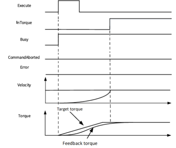
SDO instruction
MC_READSDO reads SDO data
MC_READSDO
This instruction is used to read the value of the servo object dictionary.
- [ MC_READSDO (S1) (S2) (S3) (D1) (S4) ]
Content, range and data type
| Parameter | Content | Range | Data type | Data type (Table) |
|---|---|---|---|---|
| (S1) | Object dictionary index | - | Unsigned BIN16 | ANY16_U |
| (S2) | Object dictionary subindex | - | Unsigned BIN16 | ANY16_U |
| (S3) | Length (BYTE unit) | - | Unsigned BIN16 | ANY16_U |
| (D1) | The read device | - | Define the size according to S3. | - |
| (S4) | Specify the servo station number | - | Signed BIN16 | ANY16_S |
Device used
| Instruction | Parameter | Devices | Index modification | Pulse expansion | |||||||||||||||||||||||||
|---|---|---|---|---|---|---|---|---|---|---|---|---|---|---|---|---|---|---|---|---|---|---|---|---|---|---|---|---|---|
| X | Y | M | S | SM | T(bit) | C(bit) | LC(bit) | HSC(bit) | D.b | KnX | KnY | KnM | KnS | T | C | D | R | SD | LC | HSC | K | H | E | [D] | XXP | ||||
| MC_READSDO | Parameter 1 | ● | ● | ● | ● | ● | ● | ||||||||||||||||||||||
| Parameter 2 | ● | ● | ● | ● | ● | ● | |||||||||||||||||||||||
| Parameter 3 | ● | ● | ● | ● | ● | ● | |||||||||||||||||||||||
| Parameter 4 | ● | ● | ● | ● | |||||||||||||||||||||||||
| Parameter 5 | ● | ● | ● | ● | ● | ● | |||||||||||||||||||||||
Features
▪Read the value according to the servo station number (S4), object dictionary index (S1), object dictionary subindex (S2), and length (S3) to the set device (D1).
MC_WRITESD0 writes SDO data
MC_WRITESDO
This instruction is used to write the value of the servo object dictionary.
-[MCWRITESDO (S1) (S2) (S3) (S4) (S5)]
Content, range and data type
| Parameter | Content | Range | Data type | Data type (Table) |
|---|---|---|---|---|
| (S1) | Object dictionary index | - | Unsigned BIN16 | ANY16_U |
| (S2) | Object dictionary sub-index | - | Unsigned BIN16 | ANY16_U |
| (S3) | Length (BYTE unit) | - | Unsigned BIN16 | ANY16_U |
| (S4) | The value to be written | - | Define the size according to S3. | - |
| (S5) | Specify the servo station number | - | Signed BIN16 | ANY16_S |
Device used
| Instruction | Parameter | Devices | Index modification | Pulse expansion | |||||||||||||||||||||||
|---|---|---|---|---|---|---|---|---|---|---|---|---|---|---|---|---|---|---|---|---|---|---|---|---|---|---|---|
| X | Y | M | S | SM | T(bit) | C(bit) | LC(bit) | HSC(bit) | D.b | KnX | KnY | KnM | KnS | T | C | D | R | SD | LC | HSC | K | H | E | [D] | XXP | ||
| MC_READSDO | Parameter 1 | ● | ● | ● | ● | ● | ● | ||||||||||||||||||||
| Parameter 2 | ● | ● | ● | ● | ● | ● | |||||||||||||||||||||
| Parameter 3 | ● | ● | ● | ● | ● | ● | |||||||||||||||||||||
| Parameter 4 | ● | ● | ● | ● | |||||||||||||||||||||||
| Parameter 5 | ● | ● | ● | ● | ● | ● | |||||||||||||||||||||
Features
▪The value of the device (S4) is written to the positions of the servo station number (S5), the object dictionary index (S1), the object dictionary sub-index (S2), and the length (S3).

Built-in variables of pulse axis system
The current state of the axis can be monitored in the program by its system variables.
| Name | Data type | Function |
| Cfg | AXIS_INFO_CFG_T | Axis configuration |
| wAxisID | WORD | Axis number (Read only) |
| wVersion | WORD | Version number (Read only) |
| wAxisType | WORD | Axis type (Read only): Bus servo axis Bus encoder axis |
| nEtherCATNo | DINT | EtherCAT axis number |
| nLocalID | DINT | Local axis ID. Y0/Y1 is 0; Y2/Y3 is 1; Y4/Y5 is 2; Y6/Y7 is 3. |
| bVirtualAxis | BOOL | Virtual axis or not |
| Cmd | AXIS_INFO_CMD_T | Setting value |
| fSetPosition | LREAL | Setting position (Read only) |
| fSetVelocity | LREAL | Setting speed (Read only) |
| fSetAcceleration | LREAL | Setting acceleration (Read only) |
| fSetDeceleration | LREAL | Actual deceleration (Read only) |
| fSetJerk | LREAL | Setting jerk (Read only) |
| fSetTorque | LREAL | Setting torque (Read only) Reserved |
| nLocalAxisSetPos | DINT | Local pulse axis setting position (Read only) |
| Act | AXIS_INFO_ACT_T | Current value |
| fActPosition | LREAL | Current position (Read only) |
| fActVelocity | LREAL | Current speed (Read only) |
| fActAcceleration | LREAL | Actual acceleration (Read only) |
| fActDeceleration | LREAL | Actual deceleration (Read only) |
| fActJerk | LREAL | Actual jerk (Read only) |
| fActTorque | LREAL | Current torque (Read only) Reserved |
| fFollowPos | LREAL | Following error (Read only) |
| nLocalAxisActPos | DINT | Local pulse axis current position (Read only) |
| nLocalAxisActFrequency | DINT | Local pulse axis current frequency (Read only) |
| Status | AXIS_INFO_STATUS_T | Axis status |
| wAxisState | WORD | Axis status (Read only) |
| Name | Data type | Function |
| wAxisError | DWORD | Axis error code (Read only) |
| wMotionState | WORD | Motion status (Read only) |
| bPowerState | BOOL | Axis enabled status (Read only) |
| bphLimit | BOOL | Hardware positive limit (Read only) |
| bnhLimit | BOOL | Hardware reverse limit (Read only) |
| bHomeState | BOOL | Homing limit (Read only) |
| bPsLimit | BOOL | Software positive limit (Read only) |
| bnsLimit | BOOL | Software reverse limit (Read only) |
| bTarDir | BOOL | Direction of motion (Read only) |
| Dbg | AXIS_DEBUG_T | Axis debugging information |
| bAxisDebug | BOOL | Axis debugging switch |
| bPower | BOOL | Axis enable |
| bStop | BOOL | Axis stop |
| bReset | BOOL | Axis reset |
| bJogP | BOOL | JOG+ |
| bJopN | BOOL | JOG- |
| bHome | BOOL | Homing |
| bSetPos | BOOL | Set the current position |
| bAbsPos | BOOL | Absolute positioning |
| bRevPos | BOOL | Reciprocating motion: |
| bRelPos | BOOL | Relative positioning |
| bVelocity | BOOL | Continuous motion |
| bTorque | BOOL | Torque Mode Reserved |
| fPresetPosition | LREAL | Preset position |
| fJogVelocity | LREAL | JOG speed |
| fPositionOffser | LREAL | Homing mode offset |
| fTarPosition | LREAL | Target position |
| fTarVelocity | LREAL | Target velocity |
| fTarAcceleration | LREAL | Target acceleration |
| fTarDeceleration | LREAL | Target deceleration |
| fTarJerk | LREAL | Target jerk |
| fTarPosition2 | LREAL | Target position 2 |
| Name | Data type | Function |
| fTarVelocity2 | LREAL | Target speed 2 |
| fTarAcceleration2 | LREAL | Target jerk 2 |
| fTarDeceleration2 | LREAL | Target deceleration 2 |
| fTarJerk2 | LREAL | Target jerk 2 |
| fTarTorque | LREAL | Target torque Reserved |
| fTarTorqueSlop | LREAL | Torque ramp Reserved |
| fLimitVelocity | LREAL | Limit the speed. Reserved |
| Pdo | AXIS_INFO_PDO_T | PDO information |
| wControlWord | WORD | Control word |
| wStatusWord | WORD | Status word |
| nSetPosition | DINT | Setting position |
| nActPosition | DINT | Current position |
| nSetVelocity | DINT | Setting speed |
| nActVelocity | DINT | Current speed |
| nSetTorque | DINT | Setting torque (Read only) Reserved |
| nActTorque | DINT | Current torque Reserved |
| nDO | DINT | Digital output Reserved |
| nDI | DINT | Digital input Reserved |
| wModesOfPperation | WORD | Control mode |
| wModesOfPperationDisplay | WORD | Current control mode |
| wTouchFunction | WORD | Touch probe function settings |
| wTouchStaus | WORD | Probe touch status |
| nTouch1PPos | DINT | Rising edge position of touch probe 1 |
| nTouch1NPos | DINT | Falling edge position of touch probe 1 |
| nTouch2PPos | DINT | Rising edge position of touch probe 2 |
| nTouch2NPos | DINT | Falling edge position of touch probe 2 |
| nMaxVelocity | DINT | Maximum velocity Reserved |
| pParam | AXIS_MODEPARAM_INFO_T | Parameter information |
| nEncoderMode | BYTE | Encoder model. |
| Name | Data type | Function |
0: Incremental mode 1: Absolute mode. | ||
| nModeSet | BYTE | Mode settings. 0: Linear mode 1: Rotation mode. |
| dRotatePeriod | LREAL | Rotation cycle |
| nSpeedADType | BYTE | Speed acceleration and deceleration type. 0: Default mode; 1: T-curve; 2: S-curve. |
| bEnSwLimit | BOOL | Whether to enable software limit |
| dSwPLimit | LREAL | Positive limit unit |
| dSwNLimit | LREAL | Reverse limit unit |
| dFollowThreShold | LREAL | Following error threshold Unit |
| dAxisMaxSpeed | LREAL | Axis maximum velocity unit/s |
| dAxisMaxASpeed | LREAL | Axis maximum acceleration unit/s^2 |
| dAxisMaxJogSpeed | LREAL | Axis Jog Maximum Speed Unit/s |
| nPMaxTorque | DINT | Positive torque maximum*0.1% |
| nNMaxTorque | DINT | Negative torque maximum*0.1% |
| bNoInErrorStop | BOOL | Don’t enter ErrorStop after hitting the limit status. Reserved |
| bHdPLimit | BOOL | Hardware positive limit 0: Positive logic; 1: Negative logic; Reserved: Not in use yet. |
| bHdNLimit | BOOL | Hardware reverse limit (Read-only) 0: Positive logic; 1: Negative logic; Reserved: Not in use yet. |
| bEnProbe1 | BOOL | Touch probe 1 enable Reserved |
| bEnProbe2 | BOOL | Touch probe 2 enable Reserved |
| sProbe1 | ARRAY[O..5] OF BYTE | Touch probe 1, X0 to X7. |
| sProbe2 | ARRAY[O..5] OF BYTE | Touch probe 2, X0 to X7. |
| nOutputWay | DWORD | Output mode 0: Pulse+Direction; 1: CW/CCW. |
| nCounterMode | DWORD | Counting mode 0: A/B phase 1 times frequency; |
| Name | Data type | Function |
1: A/B phase 2 times frequency; 2: A/B phase 4 times frequency; 3: CW/CCW; 4: Pulse+Direction; 5: Single phase count. | ||
nSignalSource |
DWORD | Signal source 0: X0-Phase A; 1: X1-Phase B; 2: X2-Phase A; 3: X3-Phase B. |
| bEnPreSet | BOOL | Preset enable |
| sInputTermial | ARRAY[O..5] OF BYTE | Input terminal |
| bEnCmpOutput | BOOL | Compare output enable |
| dPulseWidth | LREAL | Pulse width |
| sOutputTermial | ARRAY[O..5] OF BYTE | Output terminal |
| sCmpOutputUnit | ARRAY[O..4] OF BYTE | Compare output units ms/Unit |
| nFiltTime10ns | DINT | Filtering time design 10us unit |
| nFreqFilterTime | DINT | Velocity filtering time constant |
| pOrigin | AXIS_ORIGINRET_INFO_T | Homing information |
| nOriginSignal | BYTE | Homing signal 0: Not assigned; 1: Not used; 2: In use. |
| nZSingal | BYTE | Z signal. 0: Not assigned; 1: Not used; 2: In use. |
| nPLimit | BYTE | Positive limit 0: Not assigned; 1: Not used; 2: In use. |
| nNLimit | BYTE | Negative limit 0: Not assigned; 1: Not used; 2: In use. |
| nDirection | BYTE | Homing direction: 0: Not assigned; 1: Forward; 2: Reverse |
| nInputCheckDirection | BYTE | Enter the detection direction. 0: Not assigned; |
| Name | Data type | Function |
0: Positive 2: Reverse | ||
| nReturnList | BYTE | Homing list Homing mode 1 to 35 |
nReturnZero |
BYTE | Homing mode 0: Absolute homing 1: Relative homing. |
| dReturnSpeed | LREAL | Homing speed Unit/s |
| dReturnAccelerate | LREAL | Homing acceleration Uint/s^2 |
| dReturnNearSpeed | LREAL | Homing approach velocity Unit/s |
| nReturnTimeOut | DINT | Homing overtime time ms |
| bEnPLimit | BOOL | Positive limit enables |
| bEnNLimit | BOOL | Negative limit enable |
| bEnSignalLimit | BOOL | Homing signal enable |
| sPLimitAddr | ARRAY[O..5] OF BYTE | Positive limit address X0~X1023. (The local pulse axis currently only supports hardware limit X0-X7) |
| sNLimitAddr | ARRAY[O..5] OF BYTE | Reverse limit address X0~X1023. (The local pulse axis currently only supports hardware limit X0-X7) |
| sSignalLimitAddr | ARRAY[O..5] OF BYTE | Homing signal address X0 to X1023 (The local pulse axis currently only supports hardware limit X0-X7) |
| nPLimitLogic | BOOL | Forward limit logic 0: Forward logic; 1: Reverse logic. |
| nNLimitLogic | BOOL | Negative limit logic. 0: Positive logic; 1: Negative logic. |
| nSignalLogic | BOOL | Homing signal logic 0: Positive logic; 1: Negative logic. |
| pUnit | AXIS_UNITCONV_INFO_T | Unit information |
| bReverse | BOOL | Reverse or not |
| bEnGearBox | BOOL | Enable gearbox |
| nRotatePulseNum | DINT | The number of pulses for one revolution of the motor/encoder |
| dRotateMoveAmount1 | LREAL | Movement amount 1 in one rotation |
| dRotateMoveAmount2 | LREAL | Movement amount 2 in one rotation |
| nGearRatioM | INT | Gear ratio molecule |
| nGearRatioD | INT | Gear ratio denominator |
Others
Single axis motion control status diagram

Axis group motion control status diagram
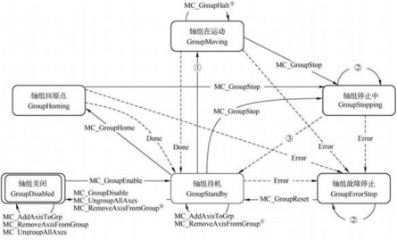
Arc mode description
| Mode | Border (CircMode=0) | Circle center (Circmode=1) | Diameter (CircMode=2) |
|---|---|---|---|
Features | The arc path consists of the starting point, auxiliary points, and ending point. |
The arc path consists of the starting point, the center point, and theending point.
| The arc is determined by its starting point, ending point, and the normal vector of the plane containing the circle. The direction of the vector determines the direction of CW and CCW circles. The vector length is the radius of the arc. |
Description | 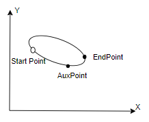 | 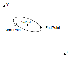 | 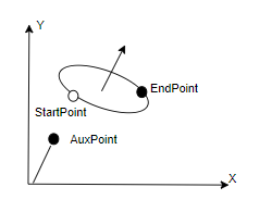 |
| Auxpoint | Arc path point | Center point of arc | Normal vector of the plane where the space arc lies |
Path choice | Invalid | CW and CCW circles CCW mode CW mode | Major and minor arcs 1: Minor arc 0: Major arc |
| Characteristics | Restriction of angle less than 2π for single instruction | Restriction of angle less than 2π and nor equal to π for single instruction | Restriction of angle less than 2π for single instruction The vector perpendicular to the circular plane must be calculated. |
Transition mode description
Detailed explanation of transition mode: Transition parameters are additional parameters of transition modes, which take effect according to different transition modes.
| TransitionMode | 0 (No buffer mode) | 1 (Largest velocity to buffer) | 2 (Specified velocity buffer) |
|---|---|---|---|
| TransitionParameter | Invalid | Invalid | Specified velocity |
Mode selection instructions
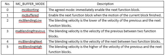
| Caution |
|---|
It should be noted that if the moving function block is interrupted by another function block, the following error will occur: braking distance is insufficient due to the limitation of deceleration; Note that in all the sequence diagrams explained below, some of the sequence diagrams for the status word feedback are incorrect. For example, in Figure 8-2, the start signal is not automatically set by the system after triggering, but controlled by the user. Function block triggers execution logic when on the rising edge. Likewise, the Done signal is not set automatically. When the function block ends, Done will be set until the falling edge of Execute is generated! |
(1) mcAborting
It is an agreed pattern without buffering. When the status of the application axis is changed to "ErrorStop", all motion control function blocks with buffer mode will enter mcAborting.
At this time, the function block output "Error" in mcAborting is set. Its subsequent commands are rejected because the output Error is set, so Active is reset.
The following figure illustrates the function connection of the front and back function block instances in mcAborting.
Figure8-1
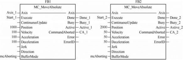
As shown in Figure 8-1, the previous and next motion control function blocks are MC_MoveAbsolute, and both adopt mcAborting.
The following Figure 8-2 shows the sequence diagrams of function block instances FB1 and FB2. Figure 8-2(a) shows the sequence diagram of two absolute position motion function blocks under normal working conditions, i.e., the motion controlled by FB2 is carried out after the motion controlled by FB1 is completed.
When on the Start_1=TRUE rising edge, the function block instance FB1 is activated. At the same time, the outputs Busy_1 and Active_1 are set. The motion process of the axis is as follows: the velocity increases to 100u/s according to the acceleration of 100u/s2, and keep the axis move at constant velocity. Then the velocity decreases to 0 with deceleration of 100u/s2, thus moving the axis to 1000u.
Then the output Done 1 is set, and Busy 1 and Active 1 are reset.
Axis position is 1000u.
Figure8-2 The sequence diagram of normal working condition and mcAborting
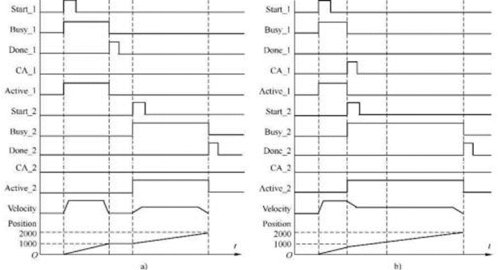
When on the Start_2=TRUE rising edge, the second function block instance FB2 is activated. The output Busy_2 and Active 2 are set. According to the acceleration of 50u/s2, the axis velocity increases to the constant velocity of 50u/s. Then the axis velocity decreases to 0 at the deceleration of 50u/s. The axis position is from 1000u to 2000u.
Since the absolute position has been reached, output Done_2 is set and Busy_2 and Active_2 are reset. Axis position is 2000u.
Figure 8-2(b) shows the sequence diagrams of two absolute position motion function blocks in mcAborting. On the rising edge of start1 = TRUE, the function block instanceFB1is activated.
At the same time, the output Busy_2 and Active_1 are set. The axis motion velocity increases according to the acceleration of 100u/s2. But in this process, the output start 2 of the function block instance FB2 is set, which abort the motion of the previous function block instance FB1. At this time, the axis dose not reach the required position 1000u and is aborted to stop.
As the function block instance FB2 is activated, Busy_2 and Active_2 are set. According to the requirement of the function block instance FB2, the velocity of the axis decreases to the input value of 50u/s2 according to its deceleration of 50u/s2. Keep it move at the constant velocity of 50u/s so that it will finally reach the position 2000u.
It can be seen that the activation of the next function block causes the previous function block to stop its motion, and the aborting command immediately affects the motion of the axis.
This buffer mode is called mcAborting.
(2) mcBuffered
The command of the next function block is stored in the buffer area. The command of the buffer area is executed only after the motion of the previous function block is completed. Therefore, this mode is called mcBuffered.
The BufferMode input for the next function block is set to be buffered mode (mcBuffered). Figure 8-3shows the setting for the connection of two function blocks.
The sequence diagram of mcBuffered is shown in Figure 8-4. In the figure, FB1 is activated when the input start 1=TRUE of the previous function block instance is on the rising edge. When this function block instance FB1 control the axis to move, the start 2 of the next function block instance FB2 is set. Due to the FB2 buffer mode is set to mcBuffered, the activation of FB2 does not abort the control of FB1 to the axis. Although the output Busy_2 of FB2 is set, the function block is not activated, namely, the output Active_2 is still FALSE.
Therefore, FB1 continues to control the motion of the axis until the axis reaches the set position 1000u. Then FB2 is immediately activated to work, and the velocity of the axis is not delayed. Increase the velocity to 50u/s based on the acceleration of 50u/s2 directly and then keep it move at the constant velocity of 50u/s, so that it will finally reach the position of 2000.
Figure8-3 Connections in mcBuffered
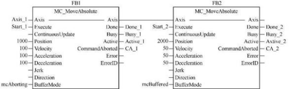
It can be seen from the figure that the buffer mode of the rear function block is set to mcBuffered, which means that the rear function block cannot interrupt the motion of the previous function block. And once the previous function block completes its task.
and Done_1 is set, the work of the next function block will start immediately.
The mcBuffered indicates that the motion command of the next function block has been stored in the buffer area, which does not affect the control and operation of previous motion control function block over the axis. It can execute subsequent commands after the executed function block outputs Done or Inxxx becomes TRUE.
Figure 8-4
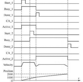
mcBlending
There are four options for mcBlending of the previous and next function blocks. The mcBlending represents the blending of the velocity of the previous and next functional blocks. In this case, the previous function block interrupts its motion, and the next function block controls the subsequent motion, but its initial velocity is called blending velocity or mixing velocity.
The mixing velocity can adopt the velocity of two function blocks (whichever is lower or higher) or it can be directly specified that the velocity of the previous function block or the velocity of the next function block is adopted.
Therefore, the mcBlending is divided into four types.
(1) mcBlendingLow.
The blending velocity is the lower of the set velocity of the two function blocks. This mcBlending can be random. If the set velocity of the previous function block is lower than that of the next function block, the blending velocity adopts the velocity of the previous function block.
On the contrary, if the set velocity of the previous function block is higher than that of the next function block, the blending velocity adopts the velocity of the next function block.
When the buffer mode of the next function block is set to be mcBlendingLow, it means that the next function block will not interrupt the work of previous function block if the work of the previous function block is not completed; when the velocity of the previous function block decreases to the lower velocity of the previous and next function blocks, the next function block can continue to control the motion of the axis.
Figure 8-5 shows the connection diagram of three motion blocks, and the mode of latter two function blocks are set to be mcBlendingLow.
Figure 8-5 The connection of mcBlendingLow
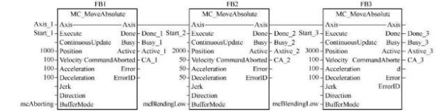
Figure 8-6 shows the sequence diagram of mcBlendingLow. To illustrate maBlendingLow, two subsequent function block instance FB2 and FB3 are used in the figure. In the figure, FB1 is activated when start_1 is set on the rising edge and then its BusY_1 is set. When FB1 controls the axis to move, start=2 of the FB2 instance is also set on the rising edge. FB1 does not complete the axis motion, so the Buffer-Mode of FB2 is set to mcBlendingLow.
Therefore, FB1 adopts the minimum velocity after blending FB1 and FB2, namely, the set velocity of FB2 of 50u/s.
It means that in the subsequent motion of FB1, the velocity of the axis is reduced to 50u/s according to the deceleration of FB2. When the axis velocity drops to the mixed low velocity, the FB1 control axis moves to the set position of 1000u, and the output Done_1 of FB1 is set, which indicates the end of its controlled motion.
FB2 immediately controls the axis to move at a constant velocity of 50u/s, and the axis is moving to specified position of 2000u.
At this time, if the Start_3 of the function block instance FB3 is set, since FB2 has not reached its position of 2000u, and the Buffer-Mode of FB3 is set to be mcBlendingLow, when the Start_3 of FB3 is set, the moving axis will control the axis according to the set velocity of FB2 and FB3 (whichever is lower) until the position of the axis reaches the set position of 2000u, then the output Active_2 is reset when FB2 is activated.
At this time, if the Start_3 of the function block instance FB3 is set, since FB2 has not reached its position of 2000u, and the Buffer-Mode of FB3 is set to be mcBlendingLow, when the Start_3 of FB3 is set, the moving axis will control the axis according to the set velocity of FB2 and FB3 (whichever is lower) until the position of the axis reaches the set position of 2000u, then the output Active_2 is reset when FB2 is activated. Then under the control of the FB3 function block instance, increase the velocity of the axis to 100u/s; then keep the axis move at constant velocity, and finally reduce the velocity to 0u/s; at this time the axis reaches the set position of 3000u.
Figure 8-6 The sequence diagram of mcBlendingLow
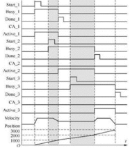
mcBlending means that due to the difference in the set velocity of the previous and next function blocks, when the Execute rising edge input of the next function block is set, the system will determine what velocity should be adopted to control the axis according to the BufferMode parameter set by the next function block.
The aforesaid mcBlendingLow adopts the set velocity of the two function blocks (whichever is lower).
The previous function block will complete the subsequent motion under the control of blending velocity until it reaches the set position, and the subsequent function block will continue to control the axis. mcBlendingPrevious: the blending velocity adopts the velocity set by the previous function block.
mcBlendingPrevious
As shown in Figure 8-5, if the BufferMode parameter of FB2 and FB3 is set to be mcBlendingPrevious, the blending velocity directly adopts the velocity of the previous function block.
Figure 8-7 shows the timing diagram of the mcBlendingPrevious.
When analyzing the sequence diagram, pay attention to the change of blending velocity. As shown in Figure 8-7, in the timing diagram of the mcBlendingPrevious, when FB1 is in buffer mode, the axis moves according to the velocity of the previous function block FB1, i.e., 100u/s, until it reaches the set position of 1000u.
When FB2 is in buffer mode, the axis moves according to the velocity of the previous function block FB2, i.e., 50u/s, until it reaches the set position of 2000u.
Therefore, the axis velocity is100u/s when FB1 output Active is reset, and the axis velocity is 50u/s when FB2 output Active is reset.
Figure 8-7 Sequence diagram of mcBlendingPrevious
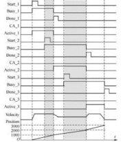
mcBlendingNext
As shown in Figure 8-5, if the BufferMode parameter of FB2 and FB3 is set to be mcBlendingNext, the blending velocity directly adopts the velocity of the next function block.
Figure 8-8 shows the timing diagram of the mcBlendingNext.
As shown in Figure 8-8, in the timing diagram of the mcBlendingNext, when FB1 is in buffer mode, the axis moves according to the velocity of the next function block FB2, i.e., 50u/s,
until it reaches the set position of 1000u. When FB2 is in buffer mode, the axis moves at 100U/S according to the velocity of the next function block FB3, until it reaches the set position of 2000U. Therefore, the axis velocity is 50u/s when the FB1 output Active is reset, and the axis velocity is 50u/s when FB2 output Active is reset.
As shown in Figure 8-6 of the sequence diagram of the mcBlendingLow, when FB1 is in buffer mode, the axis buffers at the low blending velocity and moves at 50U/S according to the velocity of FB2, until it reaches the set position of 1000U.
When FB2 is in buffer mode, the axis buffers at the low blending velocity and moves at 50U/S according to the velocity of the FB2, until it reaches the set position of 2000U.
Therefore, the axis velocity is 50u/s when the FB1 output Active is reset, and the axis velocity is 50u/s when FB2 output Active is reset.
Error Code Cross-reference Table
| Error Code | Error Definition | Interpretation |
|---|---|---|
| Normal | ||
| 0x00 | MC_ERROR_ID_SUCCESS | No error |
| Run-time error | ||
| 0x00200000 | MC_ERROR_ID_SCURVE_NOTFEASIBLE | Not feasible to compute S-curve |
| 0x00200001 | MC_ERROR_ID_SCURVE_MAXVEL_NOTREACHED | Not reach maximum velocity |
| 0x00200002 | MC_ERROR_ID_SCURVE_MAXACC_NOTREACHED | Not reach maximum acceleration |
| 0x00200003 | MC_ERROR_ID_SCURVE_FINDMAXACC_FAILED | Fail to find maximum velocity |
| 0x00200004 | MC_ERROR_ID_SCURVE_INVALIDINPUT | Invalid constraint for S-curve planning |
| PLCOpen State-machine error | ||
| 0x00300000 | MC_ERROR_ID_AXIS_STATE_VIOLATION | Invalid axis state violation |
| 0x00300001 | MC_ERROR_ID_POWER_ON_OFF_FROM_ERROR_STOP | Try to power on the servo at ErrorStop |
| 0x00300002 | MC_ERROR_ID_INVALID_STATE_FROM_STOPPING | Invalid state transition at Stopping |
| 0x00300003 | MC_ERROR_ID_INVALID_STATE_FROM_ERROR_STOP | Invalid state transition at ErrorStop |
| 0x00300004 | MC_ERROR_ID_INVALID_STATE_FROM_DISABLED | Invalid state transition at Disabled |
| 0x00300005 | MC_ERROR_ID_INVALID_STATE_FROM_POWERED | Invalid state transition at Powered |
| 0x00300006 | MC_ERROR_ID_INVALID_STATE_FROM_SYNC | Invalid state transition at Sync |
| 0x00300007 | MC_ERROR_ID_INVALID_STATE_NOT_HOME | Invalid state transition when not home |
| 0x00300008 | MC_ERROR_ID_INVALID_STATE_TO_DISABLED | Invalid state transition to Disabled |
| 0x00300009 | MC_ERROR_ID_INVALID_STATE_TO_ERRORSTOP | Invalid state transition to ErrorStop |
| 0x0030000A | MC_ERROR_ID_INVALID_STATE_TO_STANDSTILL | Invalid state transition to StandStill |
| 0x0030000B | MC_ERROR_ID_INVALID_STATE_TO_HOMING | Invalid state transition to Homing |
| 0x0030000C | MC_ERROR_ID_INVALID_STATE_TO_STOPPING | Invalid state transition to Stoppping |
| 0x0030000D | MC_ERROR_ID_INVALID_STATE_TO_DISCRETE | Invalid state transition to DiscreteMotion |
| 0x0030000E | MC_ERROR_ID_INVALID_STATE_TO_SYNC | Invalid state transition to SynchronizedMotion |
| 0x0030000F | MC_ERROR_ID_INVALID_STATE_TO_CONTINUOUS | Invalid state transition to ContinuousMotion |
| Error due to user/system limitations | ||
| 0x00400000 | MC_ERROR_ID_MOTION_LIMIT_ERROR | Velocity, acceleration or position over limit |
| 0x00400001 | MC_ERROR_ID_INVALID_DIRECTION_POSITIVE | No positive direction motion allowed |
| 0x00400002 | MC_ERROR_ID_INVALID_DIRECTION_NEGATIVE | No negative direction motion allowed |
| 0x00400003 | MC_ERROR_ID_VELOCITY_OVER_LIMIT | Velocity over limit |
| 0x00400004 | MC_ERROR_ID_ACCELERATION_OVER_LIMIT | Acceleration over limit |
| 0x00400005 | MC_ERROR_ID_POSITION_OVER_POSITIVE_LIMIT | Position over positive limit |
| 0x00400006 | MC_ERROR_ID_POSITION_OVER_NEGATIVE_LIMIT | Position over negative limit |
| 0x00400007 | MC_ERROR_ID_POSITION_LAG_OVERLIMIT | Position lag over limit |
| 0x00400008 | MC_ERROR_ID_TORQUE_OVER_LIMIT | Torque over limit |
| Error Stop | ||
| 0x00500000 | MC_ERROR_ID_AXIS_ERROR_STOP | Axis error stopped |
| Error from servo | ||
| 0x00600000 | MC_ERROR_ID_AXIS_ERROR_STOP | Servo has no error |
| 0x00600001 | MC_ERROR_ID_SERVO_FIELDBUS_INIT_ERROR | Servo fieldbus initialize error |
| 0x00600002 | MC_ERROR_ID_SERVO_POWER_ERROR | Servo power error |
| 0x00600003 | MC_ERROR_ID_SERVO_POWERING_ON_ERROR | Servo has error during powering on |
| 0x00600004 | MC_ERROR_ID_SERVO_ERROR_WHEN_POWERED_ON | Servo has error after powered on |
| 0x00600005 | MC_ERROR_ID_SERVO_POWERING_OFF_ERROR | Servo has error during powering off |
| 0x00600006 | MC_ERROR_ID_SERVO_PDO_NOT_MAP | Servo PDO not map |
| 0x00600007 | MC_ERROR_ID_SERVO_PDO_READ_ERROR | Servo PDO read error |
| 0x00600008 | MC_ERROR_ID_SERVO_PDO_WRITE_ERROR | Servo PDO write error |
| 0x00600009 | MC_ERROR_ID_SERVO_POWER_OFF | Servo can’t run in power off |
| 0x0060000A | MC_ERROR_ID_SERVO_ERROR_HOME_STATE | Servo has error when homing state |
| 0x0060000B | MC_ERROR_ID_SERVO_HOME_MODE_SWITCH | Servo mode switch error |
| 0x0060000C | MC_ERROR_ID_SERVO_HOME_CTRLWORD | Servo set homing mode error |
| 0x0060000D | MC_ERROR_ID_SERVO_HOME | Servo homing error |
| 0x0060000E | MC_ERROR_ID_SERVO_PDO_READ_BUSY | Servo PDO read busy |
| 0x0060000F | MC_ERROR_ID_SERVO_TOUCHPROBE_NOTFIND | Fail to find Servo TouchProbe |
| 0x00600010 | MC_ERROR_ID_SERVO_PARAREAD | Read Servo parameter error |
| 0x00600011 | MC_ERROR_ID_SERVO_PARAWRITE | Write Servo parameter error |
| 0x00600012 | MC_ERROR_ID_LOCAL_PULSE_HOME_TIMEOUT | Time out when origin regression |
| 0x00600013 | MC_ERROR_ID_LOCAL_PULSE_HOME_NOT_TOUCH_LIMI | The execution has not encountered the limit |
| 0x00600014 | MC_ERROR_ID_LOCAL_PULSE_HOME_VELOCITY_ OVER_LIMIT | Pulse shaft HOME Velocity over limit |
| 0x00600015 | MC_ERROR_ID_LOCAL_PULSE_HOME_ACC_ OVER_LIMIT | Pulse shaft HOME Acceleration over limit |
| 0x00600020 | MC_ERROR_ID_MODE_SWITCH_NEEDPDO_ NOTMAP | There is no required PDO for the mode corresponding to mode switching. |
| 0x006000FF | MC_ERROR_ID_SERVO_LOST | Servo lost |
| Axis’s error | ||
| 0x00700000 | MC_ERROR_ID_AXIS_GENERAL_ERROR | Axis's general error |
| 0x00700001 | MC_ERROR_ID_AXIS_ADD_QUEUE_ERROR | Axis’ add error |
| 0x00700002 | MC_ERROR_ID_AXIS_IS_UNHEALTHY | Axis is unhealthy |
| 0x00700003 | MC_ERROR_ID_AXIS_IS_OVER_LIMIT | Axis's motion instruction is over limit |
| 0x00700004 | MC_ERROR_ID_AXIS_FALLINGEDGE_ERROR | Axis error when on the falling edge |
| 0x00700005 | MC_ERROR_ID_AXIS_NOTFIND | Not find the axis |
| 0x00700006 | MC_ERROR_ID_AXIS_IS_INGROUP | Axis is in Group |
| 0x00700007 | MC_ERROR_ID_AXIS_CAN_NOT_SETPOS | Axis cannot be set position in current state |
| 0x00700008 | MC_ERROR_ID_AXIS_NOT_POWER | Axis does not power on yet |
| 0x00700009 | MC_ERROR_ID_AXIS_NOT_SUPPORTED_TOUCH | Not support the bound touch probe number |
| 0x0070000A | MC_ERROR_ID_AXIS_IS_COMBINED | Axis is combined |
| 0x0070000B | MC_ERROR_ID_AXIS_CAN_NOT_COMBINE_WHILE_RU N | Axis can't combine while running |
| 0x0070000C | MC_ERROR_ID_AXIS_GROUP_NOTFIND | Not find axis group number |
| General FB error | ||
| 0x00800000 | MC_ERROR_ID_FB_GENERAL_ERROR | User's FB run error |
| 0x00800001 | MC_ERROR_ID_FB_READ_PARAM_ERROR | User's FB read error |
| 0x00800002 | MC_ERROR_ID_FB_STOP_ERROR | User's FB stop error |
| 0x00800003 | MC_ERROR_ID_FB_NOT_BIND_AXIS | User's FB does not bind the logic axis |
| 0x00800004 | MC_ERROR_ID_FB_NOT_SET_PARAMETER_ID | User's FB dose not set the read parameter |
| 0x00800005 | MC_ERROR_ID_FB_NOT_IN_QUEUE | User's FB has already done and can't update |
| 0x00800006 | MC_ERROR_ID_FB_PARAMETER_ERROR | User's FB parameter error |
| 0x00800007 | MC_ERROR_ID_FB_PLAN_FAILED | User's FB error due to parameter when executing planning |
| 0x00800008 | MC_ERROR_ID_FB_REPLACE_AXIS_IN_RUN | User's FB replace axis in running |
| 0x00800009 | MC_ERROR_ID_FB_HALTSUPERIMPOSED_ERROR | Stop virtual superimposed error |
| 0x0080000A | MC_ERROR_ID_FB_NOT_BIND_AXIS_GROUP | User's FB isn't binding axis in axis group |
| 0x0080000B | MC_ERROR_ID_FB_BIND_AXIS_IS_ERROR | The bound axis has error |
| 0x0080000C | MC_ERROR_ID_FB_MINE_AXIS_IS_ERROR | Fb’s planning axis has error |
| 0x0080000D | MC_ERROR_ID_FB_NOT_BIND_MASTER | FB does not bind master axis |
| 0x0080000E | MC_ERROR_ID_FB_NOT_BIND_SLAVE | FB does not bind slave axis |
| 0x0080000F | MC_ERROR_ID_FB_CAN_NOT_BIND_ENCODERAXIS | FB can't bind encoder axis |
| 0x00800010 | MC_ERROR_ID_FB_NOT_BIND_TRIGGER_INFO | FB does not bind trigger information |
| 0x00800011 | MC_ERROR_ID_FB_NOT_SUPPORTED_TRINUM | Bound trigger number is not supported |
| 0x00800012 | MC_ERROR_ID_FB_CAN_NOT_CHANGE_WHILE_RUN | FB’ bound parameter cannot change at running |
| 0x00800013 | MC_ERROR_ID_FB_RANGE_SET_ERROR | FB parameter range has error. Maximum value may be less than minimum value. |
| 0x00800014 | MC_ERROR_ID_FB_MASTER_SLAVE_ARE_SAME | FB master and slave axis are consistent |
| 0x00800015 | MC_ERROR_ID_FB_MASTER_AUXILIARY_ARE_SAME | FB master and auxiliary axis are consistent |
| 0x00800016 | MC_ERROR_ID_FB_AUXILIARY_SLAVE_ARE_SAME | FB auxiliary and slave axis are consistent |
| 0x00800017 | MC_ERROR_ID_FB_MASTER_SLAVE_NOT_ASCENDING | FB master and slave id are not in ascending order |
| General axis group error | ||
| 0x00900000 | MC_ERROR_ID_AXIS_GROUP_GENERAL_ERROR | Group general error |
| 0x00900001 | MC_ERROR_ID_AXIS_GROUP_ADD_QUEUE_ERROR | Group fb add error |
| 0x00900002 | MC_ERROR_ID_AXIS_GROUP_REMOVE_ERROR | Group remove logic axis error |
| 0x00900003 | MC_ERROR_ID_AXIS_GROUP_ENABLE_ERROR | Group enable error |
| 0x00900004 | MC_ERROR_ID_AXIS_GROUP_DISABLE_ERROR | Group disable error |
| 0x00900005 | MC_ERROR_ID_AXIS_GROUP_STOP_ERROR | Group stop error |
| 0x00900006 | MC_ERROR_ID_AXIS_GROUP_AXIS_INSINGLEMOVE | Group is to run, but axis is in single axis controlled |
| 0x00900007 | MC_ERROR_ID_AXIS_GROUP_AXIS_INGROUPMOVE | Axis is bound in axis group |
| 0x00900008 | MC_ERROR_ID_AXIS_GROUP_IS_UNHEALTHY | Group's any axis is error or any error in group |
| 0x00900009 | MC_ERROR_ID_AXIS_GROUP_CAN_NOT_SETPOT | Group can't set position |
| 0x0090000A | MC_ERROR_ID_AXIS_GROUP_INVALID_STATE_TRANS | Group is to switch to the unallowed state |
| 0x0090000B | MC_ERROR_ID_AXIS_GROUP_NOT_BIND_AXIS | Group does not bind axis |
| 0x0090000C | MC_ERROR_ID_AXIS_GROUP_IS_DISABLED | Group is disabled |
| Single axis planner error | ||
| 0x00A00000 | MC_ERROR_ID_PLANNER_DIST_IS_ZERO | Planner position is 0 |
| 0x00A00001 | MC_ERROR_ID_PLANNER_SPPED_IS_ZERO | Planner velocity is 0 |
| 0x00A00002 | MC_ERROR_ID_PLANNER_ACC_DES_IS_ZERO | Planner acceleration is 0 |
| 0x00A00003 | MC_ERROR_ID_PLANNER_JERK_IS_ZERO | Group general error |
| 0x00A00004 | MC_ERROR_ID_PLANNER_CURRENT_DIFF_LAST | Planner synchronization error, current position is inconsistent with the last position |
| 0x00A00005 | MC_ERROR_ID_PLANNER_SPPED_OVER_LIMIT | Planner input velocity is over limit |
| 0x00A00006 | MC_ERROR_ID_PLANNER_ACC_DES_OVER_LIMIT | Planner input acceleration and deceleration is over limit |
| 0x00A00007 | MC_ERROR_ID_PLANNER_JERK_OVER_LIMIT | Planner input Jerk is over limit |
| 0x00AFFFFF | MC_ERROR_ID_PLANNER_SG_CULCULATE | Planner single axis calculate error |
| Axis group planner error | ||
| 0x00B00000 | MC_ERROR_ID_PLANNER_SP_SAME_START_END | Planner space curve’ start and end are the same |
| 0x00B00000 | MC_ERROR_ID_PLANNER_SP_NOT_IN_SAME_PLANE | Planner space curve is not in the same plane |
| 0x00BFFFFF | MC_ERROR_ID_PLANNER_SP_CULCULATE | Planner space curve calculate error |
| ECAM or EGEAR error | ||
| 0x00C00000 | MC_ERROR_ID_AXIS_MASTER_AND_SLAVE_IS_SAME | Planner master and slave is the same |
| 0x00C00001 | MC_ERROR_ID_AXIS_MAX_ACC_OR_DEC_OR_VEL_IS_ZERO | Planner axis's max acc/dec/vel is zero |
| 0x00C00002 | MC_ERROR_ID_CAM_TABLE_IS_INEXISTENCE | Planner the camtable is inexistence |
| 0x00C00003 | MC_ERROR_ID_CAM_NODENUM_OVER_NODE_SIZE | Planner the cam node num is over actual cam node size |
| 0x00C00004 | MC_ERROR_ID_CAM_NODENUM_OR_NODESIZE_IS_ERROR | Planner the cam node num or cam node size is error |
| 0x00C00005 | MC_ERROR_ID_CAM_FIRST_NODE_POS_NON_ZERO | Planner the cam first node's master position or slave position non-zero |
| 0x00C00006 | MC_ERROR_ID_CAM_NODE_PARAMETER_IS_ERROR | Planner the cam node parameter is error |
| 0x00C00007 | MC_ERROR_ID_CAM_UPDATE_CAM_TABLE_IS_ERROR | Planner the update cam table is error |
| 0x00C00008 | MC_ERROR_ID_CAM_SAVE_CAM_TABLE_IS_ERROR | Planner the save cam table is error |
| 0x00C00009 | MC_ERROR_ID_CAM_GET_AXIS_VEL_AND_POS_ERROR | Planner get master and slave vel/pos is error |
| 0x00C0000A | MC_ERROR_ID_BUFFER_MODE_IS_NOT_ABORTING | Planner the buffer mode is not aborting |
| 0x00C0000B | MC_ERROR_ID_CAM_AXIS_SCALING_IS_ZERO | Planner the cam master scaling or slave scaling is zero |
| 0x00C0000C | MC_ERROR_ID_CAM_TABLE_IS_NOT_BIND | Planner the cam table is not bind |
| 0x00C0000D | MC_ERROR_ID_THE_AXIS_IS_NOT_IN_CAM_STATE | Planner the axis is not in the cam state |
| 0x00C0000E | MC_ERROR_ID_THE_AXIS_IS_NOT_IN_GEAR_STATE | Planner the axis is not in the gear state |
| 0x00C0000F | MC_ERROR_ID_CAM_IN_PARAMETER_IS_ERROR | Planner the camin parameter is error |
| 0x00C00010 | MC_ERROR_ID_GEAR_IN_PARAMETER_IS_ERROR | Planner the gearin parameter is error |
| 0x00C00011 | MC_ERROR_ID_GEAR_IN_POS_PARAMETER_IS_ERROR | Planner the gearinpos parameter is error |
| 0x00C00012 | MC_ERROR_ID_CAM_TABLE_IS_UPDATE | Planner the cam table is updating |
| 0x00C00013 | MC_ERROR_ID_GET_CAM_TABLE_POS_IS_ERROR | Planner the get cam table position is error |
| 0x00C00014 | MC_ERROR_ID_CAM_TABLE_PHASE_IS_OUT_OF_RANGE | Planner the get cam table position is error |
| 0x00C00015 | MC_ERROR_ID_CAM_TABLE_NODE_IS_NOT_ADJOIN | Planner the cam table node is not adjoin |