Communication Port Protocol Setting
Communication port protocol setting
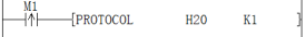
PROTOCOL(P)
Set (s) protocol for (n) communication port.
-[PROTOCOL (s) (n)]
Content, range and data type
| Parameter | Content | Range | Data type | Data type (label) | Custom variable type |
|---|---|---|---|---|---|
| (s) | Protocol number to be set | - | Unsigned BIN16 bits | ANY16 | INT |
| (n) | Which communication port to be set, 0 means COM1, 1 means COM2 | 0, 1 | Unsigned BIN16 bits | ANY16 | INT |
Device used
| Instruction | Parameter | Devices | Index modification | Pulse expansion | |||||||||||||||||||||||
|---|---|---|---|---|---|---|---|---|---|---|---|---|---|---|---|---|---|---|---|---|---|---|---|---|---|---|---|
| X | Y | M | S | SM | T(bit) | C(bit) | LC(bit) | HSC(bit) | D.b | KnX | KnY | KnM | KnS | T | C | D | R | SD | LC | HSC | K | H | E | [D] | XXP | ||
| PROTOCOL | Parameter 1 | ● | ● | ● | ● | ● | ● | ● | ● | ● | ● | ● | ● | ||||||||||||||
| Parameter 2 | ● | ● | ● | ● | ● | ● | ● | ● | ● | ● | ● | ● | |||||||||||||||
Function
This command is mainly used to set the protocol during RUN, and can also be used in the first cycle of RUN.
The value of the protocol address (COM1 SD2542, COM2 SD2592) and the protocol modification sign (COM1 SD2543, COM2 SD2593) can be directly set according to the command parameters.
The specific calculation formula for setting the protocol modification sign (COM1 SD2543, COM2 SD2593) is: (parameter setting value + offset of the corresponding serial port's initial special device+ 10)*2
For example, setting the protocol to 2, i.e. (2 +2593-2590 +10)*2, which is (2+3+10) *2=30. At this time, SD2592 will be set to 1, and SD2593 will be set to 32.
Protocol number
| Protocol number | Content |
|---|---|
| 0H | Wecon Modbus slave station |
| 2H | Modbus RTU slave station |
| 3H | Modbus ASCII slave station |
| 10H | User-defined protocol |
| 20H | Modbus RTU master |
| 30H | Modbus ASCII master |
Related devices
| Devices | Content |
|---|---|
| SD2542 | COM1 protocol settings |
| SD2543 | COM1 protocol modification sign |
| SD2592 | COM2 protocol settings |
| SD2593 | COM2 protocol modification sign |
Precautions
The setting of communication parameters will affect the overall communication. The parameters in PLC are modified when there is no communication or after a round of communication is completed. Attention shall be paid to this point.
If the set protocol does not match the provided protocol number, the protocol modification flag (COM1 SD2543, COM2 SD2593) will not be cleared after setting. At this time, the protocol will not be set successfully, and it will run according to the original protocol.
Error code
| Error code | Content |
|---|---|
| 4085H | The read address (s) (n) exceeds the device range. |
| 4084H | (n) is not 1. |
Example
As shown in above example, M1 turns from OFF to ON during RUN process.
SD2594 will be set to 32 (20H), SD2595 will be set to 90 and then it will be cleared. At this time, it has been set successfully.

If M1 turns from OFF to ON again,
SD2592 will be set to 32 (20H), SD2595 will be set to 90, which will not be cleared.

Modbus Serial Port Parameter Setting
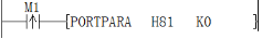
PORTPARA/Modbus serial port parameter setting
PORTPARA(P)
Set (s) serial port parameters for (n) communication port.
-[PORTPARA (s) (n)]
Content, range and data type
| Parameter | Content | Range | Data type | Data type (label) | Custom variable type |
|---|---|---|---|---|---|
| (s) | Serial port parameters to be set | - | Unsigned BIN16 bits | ANY16 | INT |
| (n) | Which communication port to be set, 0 means COM1, 1 means COM2 | 0, 1 | Unsigned BIN16 bits | ANY16 | INT |
Device used
| Instruction | Parameter | Devices | Index modification | Pulse expansion | |||||||||||||||||||||||
|---|---|---|---|---|---|---|---|---|---|---|---|---|---|---|---|---|---|---|---|---|---|---|---|---|---|---|---|
| X | Y | M | S | SM | T(bit) | C(bit) | LC(bit) | HSC(bit) | D.b | KnX | KnY | KnM | KnS | T | C | D | R | SD | LC | HSC | K | H | E | [D] | XXP | ||
| PORTPARA | Parameter 1 | ● | ● | ● | ● | ● | ● | ● | ● | ● | ● | ● | ● | ||||||||||||||
| Parameter 2 | ● | ● | ● | ● | ● | ● | ● | ● | ● | ● | ● | ● | |||||||||||||||
Function
This command is mainly used to set serial port parameters during RUN, and can also be used in the first cycle of RUN.
The value of serial port parameter address (COM1 SD2540, COM2 SD2590) and the serial parameter modification sign (COM1 SD2541, COM2 SD2591) can be set directly according to the command parameters.
The specific calculation formula for setting the serial port parameter modification sign (COM1 SD2541, COM2 SD2591) is: (parameter setting value + offset of the corresponding serial port's initial special device + 10)*2
For example, setting the COM1 serial port parameter to 193 (HC1), i.e. (193 +2541-2540 +10)*2 which is (193 +1+10) *2=408. At this time, SD2540 is set to be 193(HC1) and SD2541 is set to be 408.
Serial port parameter setting table
| Bit number | Name | Content | |
|---|---|---|---|
| 0 (bit OFF) | 1 (bit ON) | ||
| b0 | Data length | 7 digits | 8 digits |
b1 b2 | Parity check | b2, b1 (0, 0): None (0,1): Odd parity (ODD) (1,1): Even parity (EVEN) | |
| b3 | Stop bit | 1 bit | 2 bit |
b4 b5 b6 b7 b8 b9 | Baud rate(bps) | .b9,b8,b7,b6,b5,b4 ( 0, 0, 0, 1, 1, 1): 4800 ( 0, 0, 1, 0, 0, 0): 9600 ( 0, 0, 1, 0, 0, 1): 19200 ( 0, 0, 1, 0, 1, 0): 38400 ( 0, 0, 1, 0, 1, 1): 57600 | .b9,b8,b7,b6,b5,b4 ( 0, 0, 1, 1, 0, 0): 115200 ( 0, 0, 1, 1, 0, 1): 187500 ( 0, 0, 1, 1, 1, 0): 230400 ( 0, 0, 1, 1, 1, 1): 460800 ( 0, 1, 0, 0, 0, 0): 921600 |
| b10 | STX | Disable STX function | Enable STX function, the specific value is set by D8124 |
| b11 | ETX | Disable ETX function | Enable the ETX function, the specific value is set by D8125 |
| b12 | -- | -- | -- |
| b13 | -- | -- | -- |
| b14 | -- | -- | -- |
| b15 | -- | -- | -- |
Related devices
| Devices | Content |
|---|---|
| SD2540 | COM1 serial port parameter setting |
| SD2541 | COM1 serial port parameter modification sign |
| SD2590 | COM2 serial port parameter setting |
| SD2591 | COM2 serial port parameter modification sign |
Precautions
The setting of communication parameters will affect the overall communication. The parameters in PLC are modified when there is no communication or after a round of communication is completed. Attention shall be paid to this point.
STX function and ETX function are only useful in the case of user-defined protocol.
If the set protocol does not match the provided protocol number, the serial port parameter modification sign (COM1 SD2541, COM2 SD2591) will not be cleared after setting. At this time, the protocol will not be set successfully, and it will run according to the original protocol.
Error code
| Error code | Content |
|---|---|
| 4085H | The read address (s) and (n) exceeds the device range. |
| 4084H | (n) is not 0 or 1. |
Example
As shown in the above example,
M1 turns from OFF to ON during RUN process.
SD2540 will be set to 129 (H81, baud rate: 9600, stop bit: 1, data bit: 8, parity bit: none), SD2541 will be set to 280 and then cleared. At this time, it has been set successfully.

If M1 turns from OFF to ON again,
SD2540 will be set to 129 (H81), SD2541 will be set to 280, which will not be cleared.

Modbus Station Number Setting
STATION/Modbus station number setting
STATION (P)
Under the Modbus slave station protocol. Set the station number (s) for the (n) communication port.
-[STATION (s) (n)]
Content, range and data type
| Parameter | Content | Range | Data type | Data type (label) | Custom variable type |
|---|---|---|---|---|---|
| (s) | Station number to be set | 0~255 | Unsigned BIN16 bits | ANY16 | INT |
| (n) | Which communication port to set, 0 means COM1, 1 means COM2 | 0, 1 | Unsigned BIN16 bits | ANY16 | INT |
Device used
| Instruction | Parameter | Devices | Index modification | Pulse expansion | |||||||||||||||||||||||
|---|---|---|---|---|---|---|---|---|---|---|---|---|---|---|---|---|---|---|---|---|---|---|---|---|---|---|---|
| X | Y | M | S | SM | T(bit) | C(bit) | LC(bit) | HSC(bit) | D.b | KnX | KnY | KnM | KnS | T | C | D | R | SD | LC | HSC | K | H | E | [D] | XXP | ||
| STATION | Parameter 1 | ● | ● | ● | ● | ● | ● | ● | ● | ● | ● | ● | ● | ||||||||||||||
| Parameter 2 | ● | ● | ● | ● | ● | ● | ● | ● | ● | ● | ● | ● | |||||||||||||||
Function
This command is mainly used to set the station number during RUN, and can also be used in the first cycle of RUN.
The value of the station number address (COM1 SD2544, COM2 SD2594) and the station number modification sign (COM1 SD2545, COM2 SD2595) can be directly set according to the command parameters.
The specific calculation formula for setting the station number modification sign (COM1 SD2545, COM2 SD2595) is: (parameter setting value + offset of the corresponding serial port's initial special device + 10) *2
For example, setting COM2 station number to 1, i.e. (1 +2595 - 2590 +10) *2, which is (1 +5+10) *2=32. At this time, SD2594 will be set to 1, and SD2595 will be set to 32.
Note: Whether the value is set by self-calculation and then modifying the sign (COM1 SD2545, COM2 SD2595) to the station number, or by using this command, the station number can be modified when the PLC is in the RUN state.
Station number modification sign (COM1 SD2545 and COM2 SD2595): During RUN, when the station number and modification sign are set correctly (the correctness will be judged at the End of the program), it will be deemed as the correct first cycle; then the protocol and modification sign (COM1 SD2545, COM2 SD2595) will be cleared upon completion of modification and the same value that is consequently set will not be processed. It mainly aims to avoid repeated settings for multiple times.
Related devices
| Devices | Content |
|---|---|
| SD2544 | COM1 station number settings |
| SD2545 | COM1 station number modification sign |
| SD2594 | COM2 station number settings |
| SD2595 | COM2 station number modification sign |
Error code
| Error code | Content |
| 4085H | The read address (s) (n) exceeds the device range. |
| 4084H | (s) not within the range of 0~255. |
| (n) is not 0 or 1. |
Precautions
The setting of communication parameters will affect the overall communication. The parameters in PLC are modified when there is no communication or after a round of communication is completed. Attention shall be paid to this point.
Example

As shown in the above example,
M1 turns from OFF to ON during RUN process.
SD2594 will be set to 2, SD2595 will be set to 34 and then it will be cleared. At this time, it has been set successfully.

If M1 turns from OFF to ON again,
SD2594 will be set to 2, SD2595 will be set to 34 but will not be cleared.

RS Instruction
RS/External communication command
RS
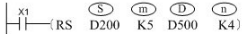
In Modbus master station protocol: the command is the setting interface for the master station to send protocol frames. According to the station number function code (s), slave station address (m), length (d) set by the command and the function code, it can be determined whether n data is required to automatically combine the transmission and reception of protocol frames. If it is a read type function code, the data will be written into (n).
-[RS (s) (m) (d) (n)]
Content, range and data type
| Parameter | Content | Range | Data type | Data type (label) | Custom variable type |
|---|---|---|---|---|---|
| (s) | The starting address of the register area where the data to be sent is stored. | - | Unsigned BIN16 bits | ANY16 | -- |
| (m) | The length (in bytes) of the data to be sent. | 0~523 | Unsigned BIN16 bits | ANY16 | -- |
| (d) | The starting number of the device that stores written data. | - | Unsigned BIN16 bits | ANY16 | -- |
| (n) | Volume of data written (in bytes). | 0~523 | Unsigned BIN16 bits | ANY16 | -- |
In Modbus protocol:
| Parameter | Content | Range | Data type | Data type (label) |
|---|---|---|---|---|
| (s) | The high byte stores the station number of the slave station, and the low byte stores the Modbus function code. | - | Unsigned BIN16 bits | ANY16 |
| (m) | Slave station address. The address provided by the slave station will read or write data from the address of slave station. | - | Unsigned BIN16 bits | ANY16 |
| (d) | Length, the data length read or written by Modbus, and the unit are determined by the function code. | - | Unsigned BIN16 bits | ANY16 |
| (n) | The starting address for data to be read or written. | - | Unsigned BIN16 bits | ANY16 |
Device used
| Instruction | Parameter | Devices | Index modification | Pulse expansion | |||||||||||||||||||||||
|---|---|---|---|---|---|---|---|---|---|---|---|---|---|---|---|---|---|---|---|---|---|---|---|---|---|---|---|
| X | Y | M | S | SM | T(bit) | C(bit) | LC(bit) | HSC(bit) | D.b | KnX | KnY | KnM | KnS | T | C | D | R | SD | LC | HSC | K | H | E | [D] | XXP | ||
| RS | Parameter 1 | ● | ● | ● | ● | ● | ● | ||||||||||||||||||||
| Parameter 2 | ● | ● | ● | ● | ● | ● | |||||||||||||||||||||
| Parameter 3 | ● | ● | ● | ● | ● | ● | |||||||||||||||||||||
| Parameter 4 | ● | ● | ● | ● | ● | ● | |||||||||||||||||||||
User-defined protocol
When the communication protocol is set as a user-defined protocol. When the contact in front of RS command is turned on and SM2591 is also turned on at the same time, if the sending length (m) is not 0, (m) bytes of the data of (s) will be sent out, and then it will enter the mode of waiting for reception. When the data is received, (N) bytes of data will be stored in (d). SM2593 will be turned ON after receiving (n) data.
In addition, when the sending length (m) is 0, it will be in the receive-only mode. When the receiving length (n) is 0, it will be in the send-only mode.
To enable the start character (STX) and the end character (ETX) modes of RS command, the status of the 10th and 11th bits of the special address SD2600 must be set. See the table below for detailed settings:
| Bit number | Name | Content | |
|---|---|---|---|
| 0 (bit OFF) | 1 (bit ON) | ||
| b0 | Data length | 7 digits | 8 digits |
b1 b2 | Parity check | b2, b1 (0, 0): None (0,1): Odd parity (ODD) (1,1): Even parity (EVEN) | |
| b3 | Stop bit | 1 bit | 2 bit |
b4 b5 b6 b7 b8 b9 | Baud rate (bps) | .b9,b8,b7,b6,b5,b4 ( 0, 0, 0, 1, 1, 1): 4800 ( 0, 0, 1, 0, 0, 0): 9600 ( 0, 0, 1, 0, 0, 1): 19200 ( 0, 0, 1, 0, 1, 0): 38400 ( 0, 0, 1, 0, 1, 1): 57600 | .b9,b8,b7,b6,b5,b4 ( 0, 0, 1, 1, 0, 0): 115200 ( 0, 0, 1, 1, 0, 1): 187500 ( 0, 0, 1, 1, 1, 0): 230400 ( 0, 0, 1, 1, 1, 1): 460800 ( 0, 1, 0, 0, 0, 0): 921600 |
| b10 | STX | Disable STX function | Enable STX function, the specific value is set by D8124 |
| b11 | ETX | Disable ETX function | Enable the ETX function, the specific value is set by D8125 |
| b12 | -- | -- | -- |
| b13 | -- | -- | -- |
| b14 | -- | -- | -- |
| b15 | -- | -- | -- |
Example
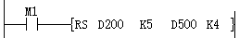
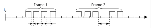
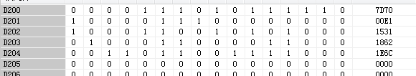
When M1 is ON, the sent and received data of communication are stored as follows after the command is executed:
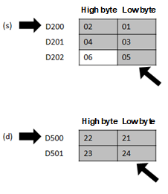
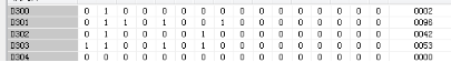
As shown in the figure, the sent data are 01H, 02H, 03H, 04H and 05H in turn The number of dark backgrounds used is the sent data length (m).
As shown in the figure, the received data are 21H, 22H, 23H and 24H in turn The number of dark backgrounds used is the received data length (n).
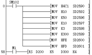
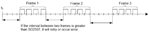
Some configuration and preparation of serial communication are needed for actual programming in order to achieve communication as expected. For instance, sending and receiving mode of serial port, baud rate, number of bits, parity, software protocol settings, timeout judgment conditions, and data preparation for the transceiver buffer, sending and receiving sign processing shall be set. A relatively complete RS communication setting program is shown as follows:

Set the protocol to a user-defined protocol,
Sending interval: 5ms,
Reception timeout: 100ms,
Retries: 3 times,
Character interval timeout: 30ms,
Sending starting address D200 of user-defined protocol: sending length 8,
Directly trigger sending upon being.
For detailed user-defined protocol instructions, please refer to “9.5.1 User-defined Protocol Description”.
Modbus protocol
When the protocol is set to Modbus master station protocol (whether it is RTU or ASCII), When the contact in front of the RS command is set ON. RS2 command will judge whether the data of (N) is needed to send the combined data frame according to station number function code (s), slave station address (m), the length (d) and function code.

After receiving, directly close the command and reset the command receiving sign.
| Parameter | Content |
|---|---|
| (s) | The high byte stores the station number of slave station, and the low byte stores the function code of Modbus. |
| (m) | Slave station address. The address provided by the slave station will read or write data from the address of slave station. |
| (d) | Length: the length read or written by Modbus. The unit is determined by function code. |
| (n) | The starting address for data to be read or written. |

Communication protocol setting:
Sending interval: 5ms
Reception timeout: 100ms
Timeout retry times: 3 times
Station number 01H, function code 03H, slave station
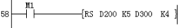
As shown in above ladder diagram:
When M1 is turned ON, PLC will send data (hexadecimal) from COM2 of PLC: 01 03 00 0A 00 05 A5 C8
01: represents slave address, the high 8 bits of (s);
03: Modbus command code, the low 8 bits of (s), which means to read the slave register;
00 0A: the address of slave register to be read, the value of (m);
00 05: the number of registers to be read, the value of (d),
A5 C8: CRC parity code.
For detailed user-defined protocol instructions, please refer to “9.5.2 Modbus Protocol Description”.
Precautions
- Although the RS command currently allows all the parameters of the command to use constants such as K and H, different protocols have different restrictions.
- When the protocol is a user-defined protocol, S and D cannot be constants, otherwise it will report (3189H) error.
- When the protocol is Modbus protocol, n cannot be a constant, otherwise it will report (3189H) error.
- The combination of RTU protocol and 7-bit data bits cannot be set.
- If the serial port parameter settings are different, it may still be able to communicate. At present, it is normal.
- Currently, the RS comand cannot be used in interrupts and events.
Error code
| Error code | Content |
|---|---|
| 4085H | (s), (m), (d) and (n) read address exceeds the range of the device. |
| 3180H | COM2 data reception error. There may be interference on the communication cable, it is recommended to connect GND. |
| 3181H | COM2 data reception timeout. Check the wiring, whether the serial port parameter settings correspond to master and slave, and whether there is interference. Check whether it is caused by the late response from the slave station. It is recommended to increase the sending interval SD2546. |
| 3182H | COM2 CRC parity error. There may be interference on the communication cable, it is recommended to connect GND. |
| 3183H | COM2 LRC parity error. There may be interference on the communication cable, it is recommended to connect GND. |
| 3184H | The COM2 station number is incorrectly configured. Check the slave station number setting, and check whether there is any problem with the receiving and sending mechanism from slave station. |
| 3185H | COM2 send buffer overflow If this error message appears, please contact technical personnel |
| 3186H | COM2 function code is wrong. Check whether the set function code is a function code supported by PLC. |
| 3187H | COM2 address is wrong. Check whether the slave station has this address. (Please refer to Modbus exception 02). |
| 3188H | The length of COM2 is wrong. Check whether the communication length exceeds the length range specified by Modbus protocol or user-defined protocol. |
| 3189H | COM2 data error. Check whether parameters of the command are wrong. Check whether the set value is supported by the slave station. (Please refer to Modbus exception 03). |
| 318AH | COM2 slave station is busy. Message returned from slave station: Slave station is busy. (Please refer to Modbus exception 06). |
| 318BH | COM2 slave station does not support function codes. Check whether this function code is supported by the slave station. (Please refer to Modbus exception 01). |
| 318CH | COM2 slave station is faulty. Message returned from slave station: Slave station failed, please check whether slave station failed. (Please refer to Modbus exception 04). |
| 318DH | COM2 slave station confirmation. Message returned from slave station: slave station confirmation. (Please refer to Modbus exception 05). |
| 318EH | At present, COM2 does not support this command or function. When the slave protocol is set, the communication commands related to master station or master station functions cannot be used. Please change the protocol or close the contact before the corresponding command or close the corresponding communication function. |
| 318FH | COM2 sending timeout. If this error message appears, please contact technical personnel. |
| 31A0H | No available gateway for COM2 Message returned from the slave station: no available gateway. (Please refer to Modbus exception 0A). |
| 31A1H | COM2 indicates that no response was obtained from the target device. Message returned from the slave station: The device is not networked. (Please refer to Modbus Exception 0B). |
Instructions for Use of RS Instruction Protocol
User-defined Protocol Description
Introduction
The function of user-defined protocol: it can directly transmit data with equipment without any processing or the customer can set corresponding protocol to communicate with other equipment.
At present, the user-defined protocol of 6V PLC is configured and sent by COM2, and the command used is RS command. Protocol and serial port parameters need to be configured through devices.
The current user-defined protocol is generally similar to 3V.
Basic Configuration
(1)Instruction
The RS command itself is used in the same way as the previous RS command at 3V, and R devices can be used.
-[RS (s) (m) (d) (n)]
Content, range and data type
| Parameter | Content | Range | Data type | Data type (label) | Custom Variable Type |
|---|---|---|---|---|---|
| (s) | The starting address of the register area where the data to be sent is stored | - | Unsigned BIN16 bits | ANY16 | -- |
| (m) | The length (in bytes) of the data to be sent | 0~528 | Unsigned BIN16 bits | ANY16 | -- |
| (d) | The start number of device that stores written data | - | Unsigned BIN16 bits | ANY16 | -- |
| (n) | Volume of data written | 0~528 | Unsigned BIN16 bits | ANY16 | -- |
Device used
| Instruction | Parameter | Devices | Index modification | Pulse expansion | |||||||||||||||||||||||
|---|---|---|---|---|---|---|---|---|---|---|---|---|---|---|---|---|---|---|---|---|---|---|---|---|---|---|---|
| X | Y | M | S | SM | T(bit) | C(bit) | LC(bit) | HSC(bit) | D.b | KnX | KnY | KnM | KnS | T | C | D | R | SD | LC | HSC | K | H | E | [D] | XXP | ||
| RS | Parameter 1 | ● | ● | ● | ● | ● | ● | ||||||||||||||||||||
| Parameter 2 | ● | ● | ● | ● | ● | ● | |||||||||||||||||||||
| Parameter 3 | ● | ● | ● | ● | ● | ● | |||||||||||||||||||||
| Parameter 4 | ● | ● | ● | ● | ● | ● | |||||||||||||||||||||
(2)Special device setting
Special address table
| COM2 special D device (SD) | COM2 special M device (SM) | ||
|---|---|---|---|
| 2590 | Communication port settings | 2590 | Sending control on |
| 2591 | COM1 serial port parameter modification sign | 2591 | Send control/send prompt |
| 2592 | Protocol settings | 2592 | Reception control on |
| 2593 | Protocol modification sign | 2593 | Accept control/receive prompt |
| 2594 | Station number settings | 2594 | 8-bit mode (for user-defined protocol) |
| 2595 | Station number modification sign | 2595 | |
| 2596 | Sending interval (0.1ms) 0~32767 Set 0 to 10 (1ms) | 2596 | |
| 2597 | Communication timeout setting (10ms) 0~32767 Set 0 to 10 (100ms) | 2597 | |
| 2598 | Timeout retry times 0~32767 | 2598 | |
| 2599 | Character interval timeout setting (for custom protocol) (0.1ms) 0 to 32767 Set 0 to 10 (1ms) | 2599 | |
| 2600 | STX value | 2600 | |
| 2601 | ETX value | 2601 | |
| ... | ... | ||
| 2610 | Volume of data received | 2610 | Communication completion sign |
| 2611 | Last error | 2611 | Receiving sign |
| 2612 | Current error | 2612 | Retry |
| 2613 | Error steps | 2613 | Communication error |
| 2614 | Error station number | 2614 | Communication timeout |
| 2615 | Cumulative error times | 2615 | |
The contents that will be used or set by the user-defined protocol have been marked with “underline” and “in bold”.
In addition, the devices to be used as judgment conditions have been marked “in bold” in the table.
Communication port settings SD2590
| Bit number | Name | Content | |
|---|---|---|---|
| 0 (bit OFF) | 1 (bit ON) | ||
| b0 | Data length | 7 digits | 8 digits |
b1 b2 | Parity check | b2, b1 (0, 0): None (0,1): Odd parity (ODD) (1,1): Even parity (EVEN) | |
| b3 | Stop bit | 1 bit | 2 bit |
b4 b5 b6 b7 b8 b9 | Baud rate (bps) | .b9,b8,b7,b6,b5,b4 ( 0, 0, 0, 1, 1, 1): 4800 ( 0, 0, 1, 0, 0, 0): 9600 ( 0, 0, 1, 0, 0, 1): 19200 ( 0, 0, 1, 0, 1, 0): 38400 ( 0, 0, 1, 0, 1, 1): 57600 | .b9,b8,b7,b6,b5,b4 ( 0, 0, 1, 1, 0, 0): 115200 ( 0, 0, 1, 1, 0, 1): 187500 ( 0, 0, 1, 1, 1, 0): 230400 ( 0, 0, 1, 1, 1, 1): 460800 ( 0, 1, 0, 0, 0, 0): 921600 |
| b10 | STX | Disable STX function | Enable STX function, the specific value is set by D8124 |
| b11 | ETX | Disable ETX function | Enable the ETX function, the specific value is set by D8125 |
According to the bit setting provided in the above table, the serial port parameter is set to SD2590. At present, the setting is basically the same as 3V. As a higher baud rate can be set, the bits used for enabling STX and ETX need to be moved back by two bits.
For instance, set serial port parameters: baud rate: 115200, stop bit: 1, data bit: 8, parity bit: none, enable STX.
Then set the value H4C1 (K1217) on SD2590. At present, the parameters directly set to SD2590 are only valid in the first cycle of PLC RUN, and if they need to be modified during RUN, they can be set by PORTPARAM command.
Protocol settings SD2592
| Protocol settings | Protocol settings | ||
|---|---|---|---|
| 0 H | Wecon Modbus slave station | 10 H | User-defined protocol |
| 2 H | Modbus RTU slave station | 20 H | Modbus RTU master station |
| 3 H | Modbus ASCII slave station | 30 H | Modbus ASCII master station |
The corresponding protocol can be set by setting the corresponding value in SD2592.
At present, the parameters directly set to SD2590 are only valid in the first cycle of PLC RUN.
If the parameters need to be modified during RUN, they can be set by PROTOCOL command.
Sending interval SD2596
The main function of sending interval is: to determine how long does it take to wait to send the next command when one command is completed. When 0 is set, it will not wait for sending at specified interval, but it will be affected by scanning period.
The unit of transmission interval is 0.1 ms, i.e. the interval time is 10ms when the value is set to be 100.
Communication timeout SD2597 and timeout retry SD2598

The main function of communication timeout is: to determine when the retry is required or an error needs to be reported when the data is not received after being sent by PLC. When 0 is set, it is 100ms by default.
The unit of transmission interval is 10ms, i.e. the timeout judgment time is 100ms when the value is set to be 10.
When receiving timeout occurs, it will judge whether there are retries and the current retry times. If the retry times are greater than or equal to SD2598, an error will be reported.
If SD2598 is set to 0, no retry is required.
When it is set to 1, send the data once and then send it again after timeout.
Character interval timeout SD2599
At present, this setting is available for user-defined protocol.
The main function of character interval timeout is: after receiving at least one character before there is no communication timeout, judge whether the interval time between the following two characters exceed the time limit, report an error if it exceeds the time limit, and end communication.
This setting is mainly designed after considering that some devices may send data slowly or there are other specific sending requirements. No retry is required in case of character interval timeout.
Serial port parameter setting command
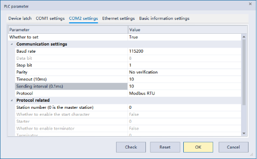
Upper computer interface settings
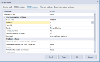
Through the PLC parameter setting in the upper computer interface, if the protocol is switched to “no protocol”, it means the user-defined protocol.
Serial port parameters mainly include baud rate, data bits and other serial port parameters.
Start/end characters can be sent when start characters are enabled. Start/end characters will be distinguished when they are received. See the instructions in the sending and receiving process for details.
It is important to note that the characters here are actually decimal values.
PORTPARA command
-[PORTPARA (s) (n)]
Content, range and data type
| Parameter | Content | Range | Data type | Data type (label) | Custom variable type |
|---|---|---|---|---|---|
| (s) | Serial port parameters to be set | 0 to 256 | Unsigned BIN16 bits | ANY16 | -- |
| (n) | Which communication port to set, 0 means COM1, 1 means COM2 | 0, 1 | Unsigned BIN16 bits | ANY16 | INT |
Device used
| Instruction | Parameter | Devices | Index modification | Pulse expansion | |||||||||||||||||||||||
|---|---|---|---|---|---|---|---|---|---|---|---|---|---|---|---|---|---|---|---|---|---|---|---|---|---|---|---|
| X | Y | M | S | SM | T(bit) | C(bit) | LC(bit) | HSC(bit) | D.b | KnX | KnY | KnM | KnS | T | C | D | R | SD | LC | HSC | K | H | E | [D] | XXP | ||
| PROTOCOL | Parameter 1 | ● | ● | ● | ● | ● | ● | ● | ● | ● | ● | ● | ● | ||||||||||||||
| Parameter 2 | ● | ● | ● | ● | ● | ● | ● | ● | ● | ● | ● | ● | |||||||||||||||
Function
It is used to set the communication protocol at the time of RUN, and the above command is actually used to set a specific value for the parameter modification sign.
●The specific calculation formula is: (parameter setting value + offset of the corresponding serial port's initial special device + 10)*2
For example, setting the protocol to Modbus RTU master station (H20), i.e. (0x20 +2593-2590 +10) * 2, which is (32 +3 +10) *2=90, which mainly aims to avoid random modification of serial port parameters during operation.
For user-defined protocol, if the set parameters are triggered, the value will be changed only after the command is completely completed.
For Modbus master station protocol, if the set parameters are triggered, the value will be changed only after the command is completely completed.
For Modbus slave station protocol, if the set parameters are triggered, switching can be performed when the received data is not being processed.
For details, please refer to “PROTOCOL Instruction Description”.
Priority description of serial port parameters
The priority of serial port parameter setting is listed below. At present, serial port parameters are saved at the time of power failure.
Serial port parameter setting command setting = using ladder diagram MOV command to set corresponding SD device > upper computer downloading parameters > previous data saved at the time of power outage.
Basic ladder diagram

Setting serial port parameters:
Baud rate: 115200, stop bit: 1, data bit: 8, parity
Set the protocol to a user-defined protocol
Sending interval: 5ms
Reception timeout: 100ms
Retries: 3 times
Character interval timeout: 30ms
Sending starting address D200 of user-defined protocol: sending length 8
Directly trigger sending upon being
After receiving, directly close the command and reset the command receiving sign.
1.Sending and receiving mechanism
(1)No start character (STX) and end character (ETX)
16-bit (SM2594 is OFF)
Devices will be divided into high and low directly and then the data in the low address will be sent first, followed by the data in the high address.

For instance, the sent data are 01, 02, 03, 04 and 05
When X1 is ON, the sent and received data of communication are stored as follows after the command is executed.
For instance, the received data are 11, 12, 13 and 14
8-bit (SM2594 is ON)
Get the value of the low address of the device directly and send it

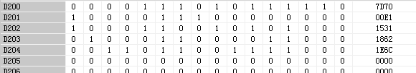
As shown in above ladder diagram and under above data transmission, the sent data should be: 70 E1 31 62 6C.
The received data will also be stored at low address.
(2)Opening and setting the start character STX
The value of the start character SD2600 is valid only when it is at low bit.
When STX is opened, the data will start with the start character STX at the time of sending, and the data starting with STX will be received, but no STX will be shown.
When the data starting with STX is received in the half way,the reception process will restart.
If the first character is not received, it will be judged as time out in case of the timeout of the first character; if the first character is received, no matter what kind of data is received, the character timeout will be counted since the last character is received.
As shown in above ladder diagram and under above data transmission, the sent data should be FE 70 7D E1 00 31.
If FE 51 26 34 15 is sent to PLC, the following data will be received.
If FE 25 63 FE 51 26 34 15 is sent to PLC, the following data will be received.

2.Opening and setting the end character ETX
The value of the end character SD2601 is valid only when it is at low bit.
When ETX is opened, the data will end with ETX at the end of sending.
SM2610 and SM2593 are immediately ON when an ETX is received, no matter whether sufficient length of data is received.
As shown in above ladder diagram and under above data transmission, the result is 70 7D E1 00 31 FD.
As shown in above ladder diagram, if 01 06 FD is sent, the following data will be received. If FD is sent directly, it will be judged as “end” directly.
Both start character (STX) and end character (ETX) are opened
When both start character and end character are opened, it is generally deemed as the combination of above single open state.
However, if only ETX data is received when both characters are opened, it will not end immediately, but it will change to judge the character interval time, without starting to receive data.
Receiving after sending (similar to Modbus master station mechanism)
1. OFF (default) state of sending control switch (SM2590) and receiving control switch (SM2592)
When the contact point of RS command is set ON, SM2591 will be sent immediately when it is set ON, and SM2591 will be automatically set OFF after sending.
After sending, judge the state of SM2593. If it is ON, it will stop in this command all the time and wait until it is set OFF and then receive data; if it is OFF, it will start receiving data.
After the first character timeout time (SD2597), if no character is received, it is judged as timeout; if retry time is set, retry it. If the communication cannot be achieved after retry, an error will be reported and SM2593 and SM2614 are set to be on.
After receiving the first character, judge whether the interval between characters exceeds the time set by SD2599, otherwise an error will be reported. (Please refer to “Character Interval Timeout” for details.)
If there are two or more commands, after SM2591 is set to be ON, RS command for setting the first ON will be sent, and then if this RS command is completed* 1and set to be ON, SM2591 will switch to the next RS command in the ladder diagram sequence* 2.
If there are two or more commands, another data will be sent when the data is half received, and the original command is continued to be executed for receiving until it is completed.
2.Sending mode when the sending control switch (SM2590) is ON
When the sending control switch (SM2590) is ON, there is no need to control SM2591 to be set as ON.
At this time, as long as the contact of RS command is triggered, it can be sent, and SM2591 is automatically set as ON.
3.Receiving mode when the receiving control switch (SM2592) is ON
When the receiving control switch (SM2592) is ON, SM2593 is automatically turned to OFF when the command is executed.
When receiving, the status of SM2593 will not be judged again, and SM2593 will still be set as ON after receiving.
4.ON state of sending control switch (SM2590) and receiving control switch (SM2592)
Under above circumstance, the data can be sent only by triggering the contact in front of the RS command, which will automatically turn to the waiting for receiving state, and when the reception is completed, it will turn to the next opened RS command.
(3)Send only

When the sending length is set to a non-0 value, the receiving length is set to 0. This is send-only mode.
1.OFF state of sending control switch (SM2590)
When SM2591 is set as ON, it sends data and does not receive data.
If there are two or more commands, after SM2591 is set to be ON, RS command for setting the first ON will be sent, and then if this RS command is completed and set to be ON, SM2591 will switch to the next RS command in the ladder diagram.
2.ON state of sending control switch (SM2590)
The data will be sent when RS command is triggered.
When several commands are triggered, the data will be set in circular manner, and during the circular sending, the data will be sent at intervals according to the set sending intervals.
(4)Receive-only

When the sending length is set to a non-0 value, the receiving length is set to 0. This is send-only mode.
1.OFF state of sending control switch (SM2590)
When SM2591 is set as ON, it sends data and does not receive data.
If there are two or more commands, after SM2591 is set to be ON, RS command for setting the first ON will be sent, and then if this RS command is completed and set to be ON, SM2591 will switch to the next RS command in the ladder diagram.
2.ON state of sending control switch (SM2590)
The data will be sent when RS command is triggered.
When several commands are triggered, the data will be set in circular manner, and during the circular sending, the data will be sent at intervals according to the set sending intervals.
(5)Sending after receiving by the receive-only and send-only mode (similar to Modbus slave station mechanism)

Receive-only: when it is judged as completing reception, the command to be triggered will be judged according to the received contents; meanwhile, the received data will be saved.
Send-only: the sent contents are different after M2 is triggered and M3 is triggered. After the trigger is over, they will return to trigger the receive-only part of M1.
A. 9.5.1.4 Error information
The current error code will be displayed in theSD7, SD0 and SD2611 and SD2612.
The error codes that will occur in user-defined protocols are mainly shown as follows:
| Error code | Content |
|---|---|
| 3181H | Data reception timeout |
| 3188H | Length error |
| 3189H | COM2 data error. “Check whether the parameters of the command are wrong. Check whether the set value is supported by the slave station. (Please refer to Modbus exception 03).” |
| 318EH | At present, COM2 does not support this command or function. When the slave protocol is set, the communication commands related to master station or master station functions cannot be used. Please change the protocol or close the contact before the corresponding command or close the corresponding communication function. |
| 318FH | COM2 sending timeout. If this error message appears, please contact technical personnel. |
| 3190H | COM2 receives data beyond the cache limit. |
After resetting the protocol or communication parameters, the reported errors will be cleared.
In addition, in case of communication completion/communication error/communication timeout, the sign bit will be set after executing the command.
B.9.5.1.5 Difference with Mitsubishi
Currently known difference:
⑴ For STX and ETX, Mitsubishi can set a maximum of 4 bytes, but we only have one byte.
⑵Support accumulation, parity, CR and LF.
⑶Mitsubishi's command control is to execute the command on a fixed basis when the command is triggered first. It will not be switched to other commands midway unless the contact of this command is closed.
Modbus Protocol Description
 Introduction
The current Modbus master station protocol is generally similar to LX3V. The address is modified in the slave station part.
Basic Configuration
(1) Instruction
The RS command itself is used in the same way as the previous RS command at 3V. R device can be used.
-[RS (s) (m) (d) (n)]
Content, range and data type
| Parameter | Content | Range | Data type | Data type (label) |
|---|---|---|---|---|
| (s) | The high byte stores the station number of slave station, and the low byte stores the function code of Modbus. | - | Unsigned BIN16 bits | ANY16 |
| (m) | Slave station address. The address provided by the slave station will read or write data from the address of slave station. | - | Unsigned BIN16 bits | ANY16 |
| (d) | Length: the length read or written by Modbus. The unit is determined by function code. | - | Unsigned BIN16 bits | ANY16 |
| (n) | The starting address for data to be read or written. | - | Unsigned BIN16 bits | ANY16 |
Device used
| Instruction | Parameter | Devices | Index modification | Pulse expansion | |||||||||||||||||||||||
|---|---|---|---|---|---|---|---|---|---|---|---|---|---|---|---|---|---|---|---|---|---|---|---|---|---|---|---|
| X | Y | M | S | SM | T(bit) | C(bit) | LC(bit) | HSC(bit) | D.b | KnX | KnY | KnM | KnS | T | C | D | R | SD | LC | HSC | K | H | E | [D] | XXP | ||
| RS | Parameter 1 | ● | ● | ● | ● | ● | ● | ||||||||||||||||||||
| Parameter 2 | ● | ● | ● | ● | ● | ● | |||||||||||||||||||||
| Parameter 3 | ● | ● | ● | ● | ● | ● | |||||||||||||||||||||
| Parameter 4 | ● | ● | ● | ● | |||||||||||||||||||||||
(2) Special device setting
Special address table
| COM1 special D device (SD) | |
|---|---|
| 2540 | Communication port settings |
| 2541 | COM1 serial port parameter modification sign |
| 2542 | |
| 2543 | |
| 2544 | Station number settings |
| 2545 | Station number modification sign |
| COM2 special D device (SD) | COM2 special M device (SM) | ||
|---|---|---|---|
| 2590 | Communication port settings | 2590 | Sending control on |
| 2591 | COM1 serial port parameter modification sign | 2591 | Send control/send prompt |
| 2592 | Protocol settings | 2592 | Reception control on |
| 2593 | Protocol modification sign | 2593 | Accept control/receive prompt |
| 2594 | Station number settings | 2594 | 8-bit mode (for user-defined protocol) |
| 2595 | Station number modification sign | 2595 | |
| 2596 | Sending interval (0.1ms) 0-32767 Set 0 to 10 (1ms) | 2596 | |
| 2597 | Communication timeout setting (10ms) 0-32767 Set 0 to 10 (100ms) | 2597 | |
| 2598 | Timeout retry times 0-32767 | 2598 | |
| 2599 | Character interval timeout setting (for custom protocol) (0.1ms) 0 to 32767 Set 0 to 10 (1ms) | 2599 | |
| 2600 | STX value | 2600 | |
| 2601 | ETX value | 2601 | |
| ... | .. | ||
| 2610 | Volume of data received | 2610 | Communication completion sign |
| 2611 | Last error | 2611 | Receiving sign |
| 2612 | Current error | 2612 | Retry |
| 2613 | Error steps | 2613 | Communication error |
| 2614 | Error station number | 2614 | Communication timeout |
| 2615 | Cumulative error times | 2615 | |
The contents that will be used or set by the Modbus protocol have been marked with “underline” and “in bold”.
In addition, the devices to be used as judgment conditions have been marked “in bold” in the table.
1.Communication port settings SD2590
| Bit number | Name | Content | |
|---|---|---|---|
| 0 (bit OFF) | 1 (bit ON) | ||
| b0 | Data length | 7 digits | 8 digits |
b1 b2 | Parity check | b2, b1 (0, 0): None (0,1): Odd parity (ODD) (1,1): Even parity (EVEN) | |
| b3 | Stop bit | 1 bit | 2 bit |
b4 b5 b6 b7 b8 b9 | Baud rate (bps) | .b9,b8,b7,b6,b5,b4 ( 0, 0, 0, 1, 1, 1): 4800 ( 0, 0, 1, 0, 0, 0): 9600 ( 0, 0, 1, 0, 0, 1): 19200 ( 0, 0, 1, 0, 1, 0): 38400 ( 0, 0, 1, 0, 1, 1): 57600 | .b9,b8,b7,b6,b5,b4 ( 0, 0, 1, 1, 0, 0): 115200 ( 0, 0, 1, 1, 0, 1): 187500 ( 0, 0, 1, 1, 1, 0): 230400 ( 0, 0, 1, 1, 1, 1): 460800 ( 0, 1, 0, 0, 0, 0): 921600 |
According to the bit setting provided in the above table, the serial port parameter is set to SD2590.
At present, the setting is basically the same as 3V. As a higher baud rate can be set, the bits used for enabling STX and ETX need to be moved back by two bits.
For instance, set serial port parameters: baud rate: 115200, stop bit: 1, data bit: 8, parity bit: none.
Then set the value HC1 (K1217) on SD2590.
At present, the parameters directly set to SD2590 are only valid in the first cycle of PLC RUN.
If the parameters need to be modified during RUN, they can be set by PORTPARAM command.
2.Protocol settings SD2592
| Protocol settings | |||
|---|---|---|---|
| 0H | Wecon Modbus slave station | 10H | User-defined protocol |
| 2H | Modbus RTU slave station | 20H | Modbus RTU master station |
| 3H | Modbus ASCII slave station | 30H | Modbus ASCII master station |
The corresponding protocol can be set by setting the corresponding value in SD2592.
At present, the parameters directly set to SD2590 are only valid in the first cycle of PLC RUN.
If the parameters need to be modified during RUN, they can be set by PROTOCOL command.
At present, COM1 cannot support the protocol other than W Modbus slave protocol.
3.Sending interval SD2596
The main function of sending interval is: to determine how long does it take to wait to send the next command when one command is completed. When 0 is set, it will not wait for sending at specified interval, but it will be affected by scanning period.
The unit of transmission interval is 0.1 ms, i.e. the interval time is 10ms when the value is set to be 100.
4.Communication timeout SD2597 and timeout retry SD2598
The main function of communication timeout is: to determine when the retry is required or an error needs to be reported when the data is not received after being sent by PLC. When 0 is set, it is 100ms by default.
The unit of transmission interval is 10ms, i.e. the timeout judgment time is 100ms when the value is set to be 10.
When receiving timeout occurs, it will judge whether there are retries and the current retry times. If the retry times are greater than or equal to SD2598, an error will be reported.
If SD2598 is set to 0, no retry is required.
When it is set to 1, send the data once and then send it again after timeout.
(3) Serial port parameter setting
1.PORTPARA command
-[PORTPARA (s) (n)]
Content, range and data type
| Parameter | Content | Range | Data type | Data type (label) | Custom variable type |
| (s) | Serial port parameters to be set 0~256 | - | Unsigned BIN16 bits | ANY16 | INT |
| (n) | Which communication port to be set, 0 means COM1, 1 means COM2 | -2147483648~ 2147483647 | Unsigned BIN16 bits | ANY16 | INT |
Device used
| Instruction | Parameter | Devices | Index modification | Pulse expansion | |||||||||||||||||||||||
|---|---|---|---|---|---|---|---|---|---|---|---|---|---|---|---|---|---|---|---|---|---|---|---|---|---|---|---|
| X | Y | M | S | SM | T(bit) | C(bit) | LC(bit) | HSC(bit) | D.b | KnX | KnY | KnM | KnS | T | C | D | R | SD | LC | HSC | K | H | E | [D] | XXP | ||
| PORTPARA | Parameter 1 | ● | ● | ● | ● | ● | ● | ● | ● | ● | ● | ● | ● | ||||||||||||||
| Parameter 2 | ● | ● | ● | ● | ● | ● | ● | ● | ● | ● | ● | ● | |||||||||||||||
Function
Used to set communication parameters at the time of RUN.
For details, please refer to “PORTPARA Instruction Description”.
2.PROTOCOL command
-[PROTOCOL (s) (n)]
Content, range and data type
| Parameter | Content | Range | Data type | Data type (label) | Custom variable type |
|---|---|---|---|---|---|
| (s) | Protocol number to be set | 0 to 65535 | Unsigned BIN16 bits | ANY16 | INT |
| (n) | Which communication port to be set, 0 means COM1, 1 means COM2 | 1 | Unsigned BIN16 bits | ANY16 | INT |
Device used
| Instruction | Parameter | Devices | Index modification | Pulse expansion | |||||||||||||||||||||||
|---|---|---|---|---|---|---|---|---|---|---|---|---|---|---|---|---|---|---|---|---|---|---|---|---|---|---|---|
| X | Y | M | S | SM | T(bit) | C(bit) | LC(bit) | HSC(bit) | D.b | KnX | KnY | KnM | KnS | T | C | D | R | SD | LC | HSC | K | H | E | [D] | XXP | ||
| PROTOCOL | Parameter 1 | ● | ● | ● | ● | ● | ● | ● | ● | ● | ● | ● | ● | ||||||||||||||
| Parameter 2 | ● | ● | ● | ● | ● | ● | ● | ● | ● | ● | ● | ● | |||||||||||||||
Function
It is used to set the communication protocol at the time of RUN, and the above command is actually used to set a specific value for the parameter modification sign.
The specific calculation formula is: (parameter setting value + offset of the corresponding serial port's initial special device + 10)*2
For example, setting the protocol to Modbus RTU master station (H20), i.e. (0x20 +2593-2590 +10) * 2, which is (32 +3 +10) *2=90, which mainly aims to avoid random modification of serial port parameters during operation.
For Modbus master station protocol, if the set parameters are triggered, the value will be changed only after the command is completely completed.
For Modbus slave station protocol, if the set parameters are triggered, switching can be performed when the received data is not being processed.
For details, please refer to “PROTOCOL Instruction Description”.
3.Upper computer settings
The PLC parameter setting of the upper computer can set the corresponding serial port parameters.
Specific protocol station number cannot be 0
Station number under Modbus RTU and Modbus ASCII protocol is 0: Protocol sets the master station.
Station number under Modbus RTU and Modbus ASCII protocol is non-0: Protocol sets the slave station.
Serial port parameters are filled in according to the contents in the table.
Note: RTU protocol cannot set 7-bit data bits.
4.Priority description of serial port parameters
The priority of serial port parameter settings is listed below.
At present, serial port parameters are saved at the time of power failure.
Serial port parameter setting command setting = using ladder diagram MOV command to set corresponding SD device > upper computer downloading parameters > previous data saved at the time of power outage.
(4) Basic ladder diagram

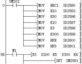
Serial port parameter setting
Baud rate: 115200, data bit: 8, parity bit: none, stop bit: 1
Communication protocol setting: ModbusRTU master station protocol
Sending interval: 5ms
Reception timeout: 100ms
Timeout retry times: 3 times
Station number 01H, function code 03H, slave station address 10, length 05
1.Sending and receiving process
Modbus master station
When programming, in front of each RS (Modbus mode) command, each operand unit should be assigned with a certain value according to the address of the communication operation object, operation type, operation register address, data number, sending or receiving unit. Once the execution starts, the system program will automatically calculate CRC parity, organize communication frames, and complete the operation of sending data and receiving response.
If Modbus-ASC protocol is used for communication (SD2592 is set to H30), the HEX-ASC format for sending and receiving data is automatically changed by PLC system program, and the method of using RS (Modbus mode) command by users is exactly the same as that of using Modbus-RTU protocol.
In the plc program, if multiple RS (Modbus Mode) commands are driven, when the system program is executed, the next RS command will be processed in the same way after the links of “sending, waiting for response, receiving, checking, analyzing and storing" of one RS command are completed, until all RS commands are executed and started again. Users don't need to care about the timing and process of its execution, which simplifies PLC programming design. This is the advantage of Modbus command.
List of Modbus Master Station Function
| Function code | Function name | Details |
|---|---|---|
| 0x01 | Coil state readout | Coil state readout (several points) |
| 0x02 | Input readout | Input readout (several) |
| 0x03 | Holding register readout | Holding register readout (several points) |
| 0x04 | Input register readout | Input register readout (several points) |
| 0x05 | 1 Coil written | Coil written (only one point) |
| 0x06 | 1 Register written | Holding register written (only one point) |
| 0x0F | Batch coil written | Multi-point coil written |
| 0x10 | Batch register written | Multi-point holding register written |
 For instance:
 Serial port parameter setting
Baud rate: 115200, data bit: 8, parity bit: none, stop bit: 1
Communication protocol setting: ModbusRTU master station protocol
Sending interval: 5ms
Reception timeout: 100ms
Timeout retry times: 3 times
Station number 01H, function code 03H, slave station
As shown in above ladder diagram:
When M1 is turned ON, PLC will send data (hexadecimal) from COM2 of PLC: 01 03 00 0A 00 05 A5 C8
01: represents slave address, the high 8 bits of (s);
03: Modbus command code, the low 8 bits of (s), which means to read the slave register;
00 0A: the address of slave register to be read, the value of (m);
00 05: The number of registers to be read, the value of (d),
A5 C8: CRC parity code
2.Modbus slave station
When plc is used as Modbus slave station, it supports communication operation commands such as 0x01, 0x03, 0x05, 0x06, 0x0f and 0x10 of Modbus; through these commands, the coils that can read and write PLC have variables such as M, S, T, C, X (read-only) SM, Y, LC, HSC, etc. Register variables include D, T, C, R, SD, LC and HSC.
When the Modbus communication host accesses (reads or rewrites) the internal variables of PLC slave, it must follow the following definition of communication command frame and variable address index method, so as to carry out normal communication operation.
①Instruction code 0x01 (01): read coil
| No. | Data (byte) meaning | Number of bytes | Description |
|---|---|---|---|
| 1 | Slave address | 1 byte | Take value 1~247, which is set by SD2544 and SD2594 |
| 2 | 0x01 (command code) | 1 byte | Read coil |
| 3 | Start address of coil | 2 bytes | High bit in the front and low bit in the rear, see the addressing of the coil |
| 4 | Coil number | 2 bytes | High bit in the front and low bit in the rear (N) |
| 5 | CRC parity | 2 bytes | High bit in the front and low bit in the rear |
Response frame format: slave address + 0x01 + bytes + coil status + CRC parity
| No. | Data (byte) meaning | Number of bytes | Description |
|---|---|---|---|
| 1 | Slave address | 1 byte | Take value 1~247, which is set by SD2544 and SD2594 |
| 2 | 0x01 (command code) | 1 byte | Read coil |
| 3 | Number of bytes | 1 byte | Value: [(N+7)/8] |
| 4 | Coil state | [(N+7)/8] bytes | Every 8 coils are combined into one byte. If the last coil is less than 8 bits, the undefined part is filled with 0. The first 8 coils are in the first byte, and the coil with the smallest address is in the lowest bit. And so forth. |
| 5 | CRC parity | 2 bytes | High bit in the front and low bit in the rear |
Error response: see error response frame
② Instruction code 0x03 (03): read register
Request frame format: slave address+ 0x03 + register start address + register number + CRC parity.
| No. | Data (byte) meaning | Number of bytes | Description |
|---|---|---|---|
| 1 | Slave address | 1 byte | Take value 1~247, which is set by SD2544 and SD2594 |
| 2 | 0x03 (command code) | 1 byte | Read register |
| 3 | Register start address | 2 bytes | High bit in the front and low bit in the rear, see the addressing of the register |
| 4 | Register number | 2 bytes | High bit in the front and low bit in the rear (N) |
| 5 | CRC parity | 2 bytes | High bit in the front and low bit in the rear |
| No. | Data (byte) meaning | Number of bytes | Description |
|---|---|---|---|
| 1 | Slave address | 1 byte | Take value 1~247, which is set by SD2544 and SD2594 |
| 2 | 0x03 (command code) | 1 byte | Read register |
| 3 | Number of bytes | 1 byte | Value: N*2 |
| 4 | Register value | N*2 bytes | Every two bytes represents a register value, with high bit in the front and low bit in the rear. Register with small address comes first |
| 5 | CRC parity | 2 bytes | High bit in the front and low bit in the rear |
Response frame format: slave address+0x03+bytes+register value +CRC parity.
Error response: see error response frame
③ Instruction code 0x05 (05): write single coil
Response frame format: slave address + 0x05+ bytes + coil address + CRC parity
| No. | Data (byte) meaning | Number of bytes | Description |
|---|---|---|---|
| 1 | Slave address | 1 byte | Take value 1~247, which is set by SD2544 and SD2594 |
| 2 | 0x05 (command code) | 1 byte | Write single coil |
| 3 | Coil address | 2 bytes | High bit in the front and low bit in the rear, see the addressing of the coil |
| 4 | Coil state | 2 bytes | High bit in the front and low bit in the rear. If the value is not 0, it is valid. |
| 5 | CRC parity | 2 bytes | High bit in the front and low bit in the rear |
Response frame format: slave address+0x05+coil address+ coil state+ CRC parity.
| No. | Data (byte) meaning | Number of bytes | Description |
|---|---|---|---|
| 1 | Slave address | 1 byte | Take value 1~247, which is set by SD2544 and SD2594. |
| 2 | 0x05 (command code) | 1 byte | Write single coil |
| 3 | Coil address | 2 bytes | High bit in the front and low bit in the rear, see the addressing of the coil |
| 4 | Coil state | 2 bytes | High bit in the front and low bit in the rear. If the value is not 0, it is valid. |
| 5 | CRC parity | 2 bytes | High bit in the front and low bit in the rear |
Error response: see error response frame
Wherein the coil state 0xFF00 means being set as ON and 0x0000 means being set as OFF.
④ Instruction code 0x06 (06): write single register
Request frame format: slave address+ 0x06 + register address + register value + CRC parity.
| No. | Data (byte) meaning | Number of bytes | Description |
|---|---|---|---|
| 1 | Slave address | 1 byte | Take value 1~247, which is set by SD2544 and SD2594 |
| 2 | 0x06 (command code) | 1 byte | Write single register |
| 3 | Register address | 2 bytes | High bit in the front and low bit in the rear, see the addressing of the register |
| 4 | Register value | 2 bytes | High bit in the front and low bit in the rear. If the value is not 0, it is valid. |
| 5 | CRC parity | 2 bytes | High bit in the front and low bit in the rear |
Response frame format: slave address+0x06+register address+ register value+ CRC parity.
| No. | Data (byte) meaning | Number of bytes | Description |
|---|---|---|---|
| 1 | Slave address | 1 byte | Take value 1~247, which is set by SD2544 and SD2594 |
| 2 | 0x06 (command code) | 1 byte | Write single register |
| 3 | Register address | 2 bytes | High bit in the front and low bit in the rear, see the addressing of the register |
| 4 | Register value | 2 bytes | High bit in the front and low bit in the rear. If the value is not 0, it is valid. |
| 5 | CRC parity | 2 bytes | High bit in the front and low bit in the rear |
Error response: see error response frame.
⑤ Instruction code 0x0f (15): write multiple coils
Request frame format: slave address + 0x 0f+ coil start address + coil number+ number of bytes+ coil state+ CRC parity.
| No. | Data (byte) meaning | Number of bytes | Description |
|---|---|---|---|
| 1 | Slave address | 1 byte | Take value 1~247, which is set by SD2544 and SD2594 |
| 2 | 0x 0f (command code) | 1 byte | Write multiple coils |
| 3 | Start address of coil | 2 bytes | High bit in the front and low bit in the rear, see the addressing of the coil |
| 4 | Coil number | 2 bytes | High bit in the front and low bit in the rear. N, maximum value: 1968 |
| 5 | Number of bytes | 1 byte | Value: [(N+7)/8] |
| 6 | Coil state | [(N+7)/8] bytes | Every 8 coils are combined into one byte. If the last coil is less than 8 bits, the undefined part is filled with 0. The first 8 coils are in the first byte, and the coil with the smallest address is in the lowest bit. And so forth. |
| 7 | CRC parity | 2 bytes | High bit in the front and low bit in the rear |
Response frame format: slave address+ 0x 0f +coil start address+ coil number+ CRC parity
| No. | Data (byte) meaning | Number of bytes | Description |
|---|---|---|---|
| 1 | Slave address | 1 byte | Take value 1~247, which is set by SD2544 and SD2594 |
| 2 | 0x 0f (command code) | 1 byte | Write multiple coils |
| 3 | Start address of coil | 2 bytes | High bit in the front and low bit in the rear, see the addressing of the coil |
| 4 | Coil number | 2 bytes | High bit in the front and low bit in the rear. |
| 5 | CRC parity | 2 bytes | High bit in the front and low bit in the rear |
Error response: see error response frame
⑥ Instruction code 0x10 (16): write multiple registers
Request frame format: slave address+ 0x10 + register start address + register number +number of bytes+ register value+ CRC parity.
| No. | Data (byte) meaning | Number of bytes | Description |
|---|---|---|---|
| 1 | Slave address | 1 byte | Take value 1~247, which is set by SD2544 and SD2594 |
| 2 | 0x10 (command code) | 1 byte | Write multiple registers |
| 3 | Register start address | 2 bytes | High bit in the front and low bit in the rear, see the addressing of the register |
| 4 | Register number | 2 bytes | High bit in the front and low bit in the rear. N, maximum value: 120 |
| 5 | Number of bytes | 1 byte | Value: N*2 |
| 6 | Register value | N*2 (N*4) | |
| 7 | CRC parity | 2 bytes | High bit in the front and low bit in the rear |
Response frame format: slave address+0x10+ register start address+ register number + CRC parity.
| No. | Data (byte) meaning | Number of bytes | Description |
|---|---|---|---|
| 1 | Slave address | 1 byte | Take value 1~247, which is set by SD2544 and SD2594 |
| 2 | 0x10 (command code) | 1 byte | Write multiple registers |
| 3 | Register start address | 2 bytes | High bit in the front and low bit in the rear, see the addressing of the register |
| 4 | Register number | 2 bytes | High bit in the front and low bit in the rear. N, maximum value: 120 |
| 5 | CRC parity | 2 bytes | High bit in the front and low bit in the rear |
Error response: see error response frame
⑦ Error response frame
Error response: slave address + (command code + 0x80) + error code + CRC parity.
| No. | Data (byte) meaning | Number of bytes | Description |
|---|---|---|---|
| 1 | Slave address | 1 byte | Take value 1~247, which is set by SD2544 and SD2594 |
| 2 | Instruction code+0x80 | 1 byte | Error command code |
| 3 | Error code | 1 byte | 1 to 4 |
| 4 | CRC parity | 2 bytes | High bit in the front and low bit in the rear |
| No. | Error code | Description |
|---|---|---|
| 1 | 01 | Not supported function codes |
| 2 | 02 | Wrong address or function code |
| 3 | 03 | Wrong length |
| 4 | 04 | Incomplete command |
| 5 | 05 | Address not allowed |
⑧Slave station address table
| Word address | ||||
|---|---|---|---|---|
| Address type | Occupation | Address range | Decimal address | Total reserved address size |
| T0 to T511 | 512 WORD | 0x0000 to 0x01ff | 0 | 1536 |
| C0~C255 | 256 WORD | 0x0600 to 0x06ff | 1536 | 1024 |
| LC0 to LC255 | 512 WORD | 0x0A000 to 0x0BFF | 2560 | 1024 |
| HSC0 to HSC15 | 128 WORD | 0x0E00 to 0x0E1F | 3584 | 512 |
| D0~D7999 | 8000 WORD | 0x1000 to 0x2F3F | 4096 | 16384 |
| SD0 to SD4095 | 4096 WORD | 0x5000 to 0x5FFF | 20480 | 12288 |
| R0~R30000 | 30000 WORD | 0x8000 to 0xF52F | 32768 | 30000 |
| Bit address | ||||
|---|---|---|---|---|
| Address type | Occupation | Address range | Decimal address | Total reserved address size |
| T0 to T511 | 512 bit | 0x0000 to 0x01ff | 0 | 1536 |
| C0~C255 | 256 bit- | 0x0600 to 0x06ff | 1536 | 1024 |
| LC0 to LC255 | 256 bit- | 0x0A00 to 0x0AFF | 2560 | 1024 |
| HSC0 to HSC15 | 64 bit | 0x0E00 to 0x0E0F | 3584 | 512 |
| M0 to M8000 | 8192 bit | 0x1000 to 0x2F3F | 4096 | 16384 |
| SM0~SM4095 | 4096 bit | 0x5000 to 0x5FFF | 20480 | 12288 |
| Reserved | 0x8000 to 0xBFFF | 16383 | ||
| S0 to S4095 | 4096 bit | 0xC000 to 0xCFFF | 49152 | 8192 |
| X0 to X1023 | 1024 bit- | 0xE000 to 0xE3FF | 57344 | 4096 |
| Y0~Y1023 | 1024 bit- | 0xF000 to 0xF3FF | 61440 | 4096 |
Error information
The current error code will be displayed in the SD7, SD0, SD2611 and SD2612.
The error codes that will occur in Modbus protocols are mainly shown as follows:
| Error code | Content |
|---|---|
| 4085H | (s), (m), (d) and (n) read address exceeds the range of the device (this error is displayed in SD7 and SD0 only). |
| 3180H | COM2 data reception error. There may be interference on the communication cable, it is recommended to connect GND. |
| 3181H | COM2 data reception timeout. Check the wiring, whether the serial port parameter settings correspond to master and slave, and whether there is interference. Check whether it is caused by the late response from slave station. It is recommended to increase the sending interval SD2546. |
| 3182H | COM2 CRC parity error. There may be interference on the communication cable, it is recommended to connect GND. |
| 3183H | COM2 LRC parity error. There may be interference on the communication cable, it is recommended to connect GND. |
| 3184H | The COM2 station number is incorrectly configured. Check the slave station number setting, and check whether there is any problem with the receiving and sending mechanism from slave station. |
| 3185H | COM2 send buffer overflow If this error message appears, please contact technical personnel. |
| 3186H | COM2 function code is wrong. Check whether the set function code is a function code supported by PLC. |
| 3187H | COM2 address is wrong. Check whether the slave station has this address. (Please refer to Modbus exception 02). |
| 3188H | The length of COM2 is wrong. Check whether the communication length exceeds the length range specified by Modbus protocol or user-defined protocol. |
| 3189H | COM2 data error. Check whether parameters of the command are wrong. Check whether the set value is supported by the slave station. (Please refer to Modbus exception 03). |
| 318AH | COM2 slave station is busy. Message returned from slave station: Slave station is busy. (Please refer to Modbus exception 06). |
| 318BH | COM2 slave station does not support function codes. Check whether this function code is supported by the slave station. (Please refer to Modbus exception 01). |
| 318CH | COM2 slave station is faulty. Message returned from slave station: Slave station failed, please check whether slave station failed. (Please refer to Modbus exception 04). |
| 318DH | COM2 slave station confirmation. Message returned from slave station: slave station confirmation. (Please refer to Modbus exception 05). |
| 318EH | At present, COM2 does not support this command or function. When the slave protocol is set, the communication commands related to master station or master station functions cannot be used. Please change the protocol or close the contact before the corresponding command or close the corresponding communication function. |
| 318FH | COM2 sending timeout. If this error message appears, please contact technical personnel. |
| 3190H | COM2 receives data beyond the cache limit. |
| 31A0H | No available gateway for COM2 Message returned from the slave station: no available gateway. (Please refer to Modbus exception 0A). |
| 31A1H | COM2 indicates that no response was obtained from the target device. Message returned from the slave station: The device is not networked. (Please refer to Modbus Exception 0B). |
After resetting the protocol or communication parameters, the reported errors will be cleared.
In addition, in case of communication completion/communication error/communication timeout, the sign bit will be set after executing the command.
WECON Modbus Protocol Description
At present, WECON Modbus protocol description (special protocol) is modified based on Modbus RTU protocol.
Therefore, 7-bit data bits cannot be used in serial port parameters.
This protocol is fully compatible with Modbus RTU protocol, and the address is the same as the default address of Modbus RTU protocol of LX6V PLC.
The extended function is mainly used to communicate with PLC Editor 2.