05 Objects
This chapter provides information about objects and a description of how to configure objects.
Button/Switch
Different button has different function.Such as: Bit Switch; Bit lamp; Word Switch; Word lamp; Function Switch; Keypad Switch; Combination Switch.
Bit switch
Bit switch is designed to access the bit-address of the PLC/HMI. When bit switch is triggered, the changing of "Write Address" depends on the mode setting. When "Read" option is selected, the "Read Address" is editable.
General
To operate, monitor and display the specified PLC or HMI bit address. When the bit switch is pressed, the bit value of the operation address changes as described by the switch type. When Monitor is available, the state displayed by the bit switch is the state of the bit to which the monitor address is pointing.

Read-write
- Write Address: Bit address operation control for HMI or PLC.
- Read: Enable the monitoring the read address or not.
- Same read-write address: Enable it if want to the read address and write address is exactly same.
- Read Address: Monitoring address.
Mode
- Set OFF: Set off the write address.
- Set ON: Set on the write address.
- Momentary: Set on the write address when switch is pressed, and reset the address when switch is released.
- Delay: Interval for keep on the write address. For example: Assign the delay time as 500, write address will be reset after release button in 0.5 second.
- Switch: Switch between True(1) and False(0) when switch is triggered.
Display
- Inverted Display: Display the state picture and text of the object reversely.
- Quick Read: The priority of read and write is higher than any other objects on the same screen.
- Blink: Blinking while control bit is triggered;
- Blink when ON: Blink when control bit is ON.
- Blink when OFF: Blink when control bit is OFF.
Minimum hold time: Only when the time of press and hold the object is greater than the set value, the object function will be executed.
Indirect addressing:
- Read address: Use the value of the read address to determine the address A after deviation, and use the address A as the read address of the object.
For example:: HDX11.0 is the read address of the object. The three indirect read address is D0, E1, and HDW2. The system would read the value of address HDW2.
If its value is 22, and the second indirect read address E1 would update to E23, then the system would read the value of E23.
If its value is 33, then the first indirect read address D0 would update to D33, then the value of D33 is 44, that is, the bit of deviation is 44 bits.
A word has 16 bits, divide 16 into 44, and the answer is 2, remainder 12. Therefore, the read address of object is update from HDX11.0 to HDX13.12, and the final read address is HDX13.12.
Write address: It is the same as the read address.
Text

All languages: Edit the texts of all the languages of the object in a time. A maximum of 8 languages are supported.

All states: Edit the texts of all the states of the object in a time.
Font: Set the font of the text after selecting the state. The number of the characters input is displayed.
Copy attribute to states: Set the color of font after selecting state and text, and click "Copy attribute to states", then they would be in the same color.
Copy text: Click it and the texts of all the objects would be the same.
Copy style: Click it and the styles of all the objects would be the same.
Graphic

Bitmap: You could design beautiful scenes with bitmap. Static diagram and bitmap with states are supported.
Vectogram: Use to figure SVG vector diagram is concise and lively geometry, generally shows the various industrial field, with the performance of the more abundant than bitmap method, and the vector diagram drawing will not be needed or scaling distortion.
Security

Object lock
- Lock address: Using interlock address, address 0 means that the object would be locked and display a lock icon. Only when the interlock-bit address points to 1 will the bit switch be operated.
- Hide "lock" icon: If don't want to display the icon, you may check it. will be "no show" lock "icon" tick.
- Lock when "ON": check it and the bit address will be locked when the interlock address is set to 1.
Touch available: If you check it, you could operate the object when you touch it.
Enable beep: If you check it, the object will beep when you touch it.
Extended trigger functions. It is only valid for PLC address.

No trigger: No way to trigger
Trigger before pressing: Trigger bit address is set to 1 before pressing
Trigger after pressing: After pressing Enter, trigger bit address is set to 1 before closing the keyboard
Trigger and reset before pressing: Trigger bit address is set to 1 and then set to 0 bedore pressing
Trigger and reset after pressing: After pressing Enter, trigger bit address is set to 1 and then set to 0 before closing the keyboard
Trigger before pressing, reset after: Trigger bit address is set to 1 before pressing; After pressing Enter, trigger bit address is set to 0 before closing the keyboard
Access denied setting
Users can set enable password for object. There are following operating setting when user permissions are insufficient. But "Pop login screen" and "Hide object" are mutually exclusive.
- Pop login screen
- Every time: Userlogin screen will pop-up when user permissions are insufficient;
- When change user: Userlogin screen will pop-up when user permissions, and if users logged in successfully, the previous users will log out.
- Pop once: Userlogin screen will pop-up when user permissions are insufficient, but when user enter the right password, this object can be operated by anyone.
- Hide object: When the user has no permission, the object is hidden. When the user has permission, the object is displayed and can be operated.
Animation

Data format
This format is for settings address, and it is fixed for all objects.
Proportion:
The proportional gain setting is a proportional change to the moving and scaling values. Result=Gain*original value+Offset. This function is just for display. Actual value is still the original value.
For example, the HDW1 original value is 5, Gain is 0.001, Offset is 0. The final result will be displayed as 0.005, while HDW1 actual value still is 5.
For example: If the proportional gain value is x and the moving or scaling value is y, then the actual moving or scaling value is (x*y).
Movement
The function of [Movement] is to move the position of object on the screen according to the value of address and movement type.
There are three movement type:
- X-axis movement.
- Y-axis movement.
- XY-axis movement.
For example
If the starting address of the movement is HDW10 and the movement type is [XY axis movement], HDW10 controls the X-axis movement, and HDW11 controls the Y-axis movement.
Deform
Deform object display size on screen mainly depends on width and height.
Deform type: left, right, up, down, left and right, up and down, right/left and up/down, right/left or up/down.
Address editor
The address editor is a tool used to assist in generating address strings. The address of object is composed of connection, device station number, device type and address number.

| Name | Description |
|---|---|
| PLC address/station NO. | Set the device station NO. to access. If default station NO. is selected, then the station NO. is the de The station number is the default station number for "Connection" settings in "System Parameters". |
| User input | The address is not from address library, but a string. |
| From address Library | The address is selected from address library. If there is no data in address library, it is invalid. |
| System address | Display all the items of address library. The current one is the address referenced by the object. |
| Connection | PLC that already exists in the project. |
| Address type | The address type or internal register type included in the PLC selected by the project. |
| Address NO. | To input address NO. |
| A to F and 0 to 9 | To input address NO. through mouse. |
| Clear | Clear the content of edit box of address. |
| ← | Backspace. To delete the last character of the edit box. |
| Close | Close address editor |
| OK | Close the editor and save the editing results.
|
Bit lamp
"Bit Lamp" could monitor and display the specified PLC or HMI bit address, and its state changes according to the specified address value.
Description

Address: Monitoring and display the address status.
Hide
- Inverted Display: Display reverse state of the picture and text. For example, the value of write address is on (Corresponding to state 1), while the graphic of off (Corresponding to state 0) is displayed.
- Quick Read: The priority of read and write is higher than any other objects on the same screen.
- Blink: Blink condition;
- Blink when ON: blink when read address is ON.
- Blink when OFF: blink when read address is OFF.
- Hide: Control the hide status of object via Control Bit's state. Hide object cannot be operated at all.
- Control Bit: Hide condition.
- Hide when OFF: Hide when control bit is OFF.
- Hide when ON: Hide when control bit is ON.
- Invisible: Object is always keeps hidden during project running.
Word switch
"Word Switch" could change value of specified PLC or HMI word address, when the switch is triggered the value will be written to specified address.
Description

Edit
- Read address: Read value from object display.
- Same read-write address: Enable it if want to the read address and write address is exactly same.
- Write address: Write value to specified address.
Data format
- Format: Set the data format: 16bit BCD, 16bit Unsigned, 16bit Signed, 32bit BCD, 32bit Unsigned, 32bit Signed, 32bit Float.
Mode
- Set value: Set a constant value for the word address.
- Increase: Increase Operand value for each time the switch is triggered.
- Decrease: Decrease Operand value for each time the switch is triggered.
- High/Low limit: The value will be not able to change when the value reaches limits.
Min.Hold Time:After continuously clicking the button for a period of time, the button will perform operations continuously
Word lamp
"Word Lamp" could display value of specified PLC or HMI word address, the display state of the component changes as the value of the read address changes.
Description

Address
- Read address: Read the value from object display.
- States count: Total status number for current word address, which could change the state value according to different status in button [State values], range: 1-256.
- State with value out of range: When the value of the read address is not on the range of states' value, it will cause no corresponding status number is displayed. There are two modes for process when the value is out of range.
- Hide: Hide the object when the value is out of range;
- Show state: Specify a status when the value is out of range, for example the total states is 6(range from state No.0~No.5), but the read value is 6, at this moment the object will show the state No.0 if selected item of show state is No.0;
For example
The state No.0 default fill value 0, No.1 default fill value 1... and so on.
If change settings as below figure shows
When value of read address is 11, object displays state No.1.

Transform state
- Quick Read: The priority of read and write is higher than any other objects on the same screen.
- Auto transforms: Object switch states automatically

- Trigger to transform: Trigger condition of auto transform
- Auto return: Return to the initial state after reaching the final state;
- Time of transform: Set the interval of transform between two states;
- Dynamic interval: Set the dynamic interval of transform between two states. If the value in address is 10, then the frequency of automatic switching state is 10*100ms = 1s.
Manual

- Set state: Set a constant value to address(according to the operate state selection) when click the object.
- State increase: Increase the address value by one step when click the object, the upper limit is depends on the Last state selection.
- State decrease: Decrease the address value by one step when click the object, the lower limit is depends on the Last state selection..
- Last state: The upper limit or lower limit(Final state) of state increase/decrease;
Button
Button is designed to input data into the corresponding inputbox, this object need to work with the numeric input and character input.
Description

- Control bit: This is for control operation, such as "Enter", "Delete", "Clear", "Esc and so on.
- Allow input: It supports input with ASCII character.
- Enable Beep: It is for beep function, enable or disable.
Function switch
Function switch is designed to switch screens, and call and close sub screen, and transfer record files.
Description

- Screen No: Switch to the selected screen, it could not be subscreen;
- Open sub screen: Pop-up selected sub screen, and set sub screen position, default position is (0, 0), this is the coordinates of the top left corner of the screen;

- Previous: Switch to the previous screen in the screen list;
- Next: Switch to the next screen in the screen list;
- Go back: Switch to the previous operating screen;
- Close sub screen: Close current sub screen;
- Instalment screen: Pop-up installment setting screen, only valid when the installment is enabled;
- Flash data to Udisk: Copy data file from HMI Flash to Udisk, alarm, data record and recipe files could be copied;

- SD data to Udisk: Copy data file from SD card to Udisk, alarm and data record files could be copied;

- File cache: Copy the source path file or folder to the specified directory of the destination path;

Using trigger address. As the figure above, when 00 is ON, then selected operation of the function switch will be executed.
All terminals effect: When this function is enabled, all terminals (screens, mobile phones, ipads, computers, etc.) will execute the function Switch Function simultaneously. For example, the screens of each terminal are different. When the screen is clicked to jump to the "Home" screen, all terminals will jump to the home screen.
Combination switch
The combination switch supports combine multiple functions onto one button. When the object is pressed, multiple functions are executed in sequence one by one to meet the requirements of the user.
Description

Bit operation

It provides "Bit copy", "Set ON", "Set OFF", "Momentary" and "Switch" functions, and it could operate continuous bit addresses according to setting length,and the maximum length is 1024.
Bit address length: The length of operated addresses;
Example: "Target bit address" is 00, "Type" is Set ON,the length is 3,when press the button,the 00~02 will be ON.
Word operation

It provides "Word copy", "Word set", "Increase" and "Decrease" functions, and it could operate maximum 2048 word addresses, and the operating length will be changed according to data formats.
- If data format is 16-bit signed (unsigned), the operation address is the source address 0~source address +2048.
- If data format is 32-bit signed (unsigned), the operation address is the source address 0~source address +4096.
Word addresses length: The length of operated addresses.
- If "Target word address" is 40, "Type" is Word set, and operand is 10, the length is 3 when pressing the button, the 40~42 will be 10.
Arithmetic

It provides functions such as "Add", "Subtract", "Multiply", "Divide", "Mod' and "Power".
Screen change
It provides screen switch function as [Function Switch], it supports "Previous", "Next", "Return" and "Change to" operations.

Operation list
"Operations list" displays all operations, HMI will execute operations in order, but [screen switch] will be listed as the last execution item directly.
Operation button
- Delete: Delete selected item function;
- Empty: Delete all items in operation list;
- Up: Move the selected item up one row in operation list;
- Down: Move the selected item down one row in operation list;
Advanced setting
Control the whole combination switch configuration.

- Bit trigger: it controls sub-function option of combination switch configuration by trigger address is ON.
- Continuous run: it executes each sub-function according to "Cycle time" and "Run times".
- Cycle time: Interval between sub-functions execute once with next time.
- Run times: Configuration sub-function execute times. 0 means unlimited times.
- Break: Stop executing sub-function when trigger address is ON.
Slide switch
By changing the position of the slider, the corresponding address value would be changed. At the same time, the slider position will change according to the address value.

Attributes:
- Write address: The address needs to be written and monitored
- Data format: Support 16-bit signed / unsigned decimal number, 32-bit signed / unsigned decimal number, floating number is not supported.
Scale range:
- Upper/lower limit: The range of data that can be manipulated by the slider. The value is scaled according to the decimal place of the data format.
- Variable range: When this function is checked, the value of the filling address will be used as the upper and lower limits of the scale.
- Display upper/lower limit: When this function is checked, the upper and lower limit data will be displayed in the slide switch.
Function:
- Direction: The slide switch provides four directions: from top to bottom, bottom to top, left to right, and right to left.
- Min. scale: The minimum scale unit when the slider is moved. The value is scaled according to the format. (Need to drag to move)
- Scroll value: The smallest unit of scale when the slider is moved. This value is scaled according to the format. (Need to drag to move)
- Write address: Display current value: Show the current value of the device address above the slider
- Write immediately : Write the value of the slide switch during the sliding process to the device address in real time.
- Alarm value: input the alarm value
- Alarm color : When "Alarm color" is ticked off, and the value of the device address reaches "Alarm value", the foreground color of the slide switch will be displayed as a warning color.

Slide rail
- Border color: Tick off to display the border color
- Foreground color: The color of the slide rail where the slider slides over. If not checked, the color will be displayed transparently
- Background color: The color of the slide rail where the slider does not slide over. If it is not checked, it will be displayed transparently.
- Height: slide rail height
- Shape: Set the style (right or rounded angle) of the rails
Slider
- Color: Tick off to display the slider color, otherwise it is displayed transparently.
- Shape: Set the slider style (square or circle).
- When circle is selected, need to set the diameter of the slider.
- When square is selected, need to set the height and width of the slider.
The width, height and diameter of the slide rail and slider are displayed as a percentage relative to the height of the object.
- When the slide rail is displayed horizontally
- The height of the slide rail is displayed as a percentage of the height of the object.
- The diameter of the circular slider is displayed as a percentage of the height of the object, and it is recommended that the diameter of the slider be greater than or equal to 2 times the height of the slide rail.
- The width and height of the square slider are displayed as a percentage of the height of the part, and it is recommended that the width of the slider should be greater than or equal to the height of the slide rail.
- When the rails are displayed vertically
- The height of the slide rail is displayed as a percentage of the width of the part.
- The diameter of the circular slider is displayed as a percentage of the width of the object, and it is recommended that the diameter of the slider should be greater than or equal to 2 times the width of the slide rail.
- The width and height of the square slider are displayed as a percentage of the width of the object, and it is recommended that the width of the slider should be greater than or equal to the width of the slide rail.
Preview: Display the setting result of slider switch.
Input/Display
This object can input/display number or character. User just needs to set a controller's address and set data format. HMI will be able to display/control controller's data.
Numeric Input/Display
"Numeric Input/Display" displays the device's data or writes data to the device in a specified numeric format.

General
- Read Address: The data from designated address will be displayed.
- Input: Enable input function and "Write Address" configuration.
- Same read-write address: Configure [Write Address] is the same as "Read Address".
- Write address: Write data to designated address. The address could be different from "Read Address".
- Keypad: it is standard numeric keypad, allow to input decimal and floating;
- Continuous Input: Numeric input objects with the same Group NO can be entered continuously using the same keyboard according to the NO order;
- NO: the number of numeric input object;
- Group NO: the group number of numeric input object;
Display

- Font: It is located in font list; user could select font directly.
- Trim 0 display: The last digit of the decimal only display the non-zero part, such as 6.30 will be displayed as 6.3.
- Input as "*": The data is shown as "*".
- Alignment: There are three modes.
- Center: data display on the center of object.
- Align left: Data display on the left.
- Align right: Data display on the right.
Data format

- Date: Select data format, below format could be supported.

- Data format: Configure data display format.
- Range: beyond the data range will be not inputted.
Keypad position
The pop-up position of keypad screen.
Label
Configure label shown on the left/ right side of data.
Character Input/Display
"Character Input/Display" displays the device's character or writes character to the device.
Description

General
- Read Address: The data from designated address will be displayed.
- Input: Enable input function and "Write Address" configuration.
- Same read-write address: Configure "Write Address" is the same as "Read Address".
- Read DWord: Read the address data at double byte format.
- Write address: Write data to designated address. The address could be different "Read Address".
- Keypad: Built-in character keyboard input(Screen No.1001) could allow input a~z, A~Z, 0~9.
- Note: After the keypad is opened, the content of note will be input into special register HUW1402. The maximum length allowed for the note is 63 characters.
- Continuous Input: Use the same keyboard to input the objects from the same Group NO according to the order of NO, and automatically close the keyboard after the last NO (object) is input.
- NO: the number of numeric input object.
- Group NO: the group number of numeric input object.
Display
- Input as "*": the data shown as "*".
- Alignment: There are three modes.
- Center: data display on the center of object.
- Align left: data display on the left.
- Align right: data display on the right.
- Exchange high-low byte: Swap the contents of high byte and low byte then display. High byte data into low byte position, low byte data into high byte position. If the length of characters is not a multiple of 2, it will exchange after rounded.
- Length: The length of characters, the maximum length is 256.
- Exchange high-low word: Swap the contents of high word and low word then display. Only valid when the length of characters is a multiple of 4.
Keypad position
It is used for setting keypad position when input data.
Chart
Chart can display the data by trend graph or data table. PIStudio supports different function’s Chart. It contains Trend Chart, History Trend Chart, Alarm Record Display, Data Record Display, Alarm Record Display, Recipe Display, List Box, File List Display, XY Plot, History XY Plot. Different chart has different function. Please check the detail information in the Help of PIStudio.
For example: Trend graph shows the data as a dynamic curve, the X axis represent the time, Y axis represent the data. Alarm Record Display record alarm, the time span set by the user, and the alarm record will list by the time sequence.
Common settings
Introduction
This section will introduce common settings in Chart objects.
Shape

Set appearance of object, including background color, head color, text color, line color, select row color.
Advance

- Head text color: It sets the text color of the header.
- Transparency: It sets transparency of the table background, 0% represents full transparency, and 100% represents completely opaque.
- Cell type: Default is adaptive width. After selecting customization, customization could set the width of the cell.
- Date and time format: According to the needs to select the date and time display format. "NONE" means no display; please do not set both time and date to "NONE".
Function start address
Instructions for the use of the function start address of record display/alarm display/trend charts etc.

The address you fill in is only the start address. This address, including 20 consecutive addresses after this address, will be occupied. Please organize your address to prevent unnecessary errors from being reused.
For example, HDW0 is the function start address, then the addresses HDW0 to HDW19 are occupied. If you need the power-down storage setting, you may set the address as the address of register HAW (HAW0 to HAW200000).
If the start address is set as HDW0, the function and address table is as below.
| Address | Type | Object | Function | |
|---|---|---|---|---|
| HDW0 | Word | Numeric input | Start Time: Year | |
| HDW1 | Word | Start Time: Month | ||
| HDW2 | Word | Start Time: Day | ||
| HDW3 | Word | Start Time: Hour | ||
| HDW4 | Word | Start Time: Minute | ||
| HDW5 | Word | Start Time: Second | ||
| HDW6 | Word | Span value setting. Unit view the next address | ||
| HDW7 | Word | Span Unit: 0=Min, 1=Hour, 2=Day | ||
| HDW8 | Word | Word Switch | Default as 1. It can contain 50 records per page Page Up: Current Value minus 1. Page Down: Current Value add 1. Range: 1 to 65535 | |
| HDX9.0 | Bit | Bit Switch | Auto Refresh | |
HDW12 (Bit address control up and down left and right display) | HDW12.0 | Table type object: Move one page up History Trend Chart: Pop up query settings window | ||
| HDW12.1 | Table type object: Move one row up History Trend Chart: Move one span down | |||
| HDW12.2 | Table type object: Move one page down History Trend Chart: Move one span up | |||
| HDW12.3 | Table type object: Move one row down History Trend Chart: Display/Hide slide bar | |||
| HDW12.4 | Table type object: Move one page left History Trend Chart: Zoom in (Narrow time span down) | |||
| HDW12.5 | Table type object: Move one column left History Trend Chart: Zoom out (Broaden time span up) | |||
| HDW12.6 | Table type object: Move one page right | |||
| HDW12.7 | Table type object: Move one column right | |||
| HDX13.0 | Bit | Span Method: =0: Use the Span Value and Span Unit to query; =1: Use start time and end time to calculate the time span for query. | ||
| HDW14 | Word | Numeric Input | Effective when HDX13.0=1 | End Time: Year |
| HDW15 | Word | End Time: Month | ||
| HDW16 | Word | End Time: Day | ||
| HDW17 | Word | End Time: Hour | ||
| HDW18 | Word | End Time: Minute | ||
| HDW19 | Word | End Time: Second | ||
Appearance

- Background type: There are four modes, style 1 and style 2 are gradient mode, style 3 is solid color mode, and style 4 is transparent.
- Transparency: transparency could be set from 0% to 100%. when set to 0%, the background is completely transparent.
- Position: Show position coordinates for X and Y axes.
- Size: Set object size.

- Number of X, Y axis: Set the number of grids on the XY axis could be set from 1 to 10 divisions.
- Color setting: Color1 is for object frame;color2 is for grid background.
- Show dot: Display the data points of each trend graph.
- User font: If check it, user could change the font for grid and time, if uncheck it, object uses build-in font.
- Grid color: Set color for grid, the default is black.
- Scale color: Set color for scale, the default is black.
- Scale value color: Set color for scale value, the default is black.
- Data format: select data format in object, it provides below format.

Time format: Select time format in object, it provides below format.

- Time type: There are two time displaying type, one is only displaying the start and end time, and the other is displaying time for each cell.
- Curve Fitting (XY)
- Line type: Set the line type (line, curve) between two points.
- Smoothness: it sets the smoothness of curve. Smoothness sets the curve smoothness. Conversely, the corner of the curve is sharper.
Real-time trend chart
Trend graph shows the data as a dynamic curve, X axis represent the time span, Y axis represent the data.
Source
- Curve buffer: Select data from and display data in term of curve.
- Curve displays: HMI will display curves according to select “Trend Chart“, and user could select which curves need to be displayed and select “Line type“ and “Color“ for each curve.


Range
Set data range limit of curve (max and min). Also, could set variable to control data range.

History trend chart
The history trend will display data record with graph.X axis represents as time, and Y axis represents as data.
Source
- Curve buffer: Select data from "Data record", and display data in term of curve.
- Curve displays: HMI will display curves according to select "Data record", and user could select which curves need to be displayed and select "Line type", "Color" and select "Channel" for each curve.

Range
Set data range limit of curve (max and min). Also could set variable to control data range;
Function

- Start address: Custom object for query function, HMI system assigns address according to the settings, and four control key and query screen will be created, user could see the query details in this query screen.
- Use Dynamic channel: It occupies 8 addresses; each address corresponds to the curve channel number. For example, the address is set to HDW10, it takes up HDW10 to HDW17. Where the value of HDW10 is 3, then the first curve in the trend graph shows the value of channel 3.
- Start time: Set start time and span for curve display.
Result
When all configurations are completed, when the HMI is running, it displays as shown below.

There are 8 buttons will display below the graph, shown as following.
 Historical trend chart query button
 Set the time and span of historical trend chart
 Refresh
 Move forward by span time
 : Move backwards by span time
 : Slider display control button, slider position can display the current time and the current numerical status of each curve.
 Zoom in by one time according to the length of the span.
 : Zoom out by one time according to the length of the span.
Alarm record display
Display current alarm and history alarm information.After setting the time span, the history alarm record will list by the time span.
This object only displays content normally after the "Alarm Record" function is set.

Settings

- Alarm type: There are two types for alarm function; one is [Current alarm record] and the other is "History alarm record".
- Group No: This group number is corresponding to ID from Alarm settings; this object only displays the alarm content within this ID range.
- Display in reverse order: The latest alarm information will be displayed at the top of object.
- Alarm Record Setting: This is for setting display items in object, the setting window as below shows.

Query Settings
There are two modes for this settings, one is "Page control", and the other is "Use function address".

Page control: it controls what object currently displays.
For example: Page control is 40,
- 40=1 means this object displays first page.
- 40=2 means this object displays second page.
- 40=3 means this object displays third page.
- ...
- 40=10 means this object display 10th page.
Start Time
It configures start query time and span.

Span: set the time span from start time to end time of query.
Result
When all configurations are completed, when the HMI is running, alarm display object displays as shown below.
The query key is automatically displayed when user double-clicks object, and the system automatically generates a sub-screen that sets the query span.

 Query setting
 Refresh page
 means moving up one row
 means page up.
 means moving down one row.
 means page down.
 means moving left column.
 means moving the display to the left.
 means moving right column.
 means moving the display to right.
Data record display
"Data Record Display" displays the value of the address set by the user in the data record in the form of a table. It provides the function of query. You could query all the recored data within a specified period. If the project does not edit data recored area or there is no historical data, data record would display nothing. You can dynamically set the query period on the HMI and save the power failure.
This object only displays content normally after the "Data record" function is set.

Record
There are data of multiple groups could be set in the data record, but it could only display the data of one group at the same time. Therefore, during configuring, user need to specify the corresponding data record group number for each object.

Display in reverse order
It sorts by time by default. The oldest data record will be displayed at the top of it. If you check "Display in reverse order", the latest data record will be displayed at the top.
Start Time
You can configure the start query time. Set the time span from start time to end time of query.
Security

- Channel control address: It continuously occupies 8-word addresses, the first 100-bit addresses control 100 channels of display/hide function. For example, if the address is set to HDW10, then HDX10.0=1 is hidden channel 1; HDX10.1=1 is hidden channel 2, and so on.
- Freeze first column: Enable it, the first column (time column) of the data record will not move with the left and right pages.
For details about "function address", see "Common settings in chart objects".
The query key is automatically displayed when user double-clicks object, and the system automatically generates a sub-screen that sets the query span. When all configurations are completed, when the HMI is running, data record display object displays as shown below.

 Query setting: It is on the buttom right of corner. Click it, a sub-screen of query range would pop-up to set.
 Refresh the query results.
 move one row up in the query range
 move one page up in the query range
 move one row down in the query range
 move one page down in the query range
 move one row left in the query range
 move one page left in the query range
 move one row right in the query range
 move one page right in the query range
For details about the setting, please refer to "Data record display settings".
Recipe display
"Recipe display" displays information (such as recipe, operations, and so on) in the form of a table.
This object not only displays the recipe, but also displays other content. The specific functions are described in detail later. And it only displays content normally after function is set.
There are 8 types of operating files as follows. Except for recipe file, the other types are used for special purpose.

Function (Recipe File)
- File type: There are more than one function in this object, this is for selecting function, select "Recipe File", when "Recipe function" is set, it will display recipe data in the form of a table.
- Folder name: This is located to recipe function setting.
- Select line: Select one line in list and display its line No. in this address.(Note:When the file type is Recipe File, modify the address value to control the selected line of the list to jump to the corresponding line; for other file types, this address only has the effect of displaying the line No.)
- For example, set 40,
- if 40=1, the first row of object is selected.
- If 40=2, the second row of object is selected.
- ...
- If 40=10, the 10th row of object is selected.
- Folder name address: This is for setting recipe file name, in advance recipe mode.

Function (Operating Record)

- File type: There are more than one function in this object, this is for selecting function, select [Operating Record], when [User Permission] is enabled, the operation record of each user in HMI is recorded and displayedin the form of a table, and the time and date display format could be set as needed.
- Select line: Set address for select row.
Function (Timeout Alert)

- File type: There are more than one function in this object, this is for selecting function, select [Timeout], it displays the current HMI project communication timeout information. (The built-in screen has this special function; it will pop up automatically when timeout, users do not need to set).
- Select line: Set address for select row.
Function (Client Manage)

- File type: There are more than one functions in this object, this is for selecting function, select [Client manage], it displays the current visitors' screens information.
- Select line: Set address for select row.
Function (User Manage)

- File type: There are more than one functions in this object, this is for selecting function, select [User Manage],when [User Permission] is enabled, it displays all users' information.
- Select line: Set address for select row.
- Refresh: Set address for refresh users list; (bit address).
Function (System Message)

- File type: There are more than one function in this object, this is for selecting function, select [System message], when event occurs, it displays prompt messages automatically.
- Select line: Set address for select row.
Address Control
- Start group: Control displaying start from specified row, which means display from specified group.
- For example, set 40
- If 40=1, Start from first row (first group).
- If 40=2, Start from second row (second group).
- ...
- If 40=10, Start from 10th row (10th group).
- Group number address: Control the number of rows displayed;
- For example, set 410
- If 410=1, this object only displays 1 row (1 group).
- If 410=2, this object displays 2 rows (2 groups).
- ...
- If 410=10, this object displays 10 rows (10 groups).
- Start address: Control displaying start from specified column, which means display from specified member.
- For example, set 420,
- If 420=1, Start from first column (first member).
- If 420=2, Start from second column (second member).
- ...
- If 420=10, Start from 10th column (10th member).
- Address number: Control the number of columns displayed.
- For example, set 430,
- If 430=1, this object only displays 1 column (1 member).
- If 430=2, this object displays 2 columns (2 members).
- ...
- If 430=10, this object displays 10 columns (10 members).
- Result: When all configurations are completed, when the HMI is running, object will display like below.
Recipe

Operating Record

Client Manage

File list
"File List" displays the recipe file name of the current project in the form of table in HMI. If there is no recipe file in the project, the table of the object is empty. (Table and trend chart objects currently only support Song Typeface, other fonts you set will not work.
Recipe files in "Flash", and also shows custom folder information.
Function (Recipe File)


- File type: [Recipe File] is for displaying recipe files in Flash.
- Folder name: This is located to recipe function setting.
- Select line: Select one line in list and display its line No. in this address.
- For example, set 40,
- if 40=1, the first row of object is selected.
- If 40=2, the second row of object is selected.
- ...
- If 40=10, the 10th row of object is selected.
- Folder name address: This is for setting recipe file name, in advance recipe mode.
Function (Custom Folder)

- File type: The object displays files under the specified path.
- Root: It means storage; there are three options, "Flash", "Udisk" and "SDcard".
- Folder: Set folder name, such as recipe.
- Select line: Set address for select row.
- For example, set 40,
- if 40=1, the first row of object is selected.
- If 40=2, the second row of object is selected.
- ...
- If 40=10, the 10th row of object is selected.
- Folder name address: This is for setting recipe file name, in advance recipe mode;
Use function address (20 words)

Function address includes copy, paste, delete, and rename. And HMI automatically assigns the functions to bit addresses.
For example, if the function address is HDW 90, the detailed information is below.
| Address | Address type | Object type | Function |
| HDX90.0 | Bit | Bit switch (ON) | Copy selected files / all files |
| HDX90.1 | Bit | Paste selected files/ all files | |
| HDX90.2 | Bit | Delete selected files/ all files | |
| HDX90.3 | Bit | Select all files | |
| HDX90.4 | Bit | Rename select files (Do not include suffix) | |
| HDX90.5 | Bit | Rename select files (Include suffix) |
Using this function address can realize that copy a file of one file list to another file list. For example, the recipe file of flash (file list A) is copied to the recipe file of the U disk files in the file list (B), and the file name will be copied too. You could rename it with the "rename" address.
Result
When all configurations are completed, when the HMI is running, it displays object displays as shown below.

XY plot
It reads a continuous value of PLC register, converts the read value according to rhe specified data format, and display as XY trend chart on HMI.

Source
- Auto Sample: Select data from [XY plot] and displayed in a curve according to the set time.
- Trigger Sample: When the trigger address is set, the data is collected and displayed in a curve. After the data is collected, the trigger address is automatically reset.
Curve settings: According needs to set style and color for each curve.
Read address: *for example, PLC word address is D, it points number is m. (point numbers no more than 800).
- Word address D is the X coordinate of the first point.
- Word address D+1 is the Y coordinate of the first point.
- Word address D+2 is the X coordinate of the second point.
- Word address D+3 is the Y coordinate of the second point.
- ......
- Word address D+2m-1 is the X coordinate of the mth point.
- Word address D+2m is the Y coordinate of the mth point.
Because if the number of XY points is m, it is necessary to continuously read 2m words from the address D of the PLC to draw a complete XY picture.
Appearance

- X grids and Y grids: The range is from 1 to 10.
- color setting:
- Background color 1 indicates the background color of appearrance.
- Background color 2 indicates the background color of grid.
Range

- Variable: The data range for the graph could be set as a variable.
- X, Y Limit: Set the max and min value of displaying curve.
Result
When all configurations are completed, when the HMI is running, it displays as shown below.

Quick setting: Fill in the starting address, according to the parameter settings, automatic allocation of addresses.
History XY plot
The data in cache will display as continuous curve or separated points, each point in XY plot needs 2 addresses to set a point.

Source
- Auto Sample: Select data from [XY plot] and displayed in a curve according to the set time.
- Trigger Sample: When the trigger address is set, the data is collected and displayed in a curve. After the data is collected, the trigger address is automatically reset.
Curve settings: According needs to set style and color for each curve.
- Read address: *for example, PLC word address is D, it points number is m. (point numbers no more than 800).
- Word address D is the X coordinate of the first point.
- Word address D+1 is the Y coordinate of the first point.
- Word address D+2 is the X coordinate of the second point.
- Word address D+3 is the Y coordinate of the second point.
- ......
- Word address D+2m-1 is the X coordinate of the mth point.
- Word address D+2m is the Y coordinate of the mth point.
Because if the number of XY points is m, it is necessary to continuously read 2m words from the address D of the PLC to draw a complete XY picture.
Appearance
- X grids and Y grids: The range is from 1 to 10.
- color setting:
- Background color 1 indicates the background color of appearrance.
- Background color 2 indicates the background color of grid.
Range
- Variable: The data range for the graph could be set as a variable.
- X, Y Limit: Set the max and min value of displaying curve.
Result: When all configurations are completed, when the HMI is running, it displays as shown below.
✎Note: For the setting details, please refer to "History XY plot".
Disc record chart
The Disc Record displays the data from data source in the form of a disc curve.
Source

- Source type
- History: Historical data can be queried.
- Real Time: Only real-time data is displayed.
- Curve Buffer
- History: It is in data record area configured by data record. Multiple record groups could be configured, and each record group has multiple channels.
- Real Time: It is in Real-time trend chart configured by data record. Multiple record groups could be configured, and each record group has multiple curve numbers.
- Curve No.: The number of curves is the same as the number of channels in the record group. A maximum of 8 curves could be displayed. After selecting the curve to be displayed, it can set the scale range and scale color of each curve.
- Enable: After selecting the corresponding curve number in the status bar and enabling the curve, set different curve styles and colors according to your needs, then select the channel number in the data buffer, and finally set the data range.
- Data Range: Directly set the maximum and minimum values of the displayed graph. If the box "Variable Range" is checked, the set data is read from the filled address. The data format of the address is set as needed, and the length of the variable address is related to the set data format.
- Display Scale Value: Display the value of disc record. The font color could be changed.
Appearance

- Circular Axis Scale: Number of scale intervals in the direction of the circular axis. The range is 1 to 10.
- Start Position: The starting position to draw the curve: top, bottom, left, and right.
- Rotary Axis Scale: Number of scale intervals in the direction of the axis of rotation. The range is 4, 6, and 12.
- Inner Circle Size: Ratio of the inner circle to the outer circle.
- Scale Style: The way the scale is displayed, style 0 represents adaptive display, and style 1 represents forward display.
- Background Color: Appearance background color.
- Inner Circle Color: The inner circle color in the drawing area of the Disc.
- Outer Circle Color: The outer circle color in the drawing area of the Disc.
- Grid Color: Grid line color.
- Scale Color: Color of the time scale and tick marks.
- Data Format & Time Format: Configure the display mode of the time and date as required, where NONE means no display. It is forbidden to set both the time and date display to NONE, and when the date is set to NONE, the day parameter can be set in the time.
- Enable Font: Use the set font library and font size for display. When this font is not enabled, the default built-in font is used for display.
- Enable Point: Set to enable point, the data unit of each curve will be highlighted as a point.
Function

Function start Address: Open the sub-screen of the data record query, and the system can automatically allocate the object address of the query screen according to the configured address. When using this component, it will automatically generate buttons for four direction, you can use these four control keys to view the data record display, and automatically create a new sub-screen based on the function start address, the content of the sub-screen is the query setting for span and start time.
When two objects use one function screen at the same time, if the function addresses of the two object are the same, changing the built-in screen will affect the operation of the two display object at the same time. If the function addresses of the two objects are different, the second object with the built-in screen can be displayed normally, and the first object will be displayed abnormally.
Start time: Set the start time and conditions for data viewing.
For the description of the start address of the function, please refer to Common settings in chart objects.
For the setting, please refer to 8.3 Data Record.
Recipe Record
The recipe record display component displays recipe data in a table format and can perform operations such as adding, deleting, modifying, uploading, downloading, importing and exporting the recipe.

①Recipe name
②Function button
 Query: Query the corresponding elem value according to the recipe group name
 Add:Add a new group in recipe
 Delete:Delete the selected group
 Upload:Upload the value in register to the recipe group
 Download:Download the value in recipe to the register
 Export:Export the recipe file to USB driver as CSV format
 Import:Import the CSV file from USB driver as recipe format
③View recipe groups and elem value, and change elem value directly in the table
④Choose the recipe file in recipe folder
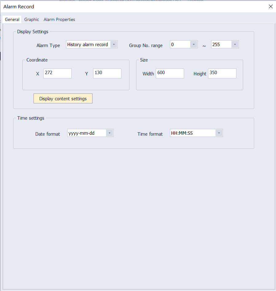
New Alarm record
Introduction: Query all alarm records for a specific group number and display them in a table format in chronological order. The query time period can be dynamically set on HMI, and the display is saved after power-off.
General:
1.Alarm Type : There are three alarm modes including Current alarm record, History alarm record and Alarm event statistics.
(1) Current alarm records: Only the current alarm record will be displayed. If the alarm is triggered, the record will disappear.
(2) Historical alarm records: All alarm and alarm trigger records will be displayed one by one.
(3) Alarm event statistics: Only one record for the same alarm address will be displayed.
2.Group number range: The group number range of the alarm records to be displayed. Alarm records that are not in this range will not be displayed.
3.Time setting: Select the display format of time and date.
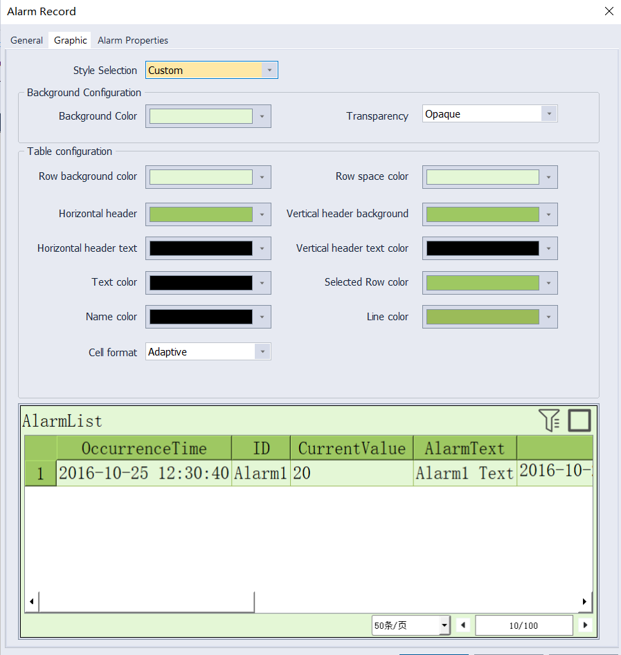
Graphic:
1.Style Selection: Select a system-provided style from the Style Selection menu, or select "Custom" to customize the colors.
2.Cell format: Includes two options: "Adaptive" and "Custom"
①Adaptive: Cells automatically adjust size based on text length.
②Custom: Manually set column widths and row heights for all cells.
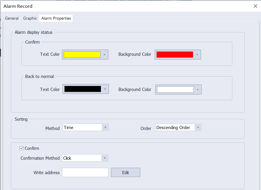
Alaem Properties
1.Alarm Display Status
(1) Confirm: Set the text and background color for confirming an alarm record.
(2)Back to normal: Set the text and background color for the record when the alarm record returns to normal.
2. Sorting
(1)Method: Indicates the field to sort by. The default is time.
(2) Order: Indicates the order to sort by. The default is descending order.
(3) Confirm: Sets the method for confirming an alarm record and the write address.
① Confirmation Method: The method for confirming an alarm record. There are three methods including single-click, double-click, and long press for 3 seconds. The default is single-click.
②Write Address: The write address to be written during confirmation. Confirming will reset the contents of the write address to 0.
Meter

Pointer meter
This object shows the numerical change of the word address by meter format.

Read address: Read the value from the set PLC address.
Data format: It is for data setting. The data format types are as below.
- BCD, 32-bit float
- signed decimal
- unsigned decimal
- 32-bit signed decimal
- 32-bit unsigned decimal
Digits setting: Set directly the maximum and the minimum. Only when the floating point number is selected, can the maximum and minimum value be with a decimal point, and other data formats can't be with a decimal point. If the value is read by the address, then select "variable limits", and fill in the address.
- Min angle and max angle: Data range, if data beyond range will be not inputted.
Variable limits: When checked, low limit address and high limit address could be edit showed below;
Show meter background: This is for setting meter background. When not checked, the background color is transparent; When checked, there are four styles of pointer meter to select according to needs.
Show pointer: When not checked, the pointer is not displayed; When checked, you could set the style and color of pointer.
Show alarm area: It provides alarm function in meter, you could set the 4 areas, and each area corresponds to a different alarm color.
Show scale: Display the scale on the object to observe the value. You need to set major scale, minor scale and scale value.
Meter Type: It sets the angle between the maximum and minimum value. It provides 7 kinds of styles, they are 180°, 210°, 240°, 270°, 300°, 330° and 360°.
Start angle: It sets the position where the minimum value is displayed.
Position&size: Set the position of the object on the screen and the size of the object. The object is displayed as square. If the width or the height of the object is changed, the other data will also be changed.
Result
When configuration is completed, the object is shown below picture when HMI is running.

Bar
The bar graph shows the numerical change of the word address by means of bar graph.
Description

(1) Data setting
- Read address: Read the value from the set PLC address.
- Dual Value Display: Set two read addresses. The bar graph will show the value segment between the two read addresses.
- Data format: It is for setting data format from read address.
- Digits setting: It means the decimal point position. The decimal point position is effective only when data format is floating and decimal.
(2) Display settings
- Type: It is for setting bar display type, it provides two types.
- Type1: Single scale display.
- Type2: Double scales display.
- Bar direction: horizontal display or vertical display.
- Back color: User could freely set the color when check it.
- Text color: Display color of the scale value.
(3) Alarm settings
Alarm setting can be configured to display different colors, with each color corresponding to a different range. There are a maximum of four alert ranges.
(4) Show scale
It provides settings for scale on meter, users could select [Major scale] and [Minor scale], and set color for them.
Result

When configuration is completed, the object shows as above picture, when HMI is running.
Clock
This object displays HMI system time.
Description

- Back type: It is for clock dial style settings; it provides three types.
- Back color: It is for setting color for clock dial, it is invalid when back type is 1.
- Hand type: It is for clock hand style settings; it provides three types.
- Hand color: It is for setting color for hand.
- Show second hand: Check it to display second hand in clock.
- Second hand color: It is for setting color for second hand.
Result
As soon as configuration is completed, the object is shows as below picture, during HMI is running.

Runbar
Run bar object could displays normal text and alarm text. User could select display content according to requirement.
When the alarm text is displayed, it could quickly and timely reflect the status of the current HMI alarm function for easy management and control.
When normal text is displayed, it provides two ways to set the display content to user (static text and dynamic text);
Description

(1) Basic settings
- Type: It is for displaying content settings.
- Move Text: Normal text.
- Alarm: Alarm text.
- Transparence: It sets the transparency of the object background.
- Reverse: it sets text move right to left or left to right.
- Speed: It sets text moving speed.
- Background: It sets object background color.
- Text color: It sets text color.
- Show Border: Check it to show border for object.
- Border: It sets object border color; it is visible only when [Show Border] is checked.
(2) Display content settings
- If it shows static text, please set content in "text".
- If it shows dynamic text, please check [Read Address], and set address and length for it.
- If it shows alarm text, please select alarm information, such as time and date, alarm group number range.
(3) Preview
It is for preview text content in object.
Result
When configuration is completed, the object is shows as below picture, when HMI is running.
- Normal text

- Alarm text

Pie Chart
After inputting data to the specified word address, the proportion of each channel is displayed in the form of a pie chart.

- Reverse:Set the expansion direction of the pie chart.Can choose Clockwise or Counterclockwise.
- Full-circle: Set the pie chart is a Full-circle or not.If not it will only shown the arc from start angle to end angle.Start angle and end angle:Set the start angle and end angle for arc chart.Angle range: 0°-359°.
- Center:Set the center size of pie chart.A pure white circle will be used to occupy the center of the circle.
- Border:Set the color of pie chart's border.
- Border transparency:Set the transparency of pie chart's border.
- Total channels:Set the number of channels,range 2-16.
- Pattern:Set the word pattern of the channels. None, no value shown on pie chart;Data,shown the data value of channels on pie chart;Percentage,shown the percentage of channels on pie chart.
- Font size:Set the font size of the channels value.

- Channel:Select channel to set up.
- Channel color:Set the color of select channel.
- Font color:Set the font color of select channel.

- Start address:Set the start address.The Pie chart will display the values of the consecutive registers starting from the start address.The number of registers is related to the number of channels.
- Data Format:Set the data format of the channel data.6 kinds data format can choose.1.bit BCD;32-bit BCD;16-bit unsigned;32-bit unsigned;32-bit floating;64-bit double.
- Digit:Display format of data on pie chart
Display

Indirect window
Indirect window is used for displaying sub-screen in HMI project. You could control it to display different sub-screens by changing the value of read address.
Description

(1) Screen No.
There are two modes for sub-screen display, one is static screen, and the other is dynamic screen, and switch screen by change read address value. User could only choose one of the two modes.
- Indirect scree No.: It is for setting read address to switch sub-screen.
- Screen No.: Check it to enable static screen mode, and select screen for object.
(2) Control display by address
Control display of the indirect object through bit address.
- Set ON: Display.
- Set OFF: Hide.
(3) Position
It is for setting the position of sub-screen, the value is for coordinates of the top left point of it.
(4) Size
It is for setting the size of sub-screen.
Result
When configuration is completed as below, sub screen will be displayed as picture show.
- Display static sub-screen.
- Use HDX0.0 to control display or hide.

QR Code
It is similar to the universal QR code. You could scan this object to get the connection or content, but it provides content settings for QR code.
Description

(1) QR Set
- Variable QR: It is for setting read address, the content of QR code is from this setting address.
- QR String: It is for set static content for QR code.
Picture
Picture object is for displaying picture in HMI screen. After the picture is imported, the software will automatically convert the color depth of the picture to the picture matching the HMI.
Description

(1) Shape
- Shape: Click shape to open the Shape Library for shape selection.
- Default shape: Every object has its own default shape, click it will back to default.
- Discard: Click it, object will display without shape.
(2) Set Color
This is for set object color basic on shape, not all shape supports change color.
(3) Picture display function
This is advanced function of picture object; user can change display picture when HMI is running. The supported formats are bmp, jpg, png, jpeg. This feature is unavailable for offline and online simulation.
- Root: Set the save location of the picture, which can be set to U disk,SD card,but could not be set to Flash.
- Folder: Set the name of the folder where the picture is located.The folder name can be up to 31 characters. (Note:The picture must be stored in the U disk folder and cannot be stored in the root directory of the U disk.)
- File address: 16 consecutive addresses enter a picture name in the address (need to be the full name of the suffix), if the picture exists, the picture content is displayed; otherwise the default picture is displayed.
Rotation picture
Rotation picture can rotate the image at a specified center or rotate it in a certain way. It is determined by the property settings.

Position: Display the position of the rotation picture in the screen.
Counter-Clockwise: It sets the rotation direction of the picture. The default is to rotate clockwise. When checked, the rotation direction is counterclockwise.
Appearance: It sets picture for object, the picture is selected from Shape.
Data format
- Data format: It sets data format for [Address]->[Rotation angle].
- BCD
- 32-bit float
- 16-bit signed decimal
- 16-bit unsigned decimal
- 32-bit signed decimal
- 32-bit unsigned decimal
- Min. angle: It sets the starting angle of rotation (Valid in auto-rotation mode).
- Max. angle: It sets the ending angle of rotation (Valid in auto-rotation mode).
Rotation angle: The rotating angle is determined by designated address;
Rotation center: It shows the rotation center coordinates;
Auto-rotation: Taker the center of the image as the center of the picture when it is rotating.
Cycle time: Object will rotate every cycle time. Unit:100 ms.
Rotation angle: Object rotates designated angle everytime.
Return: Object will be reset to original position after maximum angle reached.
Enable auto-spin: When the address is set to ON, the picture will rotate automatically.
Hide: Control the hiding status of the object through the status of the control bit address. The hiding mode can be divided into hide when OFF and hide when ON.
Drop-down List
Drop-Down list is designed for display the designated state by text, to select the text in the list, the corresponding state will change, and the write address will change to the designated state value.
The drop-down list could write word address, and the value range is 0 to 31. The corresponding value can be displayed by text in the object. Click the drop-down box on the right of the object to list all the status text, and the drop-down box will be automatically withdrawn after setting.
(1) General

1) Edit
- Read Address: The data from designated address will be displayed.
- Same read-write address: Configure "Write Address" as the same as "Read Address".
- Write Address: Write data to designated address. The address can be different from "Read Address".
2) Format
Set data format for object, it provides 16-bit unsigned decimal,16-bit BCD, 16-bit unsigned decimal, 32-bit BCD, 32-bit unsigned decimal, and 32-bit unsigned decimal.
3) State count
It could set the total number to display in the drop-list and supports up to 128 states (1 to 128). The default value of state is corresponding to the number of states. (State 1 corresponding to value 1). You can also click "state values" to set it according to your needs.
State value: User can set different values to correspond to different states, the setting window as below figure shows.
For example
By default, when value of read address is 0, object displays state 0.
If change settings as below figure shows.
When value of read address is 11, object displays state 1.
4) Advance
It provides two types for this object.
- Normal Type: It makes object as normal drop-down list object.
- User name: it is for user login permissions. User name and group name in user permissions are mainly displayed.
(2) Text settings
Every state requires text, the settings as below description, the normal settings please refer to common setting. This section will show special settings for it.


1) Centre
Check it to make the text centered;
2) Enable states text control
You can dynamically modify the text content in different states. When this feature is enabled, the text for each state set in the normal mode is invalid.
- Current state: It is for setting state number for modification. For example, if the value is 3, it means that the text information in state 3 will be modified.
- Text address: This address is used for the operation of the text component and is used to input the content displayed in the state. The length of the text is the number of text characters that can be entered, ranging from 1-127 characters.
- Trigger set text: This address is used for saving modification.
3) Read state text from address
- Text start address: The first address of occupied multiple consecutive addresses. Address length: [Text length/2] *[state number +1].
- For example: 10 states, the address length= (10/2) *(10+1) =55. It set HDW100 as start address, so the HDW100-HDW104 stores the currently selected text content, the HDW105-HDW109 displays the text in the first state, the HDW110-HDW114 displays the second, and so on.
- Refresh: The drop-down list status value is updated according to the text address content. The drop-down list is not updated immediately, when the data in the text address change is completed, only the refresh is triggered, it will update.
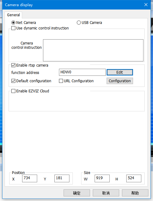
Camera display
Video display is advanced function in PI HMI, this object displays the camera screen in HMI, there are two modes, one is IP camera, and the other is USB camera. But IP camera requires settings in [Project settings], the detailed information, please refer to [Camera].
IP Camera
(1) General

(1) Mode select
It is used for selecting modes; each mode uses different settings.
(2) Use dynamic control instruction
Read a string from designated system address, and then combine the instruction to control the camera image.
When the dynamic control command is disabled, the complete camera control command need to be entered in order to display the camera contents.
(3) Camera control instruction
This is for entering static instruction for camera, so that users can operation camera when HMI running;
(4) Enable rtsp camera
This is another way to control camera, check it and set the function address.
Camera Display usage method
(1)Usage 1: Suitable for users know camera account, password and device serial number.
Add the camera display object, select Net Camera, and enable rtsp camera and configured with a functional address, the followings use HDW0 as as example:
Register | Function | Length | |
|---|---|---|---|
HDW0 | User name | 20 words | |
HDW20 | Password | 20 words | |
HDW40 | Alias | 20 words | |
HDW60 | Device Serial Number | 43 words | |
HDW103 | Camera ID | 1 word | |
HDW104 | Camera control | 1 word | |
HDX104.0 | Open Camera | ||
| HDX104.1 | Close Camera | ||
| HDX104.2 | Camera up | ||
| HDX104.3 | Camera down | ||
| HDX104.4 | Camera left | ||
| HDX104.5 | Camera right | ||
| HDX104.6 | Screenshots | ||
| HDX104.7 | Binding camera | ||
| HDX104.8 | Set alias | ||
| HDX104.9 | Camera stops moving | ||
HDW105 | Camera Status =0:Camera disconnected; =1:Camera connected properly; =2:Camera is being connected. | 1 word | |
HDW106 | Screenshot save location: =0:Screenshot save in Flash/IPCameraScreenShot; =1:Screenshot save in U Disk/IPCameraScreenShot; =2:Screenshot save in SDCard/IPCameraScreenShot. | 1 word | |
Fill in the camera ID with the camera serial number queried by "Camera Search Module", trigger the binding address, and fill in the camera information (user name, password, device serial number, etc.) of the ID into the corresponding function address.
If the "Camera Search Module" is not enabled, you need to enter the camera information manually: user name, password, device serial number (S/N), which can be obtained from the label on the camera body.
Trigger the "Open Camera" address to view the surveillance screen of the camera.
If the camera is successfully opened, you can set the alias of the camera, control the up/down/left/right movement of the camera (provided that the camera supports up/down/left/right control), and take screenshots.
If the camera is off, you can't set alias, camera rotation, screenshot, etc.
(2) Usage 2: Suitable for users know the camera account, password and camera IP
After enabling the rtsp camera and configuring the function address, additionally check Default configuration option, the configuration method and the function can address as follows.


Register | Function | Length | |
|---|---|---|---|
HDW0 | User name | 20 words | |
HDW20 | Password | 20 words | |
HDW40 | IP | 8 words | |
HDW48 | Port | 1 word | |
HDW49 | HDX49.0 | Open Camera | 1 word |
HDX49.1 | Close Camera | ||
HDX49.2 |
| ||
HDX49.3 |
| ||
HDX49.4 |
| ||
HDX49.5 |
| ||
HDX49.6 | Screenshots | ||
HDX49.7 | |||
HDX49.8 |
| ||
HDX49.9 |
| ||
HDW50 | Camera Status =0:Camera disconnected; =1:Camera connected properly; =2:Camera is being connected. | 1 word | |
HDW51 | Screenshot save location: =0:Screenshot save in Flash/IPCameraScreenShot; =1:Screenshot save in U Disk/IPCameraScreenShot; =2:Screenshot save in SDCard/IPCameraScreenShot. | 1 word | |
If you have set the default settings, directly trigger the function address to trigger the opening of the camera.
The camera configured via ip only supports, turn on, turn off, screenshot basic functions.
(3)Usage 3: Suitable for users know the address of rtsp stream play.
After enabling the rtsp camera and configuring the function address, additional check URL configuration option, configuration method and function can address as follows.

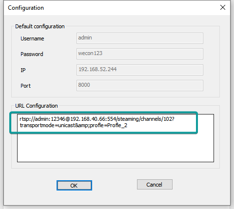
Register | Function | Length | |
|---|---|---|---|
HDW100 | RTSP URL | 127 words | |
HDW228 | HDX228.0 | Open Camera | 1 word |
HDX228.1 | Close Camera | ||
HDX228.2 | Reserved | ||
HDX228.3 | Reserved | ||
HDX228.4 | Reserved | ||
HDX228.5 | Reserved | ||
HDX228.6 | Screenshots | ||
HDX228.7 | Reserved | ||
HDX228.8 | Reserved | ||
HDX228.9 | Reserved | ||
HDW229 | Camera Status =0:Camera disconnected; =1:Camera connected; =2:Camera is being connected. | 1 word | |
HDW230 | Screenshot save location: =0:Screenshot save in Flash/IPCameraScreenShot; =1:Screenshot save in UDisk/IPCameraScreenShot; =2:Screenshot save in SDCard/IPCameraScreenShot. | 1 word | |
If you have set the default settings, directly trigger the function address to trigger the opening of the camera.
The camera configured via ip only supports, turn on, turn off, screenshot basic functions.
EZVIZ Cloud Description


EZVIZ Camera Parameters Comparison for HMI Series
| HMI Series | System Version | Number of Cameras Supported | Actual Screen Support Display Camera or not | V-NET Display | V-NET APP Display |
|---|---|---|---|---|---|
| 8000 Series | HMI V2.0 | 1 | Yes | Yes | Yes |
| 9000 Series | HMI V2.0 | 4 | Yes | Yes | Yes |
| 3000ig Series | HMI V2.0 | 1 | No | Yes | Yes |
| 8000ig Series | HMI V2.0 | 4 | Yes | Yes | Yes |
The function address will occupy the 125 word address, the following table is using the HDW6000 as a example:
| Register | Description | Length | Data Format |
|---|---|---|---|
| HDW6000 | AppKey of EZVIZ Cloud | 20 Words | String |
| HDW6020 | AppSecret of EZVIZ Cloud | 20 Words | String |
| HDW6040 | Device S/N of EZVIZ Cloud | 43 Words | String |
| HDW6083 | Channel number of EZVIZ Cloud | 1 Word | 16bit Unsigned |
| HDW6084 | Device IP of EZVIZ Cloud | 16 Words | String |
| HDW6100 | RTSP Port of EZVIZ Cloud | 1 Word | 16bit Unsigned |
| HDW6101 | Verification code of EZVIZ Cloud | 20 Words | String |
| HDX6121.1 | Confirmation of binding EZVIZ camera (=1, Confirm; =Others value, Unconfirm) | 1 Bit | Bit |
| HDW6122 | Device function control | 1 Word | 16bit Unsigned |
| HDW6123 | Device status (=0, Close; =1, Open) | 1 Word | 16bit Unsigned |
| HDW6124 | Result code of function control(HDW6122) | 2 Words | 32bit Signed |
When the function control HDW6122 set to different value, it will trigger different function. After triggered, the HDW6122 will be reset to 0. The specific introduction like follows:
| Register Value | Function Description |
|---|---|
| 1 | Open camera |
| 2 | Close camera |
| 3 | Move up |
| 4 | Move down |
| 5 | Move left |
| 6 | Move right |
| 7 | Move upper left |
| 8 | Move lower left |
| 9 | Move upper right |
| 10 | Move lower right |
| 11 | Zoom in |
| 12 | Zoom out |
| 13 | Short focal length |
| 14 | Long focal length |
| 15 | HD clarity |
| 16 | Smooth clarity |
| 17 | Stop control |
The result code of function control will be displayed in HDW6124, the specific code as following table shows:
| Result Code | Description | Remark |
|---|---|---|
| -1 | Operation failed | Other reason(For example network error, device configuration error, etc.) |
| -1001 | Internal error | Suggest to retry |
| -1002 | Camera search: Request parameter is empty | Confirm the account and password whether correct or not |
| -1003 | Camera search: Search failed | Confirm the device ethernet whether connect normal |
| -1004 | Camera binding failed: Invalid camera ID | Confirm the camera ID whether is in the valid range |
| -1005 | Camera opening failed: Cannot match the corresponding camera | Confirm the account, password and S/N whether correct or not |
| -1006 | Camera opening failed: Cannot adapt minimum resolution | Confirm the camera supports ONVIF protocol or not |
| -1007 | Camera opening failed: Cannot get the rtsp stream address | Confirm the camera supports ONVIF protocol or not |
| -1008 | Camera opening failed: Cannot adapt the camera parameters | Confirm the camera supports ONVIF protocol or not |
| -1009 | Camera opening failed: Open video stream failed | Confirm the camera whether is on running status, or whether open the camera too frequently |
| -1010 | Camera closing failed: Camera on the closed status | Confirm the camera whether is on running status or not |
| -1011 | Camera closing failed: Camera on the closed status | Confirm the camera whether is on running status or not |
| -1012 | Screenshot failed: Camera not opened | Confirm the camera whether is on running status or not |
| -1013 | Screenshot failed: Execution error occurred | Confirm the camera whether is on normal running status or not |
| -1014 | Alias setting failed: Cannot match the corresponding camera | Confirm the S/N whether correct or camera whether is on running status |
| -1015 | Pan-tilt controlling failed: Camera on the closed status | Confirm the camera whether is on normal running status or not |
| -1016 | Pan-tilt controlling failed: Camera match failed | Confirm the account, password and S/N whether correct and the camera device whether supports pan-tilt movement |
| 1 | Operation success | Operation success |
| 201 | Play address created | Do not open the camera frequently |
| 401 | Unauthorized | Please contact the device administrator to enable operation permission |
| 403 | Operation prohibited | Please contact the device administrator to enable operation permission |
| 404 | Play address not obtain | Confirm the device network status |
| 403 | User does not exist | Confirm the AppKey and AppSecret whether correct |
| 10001 | Parameter error | Confirm the basic information of EZVIZ Cloud whether correct |
| 10002 | AccessToken abnormal or expire | Please try to reopen the camera |
| 10005 | AppKey abnormal | AppKey is frozen, please contact with EZVIZ customer service to unfreeze |
| 10017 | AppKey does not exist | Confirm the AppKey whether correct or not |
| 10030 | AppKey is unmatched with AppSecret | Confirm the AppKey and AppSecret whether correct |
| 20001 | Channel does not exist | Confirm the camera whether re-added or channel parameter whether changed |
| 20002 | Device does not exist | Confirm the S/N whether correct |
| 20006 | Network abnormal | Confirm the device network status, try again later |
| 20007 | Device offline | Confirm the devie whether online or not |
| 20008 | Device response timeout | Operation too frequent, try again later |
| 20014 | S/N illegal | Confirm the S/N whether correct |
| 20018 | The current user does not own the device | Confirm the S/N whether correct |
| 20032 | Channel does not exist under the current user | Confirm the camera whether re-added or channel parameter whether changed |
| 49999 | Data abnormal | Please try to reopen the camera |
| 60000 | Device does not support pan-tilt controlling | Confirm the device whether supports pan-tilt controlling or not |
| 60001 | The current user does not have the permission of pan-tilt controlling | Please contact the device administrator to enable operation permission |
| 60002 | Device tilt reaches to the upper movement limit | Device control reach to limitation, do not repeat the operation |
| 60003 | Device tilt reaches to the lower movement limit | Device control reach to limitation, do not repeat the operation |
| 60004 | Device pan reaches to the left movement limit | Device control reach to limitation, do not repeat the operation |
| 60005 | Device pan reaches to the right movement limit | Device control reach to limitation, do not repeat the operation |
| 60006 | Current pan-tilt controlling operation failed | Pan-tilt operation failed, try again later |
| 60019 | Device stream is encrypted | Using the EZVIZ Cloud client software to close the stream encrypted, then remote monitoring will be able to use |
| 60020 | Unsupport this command | Confirm the device whether supports this operation or not |
Default Configuration: Enable the default configuration, the initialization of the EZVIZ cloud camera display components will use the default configuration for binding, the screen can also be modified through the function address configuration information; do not enable the default configuration, the default initial configuration of the EZVIZ cloud camera display components are empty.
In the default configuration, the following are required:
AppKey: EZVIZ cloud application information AppKey, up to 32 characters in length, only letters and numbers can be entered, which can be obtained through the EZVIZ cloud open platform.
Secret: EZVIZ cloud application information Secret, up to 32 characters in length, only letters and numbers can be entered, available through the EZVIZ cloud open platform.
Channel number: EZVIZ cloud device source channel number, 1~65535, no special modification, generally defaulted to 1, which can be obtained by viewing the EZVIZ cloud client software.
S/N: EZVIZ cloud device serial number, 0 to 80 characters in length, only letters, numbers and "-" can be entered, which can be obtained through the device information.
In the default configuration, the following are optional:
IP: EZVIZ cloud device IP, which can be obtained by viewing the EZVIZ cloud client software.
RTSP Port: EZVIZ cloud device source rtsp port number, range 0~65535, no special modification, generally default to 554, can be obtained by viewing the EZVIZ cloud client software.
Verification Code: EZVIZ cloud device authentication code, up to 32 characters in length, obtainable through device information.
USB Camera
(1) General

1) Mode select
It is used for selecting modes; each mode uses different settings;
2) Camera settings
Function address: It occupies a word for functional operation. Different value means different operations, as below table shows:
| Value | Operation |
|---|---|
| 1 | Enable the screenshot function |
| 2 | refresh camera display object |
Camera state: It shows the current camera states. It occupies a word address. Different value means different operations, as below table shows:
| Value | Operation |
|---|---|
| 1 | Load the camera function successfully |
| 2 | Failed to load the camera function |
| 3 | Camera does not exist |
| 4 | Camera is not running |
| 5 | Initialize the camera successfully |
| 6 | Failed to initialize the camera |
| 7 | Screenshot successfully |
| 8 | Failed to screenshot |
| 9 | Connected camera |
| 10 | Removed camera |
| 11 | The cache is full |
| 12 | The cache is abnormal |
3) Screenshot storage
The current screenshots are only allowed on the SD card. When the SD card does not exist the system will cache the latest 10 screenshots.
Picture name: The name of the image is controlled by the address. The length of the file name is limited to 64 words. If the image name address is not set, it will be named according to the time and displayed as [YYYYMMDDHHMMSS.bmp] and screenshot format is [.bmp].
4) Global screenshot
If this function is enabled, camera display object can perform the screenshot operation when HMI is running and save it as a . BMP image.
If this function is disabled, camera display object only performs the screenshot operation when it is displayed on screen.
5) Resolution
The resolutions of different types of USB cameras are different, and the user can select the corresponding resolution according to the camera. When the user is unsure of the resolution of the camera, start with the smallest resolution until the image is clear.
6) Use resolution size
Coordinate displays the object location on the screen, and size is the length and width of the object.
Camera control
This is for control camera; This object need to be used with camera display object.
Description

1) Use dynamic control instruction
Read a string from designated system address, and then combine the instruction to control the camera image.
When the dynamic control command is disabled, the complete camera control command is entered in order to display the camera contents.
2) Camera control instruction
This is for entering static instruction for camera so that users can operate camera when HMI running.
3) Control bit
Trigger the switch to control the instruction.
4) Enable beep
The object will beep when operate.
Flow component
The flow components are mainly used to reflect the flow state in process flow production. User could set the style of flow components according to requirements.
Description

(1) Color
- FlowFrn: It sets outer border color of flow component.
- Block: It sets the block color of flow component.
- FlowBg: It sets background color of flow component.
(2) Detail
- Pipe width: It sets background width of flow component.
- Block width: It sets block width of flow component.
- PipeFrn width: It sets outer border width of flow component.
- Block length: It sets block length of flow component.
- Transparence: It sets transparence of flow component. (from opaque (0) to full transparence (100)). You could cooperate with transparence and other settings to meet display requirements.
- Ratio: It sets the display ratio of block and background (Display density of the block in flow component).
- Speed: It sets flow speed of the block during HMI running.
(3) Control
It flows automatically by default, and the direction is from left to right, up to down.
- Reverse: It sets flow in reverse (default is left to right).
- Variable: It sets bit address to control reverse flow or not.
- Set OFF: Forward
- Set ON: Reverse
- Address: It sets bit address to control flow or not.
- Set OFF: Stop
- Set ON: Flowing
(4) Preview
It is for preview object.
Printer
The printing object is primarily suitable for printing out or screenshots saving when connected to micro printer.
Printer has two types: serial printer and USB printer. Printf (printext function) should be called when it's used to print fixed message in a script.
Printer protocol
HMI provides printer protocol to users as below. If users want to connect printer to HMI, protocol is necessary.


Description

(1) Display settings
- Direction: Four direction choices in printing: 0, 90, 180, and 270.
- Zoom in: Check "Zoom in" to zoom printing content in proportion to paper size.
(2) Trigger mode
- Trigger address: When trigger address turns ON. The printer starts to respond operationally.
- Printer\ Save: It sets operation for this object, printer object could support sending printing command to printer device, and including screenshot.
(3) Save path
Valid when the save mode is selected, screenshot the content in printing object area, and save it in specified storage and folder, when trigger address turns ON.
Folder: It's available to select an SD card or USB disk. Set the file name to "Abc" in folder, and it would automatically generate a folder "Abc" when you save picture the first time, and all the pictures will save in this folder. The folder name consists of mixed uppercase and lowercase letters and numbers within 32 characters.
Related issues
- The printer supports the following models:
- Serial port printer: WH-E22、WH-A6, WH-A7, WH-A9, WH-E21, WH-AA, E222R90-0DE1182TGA, SP-RMD6A, SP-RMD6B, SP-RMD8A, SP-RMD8B, SP-RMD8C, SP-DVII, SP-RME4.
- USB printer: SP-EU80, SP-EU80N, SP-EU801SU-USB, SP-RME3UHB, SP-RME4, SP-RMD8CUH-USB.
- How to use USB printer and USB disk at the same time?
- Plug the USB interface in the HMI into the Hub to expand the USB interface.
PDF Reader
The PDF reader can open the. pdf suffix file in the U disk or SD card for browsing and reading.
1.Object setting

File path
- Root: You can choose to open PDF files in USB drive or SD card. each PDF reader can only choose to open files in one of the storage devices of USB drive or SD card.
- Folder:You can manually enter or insert the USB drive to select the directory where the PDF file is located. Only PDF files or folders under the folder can be opened after selected. When the folder path is empty, the root directory under the USB drive/SD card is opened by default.
- File name:Set the address of the Filename.Select the word address, the maximum length is 256 characters, occupying 128 addresses.
Control address
- Control:Set the address of object control.Select the word address,occupying up to 3 addresses.
- Page control:If page control is checked,then the two addresses starting from the control address will become the page control address. For example: control address as HDW0, then Current page number as HDW0,the Total Pages as HDW1.
- Zoom ratio control:If page control is checked,then the third address will become the Zoom ratio control address.For example:control
Background configuration
- Background color: change the color of PDF reader's background.
2.PDF Reader Operation

- Open the file browser
- Single page display
- Multi-page display
- Previous page (single page mode)/Previous four pages (multi-page mode)
- Next page (single page mode)/next four pages (multi page mode)
- Swipe to zoom out PDF display content
- High support full display.
- Wide support full display.
- Rotate 90 degrees to the left.
- Rotate 90 degrees to the right.
Media Player
Configuration
Play videos from U Disk drive or SD card.
Model restriction: 8000ig, RH and 9000ig
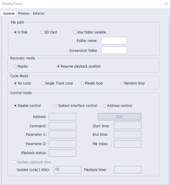
File path:
There are two optional file path, U Disk and SD card.
Folder name: The name of a file storing videos.
Screenshot folder: The name of a file storing screenshot of video.
Use folder variable: Use specified address to type the name of folder and screenshot.
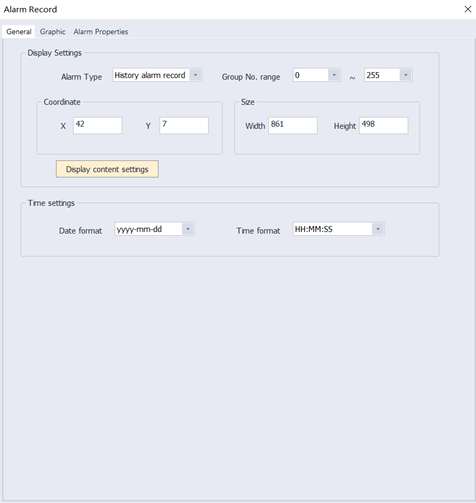
Recovery mode:
Replay: Start the video from the beginning.
Resume playback position: After power-off or exit, resume playback from the last interruption position when restarting.
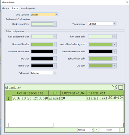
Cycle Mode: Content playback methods for different scenarios
(1) No loop: The video playback is executed only once and stops automatically after it ends.
(2) Single Track Loop: A single video plays repeatedly, never stopping.
(3) Playlist loop: Videos are played in a fixed order in the file
(4) Random loop: Videos are played in a random order in the file
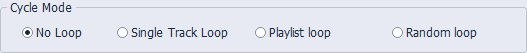
Control mode:
Disable control: There is no operation button, and the playback status cannot be manually controlled. The system automatically plays the list file until the end.
System interface control: Provides user interface buttons, mutually exclusive with address control.
Address control: Use specified address to Implement video control function.
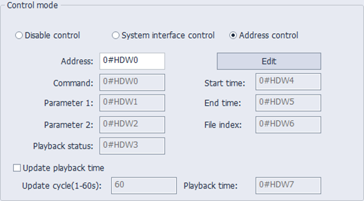
Preview:
Load video: Load a video and preview the video playback effect before downloading HMI project.
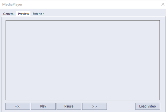
Function button
 : Play
 : Pause
 : Stop
 : Replay
 : Previous
 : Next
 : Fast rewind
 : Fast forward
 : Screenshot
 : Full screen
 : Exit full screen
Cycle mode:
 : No loop
 : Single Track loop
 : Playlist loop
 : Random loop
Window:
 : Minimalist mode switch
 : Minimalist mode switch
Playback address control function
| Operation | Command | Parameter 1 | Description |
| Play/Pause | 1 | N/A | Address mode control. Play status address will be 16 during playing. Play status address will be 256 during Pause. |
| Replay | 2 | N/A | |
| Stop and close file | 3 | N/A | Play status address will be 4096 during Stop. |
| Play previous video | 4 | N/A | 1.If File index is originally 0, the video will be played again. 2.If file cannot be found, Play status address will be 8. |
| Play next video | 5 | N/A | 1.If the next file cannot be found, the first video in the list (file index 0) will be played. 2.If the file cannot be found, the Plays tatus address will be 8. |
| Fast rewind | 6 | Specified number of seconds | 1.Rewind the video by the specified number of seconds from the current time and start playing again. 2.If the video is currently paused, this operation will cause it to remain paused. 3.If the specified time is less than the start time, the video will restart playing. |
| Fast forward | 7 | Specified number of seconds | 1.Fast-forward the specified number of seconds from the current time and start playback. 2.If the video is currently paused, this operation will cause it to remain paused. 3.If the specified time exceeds the end time, the video will end immediately. |
| Volume | 8 | Specified volume (0-50) | Default volume is 50. |
| Start time | 9 | Specified position (Unit: s) | The specified position should be less than the end time. If it exceeds the end time, the system will end the video directly. |
| Play index file | 10 | File index | The files will be sorted by name. The file index is 0, pointing to the first file, and so on. If the file cannot be found, Play status address will be 8. |
| Update playback time | N/A | Video will be played and the current playback progress (in seconds) will be updated in real time according to the set update cycle. |
Draw
It provides function of drawing graphics, setting text, displaying pictures, this part contains Text, Line, Polygon, Cycle, Arc, Rectangle, Broken Line, Linear Scale, Arc scale, Table.

Date
Date object displays local system date on the HMI screen.

(1) Display
- Open: It locals to [Shape] to select object background picture.
- Default: Click it to reset object background.
- No Shape: It sets transparent background for this object.
- Font: It locals to [Font library] to select font for text in object.
(2) Text color
It sets color for text in object.
(3) Color
Valid when select SVG picture from [Shape], user can modify SVG color according to requirements.
(4) Data format
It sets object display date or week, and format, detailed please refer to below table.
| Classification | Properties | Display style |
| Format | Show date | YYYY/MM/DD: year/month/day MM/DD/YYYY: month/day/year DD/MM/YYYY: day/month/year |
| Show week | Chinese 1 English 1 Chinese 2 English 2 |
Time
Date object displays local system time on the HMI screen

(1) Display
- Open: It locals to [Shape] to select object background picture.
- Default: Click it to reset object background.
- No Shape: It sets transparent background for this object.
- Font: It locals to [Font library] to select font for text in object.
(2) Text color
It sets color for text in object;
(3) Color
Valid when select SVG picture from [Shape], user can modify SVG color according to requirements;
Text
It adds text to HMI screen, and an object can be displayed in 8 languages (set in "All Languages") with a special address setting.

(1) Current state
It is used to switch the object states, but [Text] object only has one state, so this function is invalid.
(2) All language
Because in PI HMI, all object can support text in 8 languages, so click it to open the 8 language edit window as below shows. And each language can set different font.

(3) From Text Library
If user already setting text in "Text library", you could use text from "Text library" directly.
(4) Windows
It displays three languages content and provides text display setting access.
(5) Text color
It sets color of text in object.
(6) Text background
It sets object background and it only supports color.
Table
It is displayed in a table format on the HMI screen to meet the display needs of user.

(1) General
- Rows: It sets rows for table.
- Columns: It sets columns for table.
- Table line width: It sets table line width, the larger the value, the thicker the line.
- Frame line width: It sets table frame line width, the larger the value, the thicker the line.
- Border: It sets table line color, including table line and frame line.
- Transparence: It sets the transparency of the object background.
- Fill style: There are two options for it, one is display background, and the other is no background.
- Background: Valid when selecting display background in "Fill style".
(2) View
It is for preview object.
Line
It is displayed in line format in the HMI screen to meet the display needs of user.

(1) Display settings
- Line: It sets line color.
- Line type: It sets line type; it provides 9 types for user.
- Transparence: It sets the transparency of the object background.
(2) Line width control
In basic display settings, the line width can't be changed, but you could change width by address.
Read the numerical value of address to control the width of line. Display range of numerical value:1-10.
(3) Coordinate control
Dynamically set the position coordinate between two points in line. Set four addresses respectively corresponding to the starting point and end point coordinate. If the numerical value of coordinate is over interface, the object will not be displayed.
(4) Color control
Dynamically set the color of the line. The values of the color RGB are controlled by three addresses, and the value range from 0 to 255.
(5) View
It is for preview object.
Polygon
It is displayed in polygon format on the HMI screen to meet the display needs of user.
Right click to close polygon and then complete the creation procedure. Select the polygon, then click its point position to change its vertex coordinate after it is created.

(1) Display settings
- Border color: It sets border line color.
- Border type: It sets border line type.
- Border width: It sets border line width.
- Transparence: It sets the transparency of the object's background.
- Coordinate editing: It changes coordinate for all points in this object, as below shows.

- Filling pattern: It can't be modified now.
- Background: It sets background color of object.
(2) Transparence control
Read the numerical value of address, control the transparency; value range: 0 to 100.
(3) Color control
Dynamically set the color of background. The values of the color RGB are controlled by three addresses, and the value range from 0 to 255.
(4) View
It is for preview object.
Cycle/ Ellipse
It is displayed as cycle on HMI screen to meet the display needs of user.

1) Display settings
- Border: It sets border line color.
- Frame width: It sets border line type.
- Frame type: It sets border line width
- Pattern: It sets background type, there are four types.
- Background: It sets background color of object, invalid when selecting [No fill] in [Pattern]
- Transparence: It sets the transparency of the object's background.
2) Transparence control
Read the numerical value of address, control the transparency; value range: 0 to 100.
3) Cycle
Check if it is for circle; uncheck it for ellipse.
4) Color control
Dynamically set the color of background. The values of the color RGB are controlled by three addresses, and the value range from 0 to 255.
5) Move Control
Dynamically set the position coordinate and size of circle/ellipse when HMI is running.
- X axis: The length value moved along the X axis comes from the set address.
- Y axis: The length value moved along the Y axis comes from the set address.
- Radius address: The radius length of the circle/ellipse from the set address.
Arc
The software uses arc drawing to specify the starting point and ending point, using a counterclockwise drawing method. The contour, start and end points of the arc can be modified on the screen. If the user wants to change the start and end points of the arc on the screen, the arc should be selected firstly.
Description
(1) View
It is for preview object.
2) Display settings

- Border: It sets border line color.
- Line type: It sets border line width.
- Line width: It sets border line type.
- Fill style: It sets background type, there are four types.
- Transparence: It sets the transparency of the object background.
- Background: It sets background color of object, invalid when selecting [No fill] in [Pattern].
(3) Only show arc
Check it for displaying arc; Uncheck it for displaying sector;
(4) Transparence control
Read the numerical value of address, control the transparency; value range:0-100.
(5) Color control
Dynamically set the color of background. The values of the color RGB are controlled by three addresses, and the value range from 0 to 255.
(6) Angle control
Dynamically set the shape of the arc, start angle and end angle are controlled separately by setting address.
(7) Angle
It displays and sets the starting and ending angles of the arc.
Broken line
The line segments are linked end-to-end to form a broken line, whose vertex coordinate can be modified by drafting, just like polygon.

(1) Display settings
- Line color: It sets line color.
- Line type: It sets line type.
- Line width: It sets line width.
- Transparence: It sets the transparency of the object line.
- Coordinate editing: It changes coordinate for all points in this object, as below shows.
(2) Transparence control
Read the numerical value of address, control the transparency; value range:0-100.
(3) Line width control
In basic display settings, the line width can't be changed, but user can change width by address.
Read the numerical value of address to control the width of line. Display range of numerical value:1-10.
(4) View
It is for preview object;
Linear scale
The linear scale is a linear scale that draws the specified area with a bisector. The specific scale of the scale can be marked with static text.

(1) Display settings
- Line color: It sets all line in object (including main and sub scale).
- Display direction: It provides four modes for display.
- Main scale: It sets the cell of the main scale.
- Sub scale: It sets the cell of sub scale for every main scale.
(2) View
It is for preview object.
Arc scale
It displays the scale within the specified arc area. The arc scale needs to specify a center coordinate. The inner and outer circles have two concentric circles that specify the scale length and the display area. The scale is distributed counterclockwise between the start angle and the end angle.
Description

Line color: It sets all line in object (including main and sub scale).
Display direction: It provides four modes for display.
Main scale: It sets the cell of the main scale.
External radius: It sets the distance from the center of the circle to the outer circle of object.
Inner radius: It sets the distance from the center of the circle to the inner circle of object.
Start angle: It displays and sets the start angles of the arc.
End angle: It displays and sets the end angles of the arc.
Custom object

Customized object
Customized object is provided for users to design the universal interface of object freely to meet customization requirements.

- Function Address: The numerical value in this address is used as the function code of object to handle the corresponding operation.
- DLL file name: Select needed dll file. (i.e. dll files provided by users)
- Custom address: Users can add some function address to cooperate with dll file to complete other operations.