This chapter provides information about basic functions and configuration in PIStudio.
Alarm
Bit alarm
Click "Project"→"Bit Alarm", it is displayed as the following figure.

Group No.: Group number of Bit alarm. The name is unique and cannot be duplicated.
Bit Address: Bit address of alarm monitoring
- Record bit alarm by default: Whether to record the alarm history data of bit alarm, if checked, it will be saved in the designated storage location.
- Not save alarm OFF: If checked, after the alarm is dismissed, the corresponding alarm records will be deleted from the log file.
Upload to Cloud: The data upload by "bit alarm" is stored in the Cloud and it is alarm data. (Only ig series and 8000/9000 series with -R after system upgrade are supported)
Alarm Condition: It sets alarm trigger condition, there are two types: alarm when ON and alarm when OFF.
Alert: It is used to mark whether the alarm has occurred. if an alarm occurs, the address of "control bit" will be written to 1. If "clear alert when alarm OFF" is checked, the address of "control bit" will be written to 0.
Beep when alarm ON: The beep works when the alarm is triggered. If "beep once" is checked, bit address alarm only beep once and stop.
Content: It is used for setting alarm content (command).
Alarm Screen: Pop-up alarm screen (it need to be sub-screen);
- Position: The location of the screen alarm display.
- Pop-up Interval: The time of reopen the alarm screen when alarm screen closed.
- Pop-up once: Pop up alarm screen once, and the screen would not pop up again
- Close window when alarm off: Automatically close the alarm screen when alarm off.
Operating Procedures of Adding One Alarm
- Click "Project"→"Bit Alarm" as below shows.

- Click "Add" button to open "Bit Alarm" setting window.

- Set "Bit Address".
- Set "Alarm Condition".
- Set "Content".
- Other settings can be set according to the actual situation".
- Click "OK" button to complete settings.
Word alarm
Word alarm is to monitor the word address of a device. If the data meets the set conditions, an alarm will be generated.
Click "Project"→"Word alarm", it is displayed as the following figure.

Alarm Name: You can set alarm name for it. Alarm Name can only consist of (0~9), (a~z), (A~Z), ('_'), (' ') and other non-English characters.
Alarm Address: It is used for setting word address for word alarm, such as HDW0.
Data Format: 16-bit unsigned decimal, 16-bit signed decimal, 16-bit BCD, 32-bit unsigned decimal, 32-bit signed decimal, 32-bit BCD, 32-bit float.
Group No.: Group number of word alarm. The name is unique and cannot be duplicated.
Upload to Cloud: The data upload by "word alarm" is stored in the Cloud and it is alarm data. (Only ig series and 8000/9000 series with -R after system upgrade are supported)
Record alarm: Whether to record the alarm history data of word alarm, if checked, it will be saved in the designated storage location.
Not save alarm OFF: If checked, after the alarm is dismissed, the corresponding alarm records will be deleted from the log file.
Alarm Condition: Alarm is triggered when designated address meets the alarm condition, it provides four conditions;
- High alarm: Alarm is triggered when it reaches high limit. It can be a constant or a variable
- Low alarm: Alarm is triggered when it reaches low limit. It can be a constant or a variable
- Range alarm: Alarm is triggered when it exceeds the range. It can be a constant or a variable
- Equivalent alarm: Alarm is triggered when the value equals to the given data. It can be a constant or a variable
Alarm Info: It is used for setting alarm content (command);
Alert: It is used to mark whether the alarm has occurred. if an alarm occurs, the address of "control bit" will be written to 1. If "clear alert when alarm OFF" is checked, the address of "control bit" will be written to 0.
Alarm Screen: Pop-up alarm screen (it need to be sub-screen);
- Position: The location of the screen alarm display.
- Pop-up Interval: The time of reopen the alarm screen when alarm screen closed.
- Pop-up once: Pop up alarm screen once.
- Close window when alarm off: Automatically close the alarm screen when alarm off.
Beep when alarm ON: beep works when the alarm is triggered, in the default mode, the beep works until the alarm is released.
Beep once: Beep works once, when alarm is triggered.
Alarm List
It displays all the word alarm lists; it will show the alarm information;
Operating Procedures of Adding One Alarm
- Click "Project"→ "Word Alarm" as below shows.

- Click "AddClick" button to open "Word Alarm" setting window.

- Set Basic information of word alarm.
- Set "Content".
- Other settings can be set according to the actual situation.
- Click "OK" button to complete settings.
How to show the variables in alarm info?
We can write some codes in the alarm info and add variables to the alarm info to make the alarm info clearer.
{Address,Data format}
| Letter | Mean |
|---|---|
| B | Binary |
| O | Octal |
| U | Unsigned |
| H | Hex |
| b | BCD |
| F | 32-bit floating |
| S | Signed |
| C | String |
| W | Word |
| D | Dword |
| T | Dword string |
Example:
Unsigned,BCD,32-bit floating,Signed:
{HDW100,UW2.1} --- add a variables into the alarm info:address-HDW100 ,data format-unsigned,Word,2 Integer,1 Decimal.
Binary,Octal,Hex:
{HDW100,HD8} --- add a variables into the alarm info:address-HDW100 ,data format-Hex,Dword,8 Integer.
String
{HDW100,C32} --- add a variables into the alarm info:address-HDW100 ,data format-String,32 length.
HMI Alarm Demo Download Link
https://drive.google.com/open?id=1Llq03CMISM_1mMIfU308hxFbs4rGdQGP
Recipe
Overview of recipe
Recipes are composed of multiple groups of information materials with the same structure and different data. Due to the sameness of these materials, users can edit them into a group of recipes to facilitate data transfer between HMI and PLC. Therefore, this function can be utilized for information that has a similar structure to achieve efficient and correct transmission.
Data operation of recipe: Upload and download. Upload refers to reading the data of [The set address] group and writing the data of this group to the corresponding recipe file. Download refers to reading a group of data from the recipe file and assigning the group of data to [The set address].
The recipe data can be stored in external equipment, such as USB flash disk and SD card. The whole recipe data can be viewed with the [Recipe record] object.
Example
Taking automobile paint spraying as an example, suppose that when a newly manufactured automobile needs to be painted, it needs to spray different colors (red, green and blue) on the top, bottom and outside of the automobile, and the original colors provided are only red, green and blue. At this time, to spray different colors, it needs the appropriate ratio of these three colors, and the spraying time of different parts is different. At this time, the function of recipe needs to be executed. Check Table 1 for details.
Table 1 Example recipe
| Part | Red (Kg) | Green (Kg) | Blue (Kg) | Spraying time (Seconds) |
| Top | 2 | 2 | 1 | 30 |
| Bottom | 3 | 1 | 2 | 40 |
| Outside | 2 | 3 | 3 | 20 |
From the above table, one group of recipes is needed when spraying different parts, and three groups of recipes can be established, and each group of recipes has four ingredients: Red, Green, Blue, Spraying time. The value of each ingredient is different in different groups of recipes.Recipe configuration
The recipe function needs to be used with the recipe configuration area and [Recipe record] object. Click [Recipe] in the [System configuration/Record setting] in the upper left side of the software  and the following interface will pop up:

Click [Add] to pop up the recipe setting interface, as shown in the following figure:
| Recipe configuration options | Description | Notice |
| Recipe name | Name the current recipe | Note: Recipe name can only consist of (0~9), (a~z), (A~Z), ('_'), ('') and other non-English characters. |
| Group number | Configure the group number of the current recipe, ranging from 0 to 1000 | |
| Number of ingredients | Configure the number of the current ingredient, ranging from 0 to 1500 |
| Data configuration options | Description | Notice |
| Starting address | The data of group in the recipe file is read out and displayed in the address, which will be automatically assigned according to the set data format of each ingredient. For example, if each group has 10 ingredients, the ingredient format is 16-bit unsigned decimal number, and the starting address is HDW0, then 10 addresses (HDW0-HDW9) correspond to 10 ingredients respectively, the values in HDWO correspond to the values in ingredient 1, the values in HDW1 correspond to the values in ingredient 2, and so on. | |
| Recipes are read and written at different addresses | When "recipe written and read address are different" is checked, the address configured by the read address is only used for recipe read data operation, and the address set in this area is used to control recipe written data operation. | |
| Data format | Configure the data format of this recipe. There are 9 modes of data format: 16-bit BCD code, 16-bit signed decimal, 16-bit unsigned decimal, 32-bit BCD code, 32-bit signed decimal, 32-bit unsigned decimal, 32-bit (single-precision) floating points, 64-bit (double-precision) floating point, string. | |
| Decimal point position | Configure the selection of integer and decimal places of data. | |
| Enable discontinuous addresses | If checked, the address of the recipe list can be modified. | |
| Language | Recipe display language is selectable. | |
| Recipe list | The recipe list displays the configured recipe parameter information in the list according to the settings. The parameters of each ingredient in the recipe list can be modified at the same time: For example, the name of the ingredient, the data format of the ingredient, the address of the ingredient, and directly filling in the data of each ingredient in each group. | |
| Insert group | Click [Insert group], enter the number of groups to insert, and the corresponding row will be added to the recipe list. | |
| Delete group. | Click [Delete group] to select the group to delete | |
| Insert ingredient | Click [Insert group], enter the number of groups to insert, and the corresponding row will be added to the recipe list. | |
| Delete ingredient | Click [Delete ingredient] to select the ingredient to delete. | |
| Data import | Import existing data files, supporting .xlsx .xls .csv format. | |
| Data export | Export configured recipe data |
Traditional recipe is composed of multiple groups of information with the same structure and different data. Due to the similarity of these information, you could edit them into a set of recipes to facilitate the transfer of data between HMI and PLC.
Data operation
- Read: Read a group of data from the recipe file and assign the group of data to the set address.
- Write: Read a group of data from the set address and assign the group of data to the corresponding recipe file.
PI Series HMI has Recipe function, Recipe function keeps data in the HMI, used to download the data from HMI to designated device addresses, or upload the data from device addresses to HMI.
The maximum number of group in recipe is 1000, and the maximum number of member in each group is 1500.
Recipe could store the data in USB flash disk and SD card and view the recipe data by object "Recipe display". It has two mode: simple mode and advanced mode.
- Simple: Only support the data operation of one recipe file, including read and write.
- Advanced: Support the data operation of multiple recipe files, including read, write, insert and index. View and select recipe file by object "File list".
Recipe function settings will be display in "Recipe display" object.
Description

Basic
- Recipe Folder: Give Recipe folder name (It can be used, when setting Recipe display object);
- Group: Set the recipe group number, the number of elements, the data format. The data format has 8 modes: 16-bit signed decimal, 16-bit unsigned decimal, 16-bit BCD, 32-bit signed decimal, 32-bit unsigned decimal, 16-bit BCD, 32-bit floating point number, 64-bit (double-precision) floating-point number, string, and the choice of data integer and decimal places.
- Elements: It sets members' initial number of each group;
- Data Format: There are some formats can be supported in Recipe, like 16-bit BCD, 16-bit signed, 16-bit unsigned, 32-bit BCD, 32-bit signed, 32-bit unsigned, 32-bit floating and string. If each member requires different formats, please set it one by one in form;
- Decimal: It sets integer and scale digits;
Mode Selection: Select Simple or Advanced mode. Recipe file is divided into simple mode and advanced mode. Only in advanced mode can exist multiple recipe files used at the same time. (used wiht file list onject), Simple mode can only support a recipe file; Aadvanced mode can insert group information and reordered.
Function address: all operations are done through function addresses, different operating value is as follows:
- = 0: no operation;
- = 1: trigger read data;
- = 2: new trigger or update (If there is group number, it updates.)
- = 4: insert (only valid in advanced mode)
- = 8: delete (Delete according to the writing group number. If write and read address are consistent, refer to the reading group number);
- = 16: delete and sorted ((Delete according to the writing group number. If write and read address are consistent, refer to the reading group number)
- = 64: import CSV recipe file.
Use Multiple File
Check it to use more than one recipe file in HMI, but this option only valid in [Advanced mode];
Select language
The text in HMI can be in 8 languages, user can set language in here;
Address
- Group: This address is for selecting group number;
- Start: This is starting address is for reading and writing in recipe, PIStudio will automatically assigns addresses for each members;
- File(16 words): This address only available when enable the Use Multiple File. This setting address is for input the recipe file's filename.
Use Index
If the value from Group address is changed, Read address will display the new data according to new group number immediately. Relatively, if the data of write address is changed, the corresponding group from table is also changed.
Query by Element
Enable it for querying group by specify element, select a primary key from all the elements, except the group number. This element value from all groups must be unique if want to set as primary key;
Use Independent Write Address
To separate Recipe read address and write address.
Use Insert
It inserts data into the specified group, if the specified group already exists, it would not cover the original data, while it will move the original group next one after it.
Discontinuous Address
Whether enable the non-consecutive recipe operation addresses or not. If disabled, the recipe address will recover as the continuous addresses.
Description of adcanced mode
According to the recipe configuration information in Figure 2 above. The function address is HDW70, and each function configuration corresponds to the group number address, recipe element address and recipe file name address. The recipe information configured in figure 2 can be displayed in the table in figure 3 with the "Record Display" object.

Read recipe: Input 1 to the file name, when the group number addresses HDW100=1 and HDW70=1 (read), the element data of the first group (ID=1) is written to the recipe address from the recipe file. As shown in Figure 3 above: HDW105=1, HHDW106=2, HDW107=3, HDW108=4, HDW109=5.
Write recipe: Input 1 to the file name, when the group number addresses HDW101=4 and HDW70=2 (write), the data will be read from the recipe address and written to the corresponding group of the recipe file. As shown in figure 3 above: HDW110=20, HHDW111=21, HDW112=22, HDW113=23, HDW114=24. Write the data of this set to the elements of ID=4 in the recipe table (if there is no data of Group 4 in the recipe file, a new set of data will be added; If there is data of Group 4 in the original recipe, the original data will be overwritten and the latest data will be displayed in the recipe file).
Index recipe: When the file name is input 1, when the group number address HDW102=3, the data of ID=3 (Group 3) in the recipe file will be directly displayed in the component address of the index, that is, HDW115=11, HHDW116=12, HDW117=13, HDW118=14 and HDW119=15. If the data of the index component address is modified, the modified data will be automatically filled into the table of the recipe file, that is, the data of the recipe file will be automatically updated after the data is modified.

Insert recipe: Input 1 to the file name, when the group number addresses HDW103=3 and HDW70=4 (insert), the data of the 3rd group will be inserted, but the data of the third group already exists in the original recipe file (see Figure 3 above), then the original data will be moved down by one group, that is, the original 3rd group will become the 4th group, and so on, and HDW120=16, HHDW121=17, HDW122=18, HDW123=19 and HDW124=20 will be written into the new 3rd group of the recipe file at the same time. The results are shown in Figure 4 above.
When the group number address HDW101=2 (The delete function only works on the group number of the write function), HDW70=8 (delete), the data in the recipe file with ID=2 (Group 2) will be deleted.
When the group number address HDW101=5 (The delete function only works on the group number of the write function), HDW70=16 (delete and sort), the data of ID=5 (Group 5) in the recipe file will be deleted, and the original ID=6 (Group 6) data will be reordered to become the new Group 5 data, the original ID=7 (Group 7) data will be reordered to become the new Group 6 data, and so on.
Recipe Demo Download Link: Download
Calling CSV recipe file
Overview
The recipe files used by the regular series HMI are in CSV format, and the recipe files used by the current series HMI are in database format. In order to be compatible with CSV format recipe files on the current series of HMI, please follow the instruction when using it.
Operations
Create the recipe as it is configured. The default recipe file name is “1. rcp2”, which is placed in folder 123, as shown in the following figure.

Figure 1
2. Place a "Recipe Record Display" object and a "File List" object on the project screen for viewing the recipe files in the folder 123, and the address configuration in the object should be consistent with the above configuration.

By configuring the address in the table and combining the recipe function, the CSV recipe files of regular series are imported.
| Address range | Object type | Address function |
|---|---|---|
| HSW1050 to 1065 | Text input object | Enter the CSV recipe file name to import |
| HSW1066 | Numerical input object | Import CSV file type:
|
| HSW1067 | Numerical input object | Where the CSV file is saved:
The path for offline simulation is: C:\ HMIEmulation\ CustomFileDir\ CsvFile |
| HSW242 | Numerical input object | Returns the results of the csv import:
|
Select CSV recipe file (take U disk as an example):
Using the file list object, select the recipe file in the U disk by path, and configure the recipe file name address directly to the special address HSW1050 in the above table, which can directly detect the CSV file in the U disk; Select the recipe file in the file list, and write the selected recipe file name into the recipe file name: In HSW1050 to 1065.
Use the special address of the above table to configure the path of the CSV file: HSW106, configure recipe file name: HSW1050 to1065
Use HSW1066 address to select the corresponding CSV recipe file type.
- HSW1066 = 0: Import a user-defined CSV recipe file (all data in the custom CSV file must be valid);

- HSW1066=1: Import the normal recipe file of regular series HMI (the data in line 1 of the file is invalid);
The data in line 1 of the normal recipe file is used to define the format of the recipe and will not be imported into the recipe table as recipe information, but you must ensure that the data in line 1 representing the elements and number of groups is correct, otherwise the CSV recipe file will fail to be imported.

- HSW1066=2: Import the special recipe file of regular series HMI (the data in line 1, 2 and column 1 of the file are invalid);
In the special recipe file, line 1 is used to define the format of the recipe, line 2 is used to define the element name of the recipe, and column 1 is used to define the group name of the recipe, so lines 1, 2 and column 1 of the special recipe will not be imported into the recipe table as recipe information. During use, ensure that the data such as the number of groups and elements representing the recipe format in the first line are correct, otherwise the import of the CSV recipe file will fail.

Perform import
After configuring the saving path of CSV recipe file, the name of recipe file and the type of recipe according to the above steps, the method of transferring CSV file to DB file is as follows:
- Configure the DB recipe file name by text input object: HDW500 = 3 (recipe file configured in Figure 1),
- Set the recipe function address to: HDW1000 = 64 (the function address configured in Figure 1),
- Transform the CSV recipe file in U disk into DB recipe file with file name “3.rcp2”.
DB recipe file for storing CSV data:
Simple mode: When the recipe file is set to simple mode, the file of CSV data is saved as the DB recipe file of 1. rcp2 by default.
Advanced mode: When the recipe is enabled in advanced mode (multi-file recipe), the imported CSV file data is saved to the file recorded at the recipe file address HDW500 (the address configured in Figure 1).
Import results:
- HSW242 = 37: Import succeeded;
- HSW242 = 38: Import failed.
Precautions:
- Ensure that the data format of each element in the CSV file is the same as the recipe data format set in the software (DB), and ensure that the elements of each row in the valid data area is the same as the elements set in the software (DB);
- When the elements of a line in CSV file is more than the elements set in the software (DB), it will prompt the import failure;
- When the CSV file imported into the regular series HMI is a recipe file, the data representing the recipe format (elements, number of groups, whether it is a special recipe) in line 1 must be correct, otherwise the import of CSV file will fail.
Recipe record function
Basic setting
Recipe selection: Select the recipe name to be displayed. The list is all the recipes configured in the recipe. If the list is empty, add the recipe in [Recipe].
Recipe shortcut key setting:
Add data: Used to add groups.
Delete data: Used to delete the selected configuration
Upload recipe: Used to upload the address data of the selected group to the corresponding group in recipe records.
Download recipe: Used to download the address data of the selected group to the corresponding group in recipe records.
Import recipe: Used to import the existing recipe files.
Export recipe: Used to export the current recipe as a file.
Graphic
Style selection: Styles can be switched or customized.
Background configuration: Set the recipe background, including background color and transparency.
Table configuration: Set the appearance of recipe table area, including row background color, row spacing color, horizontal header background color, vertical header background color, horizontal header text color, vertical header text color, text color, row selected color, name color, line color and cell style.
Expansion
Object lock: With the interlock address, the object is locked and the lock icon is displayed (upper left corner of the object) when the lock address is 0, and the bit switch is operable only when the bit pointed by the interlock bit address is 1. To lock the bit switch when the interlock bit address is 1, just check "Lock in ON".
Object lock icon: Icons will not display when the [Not display “Lock” icon] option is checked. Icon display will adapt to the change of object size.
Gray level display: When the object is locked, the text message will be grayed out.
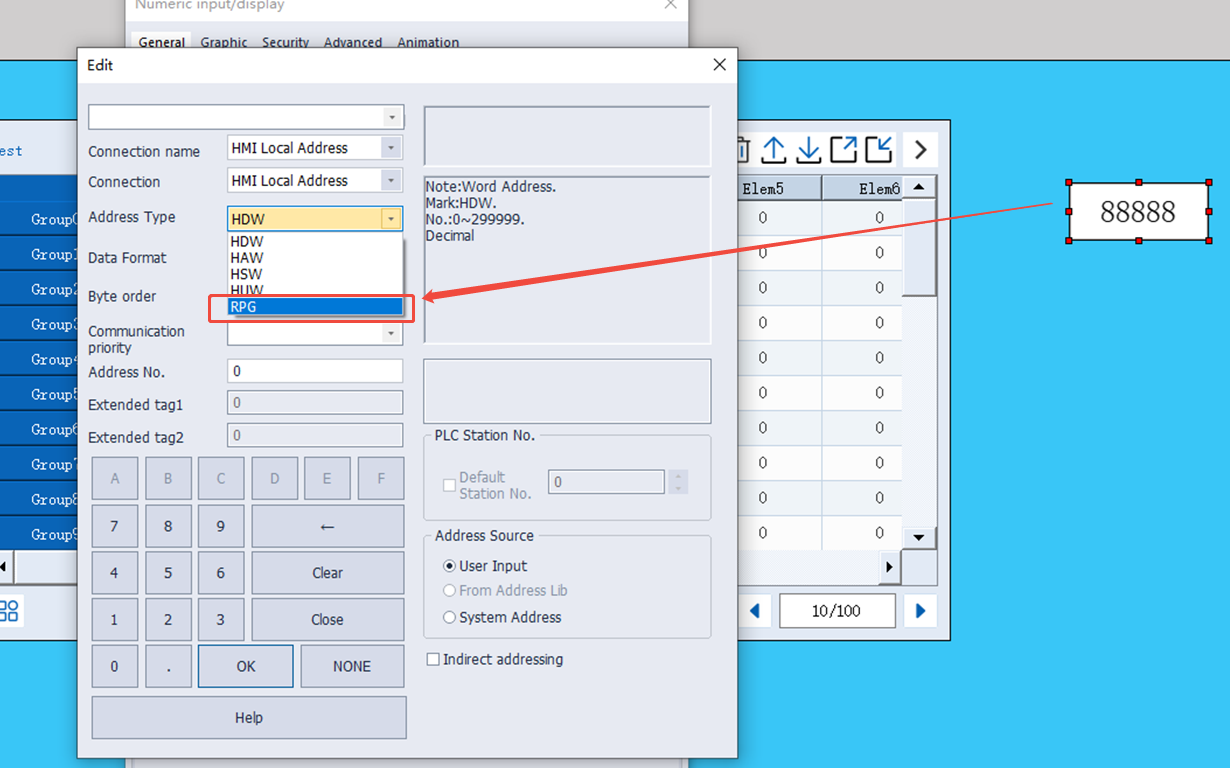
New recipe function address
In recipe, new special address is used as Function address.
Address Type: RPG
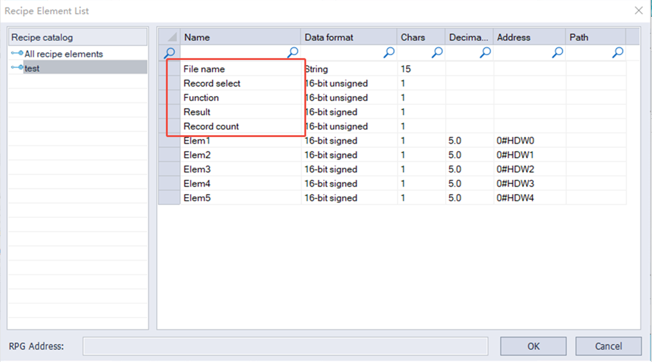
| Name | Data format | Length | Function |
| File name | String | 15 word address | Input file name |
| Record select | 16-bit unsigned decimal | 1 word address (0-65535) | Currently selected record, numbered starting from 0. When the record selection value changes, the corresponding value will be updated. |
| Function address | 16-bit unsigned decimal | 1 word address (0-65535) | Enter a specific value to send a command to the selected record "1": Add a new recipe record "2": Delete the selected recipe record "3": Upload the recipe "4": Download the recipe "5": Update the selected recipe record |
| Result | 16-bit unsigned decimal | 1 word address (-32768--32767) | View the result of executing the command. Display "1": Successfully executed the command Display "2": The record limit has been reached and no new records can be added. Display "4": No corresponding option Display "8": unknown command Display "16": recipe download failed. Display "32": recipe upload failed. Display "64": recipe update failed. |
| Record count | 16-bit unsigned decimal | 1 word address (0-65535) | Display the number of records in the current recipe |
| Element address | 16-bit unsigned decimal | 1 word address (0-65535) | Element address |
Traditional recipe
Traditional recipe is composed of multiple groups of information with the same structure and different data. Due to the similarity of these information, you could edit them into a set of recipes to facilitate the transfer of data between HMI and PLC.
Traditional recipe function is valid only when the LEVI project is converted to the PI project, and the original project uses the traditional recipe.
Simple recipe mode
Click the "Traditional Recipe"  in the "Data tool" bar in the upper side of the software, and the following interface will pop up:

✎Note:
- The recipe folder name can only consist of (0~9), (a~z), (A~Z), ('_'), ('').
- The element name of the recipe cannot include following 5 special characters: " , " , " | " , " < " , " > " , " & " .
Recipe display
Select the file type "Traditional recipe file" in object "Recipe Display", and it is recommended to fill in the traditional recipe group number HSW1612 to the address of select line.

Recipe transmission address
The special addresses used in the Recipe are shown in the following table:
| Address | Description | Function |
|---|---|---|
| HSW1611 | Traditional Recipe transfer operation. | =1: Recipe download. =2: Recipe upload. |
| HSW1612 | Traditional Recipe group number. | Traditional Recipe group number. |
HSW242 | Recipe operation result prompt: Upload: Data is written to recipe file from address. Download: Data is written to the address from recipe file. | =1: Recipe download, start. =2: Recipe download, execution error. =6: Recipe download, successful. =7: Recipe upload, start. =8: Recipe upload, execution error. =11: Recipe group name does not exist. =12: Recipe upload, successful. |
Recipe index
The recipe index address RPW is mainly used for editing traditional recipes, and it is more convenient to modify the data and display of recipes. Only need to modify and display the data of the recipe file through "Numeric Input/Display" Object and "Word Switch".
The recipe index area (RPW)'s instruction as follows:
- RPW**####, a total of six digits, the first two ** represent the Recipe group number, #### represents the element order number. For example, RPW010000 indicates the 1st element of the Recipe group No.1, and RPW110002 indicates the 3rd element of the Recipe group No.11.
- If the indexed group number or element number does not exist, the value of RPW defaults to zero. For example, RPW110011 represents the 12th element of the Recipe group No.11. If it does not exist, the value returned by accessing RPW110011 is zero. The value written in RPW110011 will not be saved to the recipe file.
- ✎Note: As long as RPW**#### exists, any object "writes" to HPW**#### will be saved to the recipe file.
- The RPW register only supports word address access.
- It can be known from the coding method of RPW**#### that the range of RPW is from RPW000000-RPW990450, wherein the range of group number is 0-100, and the range of element is 0-450.
Recipe example
The recipe index makes the modification and display of recipe data more convenient. Only need to modify and display the data of the recipe file through "Numeric Input/Display" Object and "Word Switch".
Edit the recipe configuration, create three groups of recipes, 4 elements for per group: Red, green, blue, spraying time, as following shown:

RPW 0~3 can display the data of group for the selected line. RPW10000~10003, RPW20000~20003, RPW30000~30003 each address can display the single element. Directly modify the content of the RPW address and then modify the recipe data, as following shown:

After selecting the 2nd group, trigger the download button to download the whole group data to the corresponding element address (For this case, the data will write into HDW0~3), or trigger the upload button to upload the content of the element address to the specified recipe group.

Trend chart
Trend chart function is used for displaying the real-time data in HMI as curve graph, which X axis represent as time, Y axis represent as data.
Click "Project" → "Trend chart", it will pop up the following screen. Click "Add" to creat new curve record.

Settings

(1) Basic settings
- Curve NO.: It is for setting curve number,
- Curve Name: It is for setting curve name. The length limitation is 31 bytes.
- Curve (1~8): It is for setting the number of curves. The default is 3.
- Dots of one curve: It is for setting dots number of each curve. The default is 1000, but the maximum dots are 10,000 for all the curves.
(2) Sample Type
- Sample method: There are two types, one is Cycle sample, the other is Trigger cycle sample. If you select Trigger cycle same mode, the trigger sample address is required to edit.
- Sample unit: 100ms.
(3) Quick Setting
- Data format: It is for setting all the curves, select the data format for all curves, and setting the reading addresses for curves. There are as follows.

- Sample address: Fill in the start address that read the device data. If the sampl address is consecutive, check "use continuous address". For example, set HDW0 as start address, curve number is 3, then the HDW0 is for Curve 1, HDW1 is for Curve2, HDW2 is for Curve 3.
(4) Curve Table: The sample address you have set would display on it. Click the corresponding box to modify the content.
Trend Chart Demo Download Link
https://drive.google.com/open?id=1smnaAvSxOWC0WQK4_uvqHXWn4vUZxGJC
History XY plot
Different from TrendChart, uses need to set history XY curve items in project. Please click "Project"-> "History XY Plot" to open the setting screen.
Recipe function settings will be display in "History XY Plot" object.


(1) Basic settings
- Curve NO.: It is for setting curve number,
- Curve Name: It is for setting curve name. The length limitation is 31 bytes.
- Curve (1~8): It is for setting the number of curves. The default is 3.
- Dots of one curve: It is for setting dots number of each curve. The default is 1000, but the maximum dots are 10,000 for all the curves.
(2) Sample Type
- Sample method: There are two types, one is Cycle sample, the other is Trigger cycle sample. If you select Trigger cycle same mode, the trigger sample address is required to edit.
- Sample unit: 100ms.
(3) Quick Setting
- Data format: It is for setting all the curves, select the data format for all curves, and setting the reading addresses for curves. There are as follows.

- Sample address: Fill in the start address that read the device data. If the sample address is consecutive, check "use continuous address". For example, set HDW0 as start address, curve number is 3, then the HDW0 is for Curve 1, HDW1 is for Curve2, HDW2 is for Curve 3.
(4) Curve Table: The sample address you have set would display on it. Click the corresponding box to modify the content.
Operating Procedure
- Click "Project" → "History XY Plot" to open the function selecting windows.

- Click "Add" button to open "History XY Plot” setting windows.

- Setting the function of History XY Plot.
- Click "OK" to save the setting.
Download Link
https://drive.google.com/open?id=1t4_HuRmIJJ-B5ryA2kVMadD9FywKhZ4r
Data record
The data record function is organized according to the structure below. In a project, there can be multiple record groups, each record group containing multiple channels. Different groups have different sampling times.
The topology is shown in the following figure.

The data record stored in SD card is also organized according to the above figure.
The sample time and save time is consistent in the same record group. There are multiple channels in the group, When the sampling time is up, every channel would collect data to PLC register according to its own address.
Sampling interval: The interval between two consecutive samples was recorded.
As long as the project uses the data record function and supports the large-capacity storage module, the system will sample data according to the set sampling interval and save data according to the set saving interval.
For the file storage of data, see the file size configuration during data record configuration.
✎Note:
After enable the Cloud and check the box of Upload to Cloud, the communication port settings of the address in the imported Data record configuration must be the same as the communication port settings of the current project, otherwise it cannot be used normally.
The number of Data records upload to Cloud shall not exceed the limit value, or the sum of the imported Data records and the number of existing alarm records shall not exceed the limit value. the specific limitation as following table:
| Series | Number of Data Record upload to Cloud |
|---|---|
| 8000-R | 100 |
| 9000-R | 100 |
| 3000ig | 50 |
| 8000ig | 100 |
| MD | 50 |
The record group name can only be composed of Chinese characters, (0~9), (a~z), (A~Z), ('_'), ('') and other non-English characters.
Channel name cannot incloud following symbols: :" , ", " | ", " < ", " > ", " & ".
Settings

Operating Procedures
- Click "Project"->"Data record" as below shows.
- Click "Add" button to open "Data record" setting window.
- Enter group name, the default is "GroupName0"
- Select "Trigger function" mode, such as "No trigger".
- Set "Total channels", such as 3.
- Click "Apply" button.
- Set Sample cycle, such as 15.
- Set "Start channel" in "Quick settings", such as 4 0.
- Check group information in "Channel list" as below.
- Click "Save" button to complete settings.
The figure above display the group of current project. The data record file would stored in "DataLogFile" folder, and the data of every group would have a data file. The file suffix is in "db" format.
✎Note:
- For HMI series 8000 and above, the size of a single file cannot exceed 300M and the total file capacity cannot exceed 1000M.
- For HMI series 3000, the size of a single file cannot exceed 4M and the total file capacity cannot exceed 10M.
- If the total amount exceeds the range, an alarm will be given during project compilation.

(1) Group name: Set group name, and he name should be unique.
(2) Trigger function: There are four modes to trigger record.
- No trigger: Data will be recorded in every sample time.
- Trigger to record by sample cycle: Data will be recorded in every same time, when trigger control bit set ON.
- Trigger to record once and reset: Data will be recorded when trigger control bit set ON, and the bit will be reset automatically.
- Trigger to record once: Data will be recorded when trigger control bit set ON, and the bit need to be reset manually.
- Trigger address: It is only valid when the trigger condition is selected. The monitoring cycle for trigger sampling address is 1s.
(3) Total channels (1~100): Set the numbers of channels. Click "apply" to view the channel lists on the right record channel.
(4) Sampling cycle: If you check "collect control address", the sampling interval is the value of the address. The unit is second. For example, Sample cycle=15s. It means that records data one time every 15s.
Timing address: It sets address to change sample time when HMI is running;
(5) Total records: It sets data record number in one data record file. If the data file size is beyond the current file size. The old data will be deleted, and the new data will replace the old data. Please remember to back up the old data record file.
Abnormal value: It sets a value, when communication fails, data record will record this value;
(6) Upload to Cloud: The data uploaded by Data Record is stored in the Cloud(Only ig series). The maximum number of record is 20.
(7) Quick Settings
- Start Channel: It sets the continuous addresses for channels.
- Data Format: It sets the same data format for channels.
- Number of Digits: It sets the digits’ number for channels.
- Language Settings: The text in HMI can be in 8 languages, user can set language in here.
(8) Channel List: Besides quick settings, user can set channel name, address, data format, and so on one by one according to real situation.
✎Note:
- After enabling the Cloud function and checking the upload to the Cloud, the communication port settings of the address in the imported Data record configuration must be the same as the communication settings of the current project, otherwise it cannot be used normally.
- The range of upload to the Cloud from Data record configuration must not exceed 50, or the total number of imported Data records and the number of currently existing Data records must not exceed 50. If it exceeds, it will prompt you to reconfigure, should reduce the number.
- The channel name can only be composed of English characters, (0~9), (a~z), (A~Z), ('_'), ('').
- The channel name does not include these 5 special characters: ", ", "| "," <", "> "," & ".
- The data would be overwritten automatically if the capacity exceed the maximum capacity. For 8000/9000 series, the size of single file cannot exceed 300MB, and total capacity of data records cannot exceed 1000MB. For 3000/3000i/3000ie series, the size of single file cannot exceed 4MB, and total capacity of data records cannot exceed 10MB. If the total amount exceeds the range , an error will be prompted when the project is compiled.
You could click here to jump to object "Data Record Display"
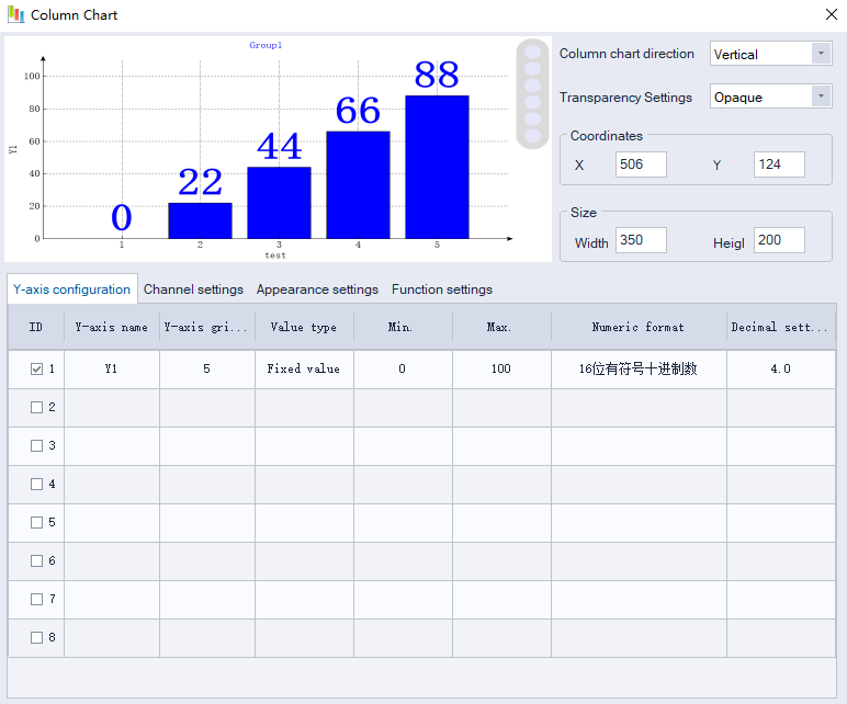
Column Chart
Use the bar chart to monitor and visualize register data in real time
Y-axis configuration
Configure the Y-axis parameters, including value type, minimum ,maximum ,data types, and decimal point settings.
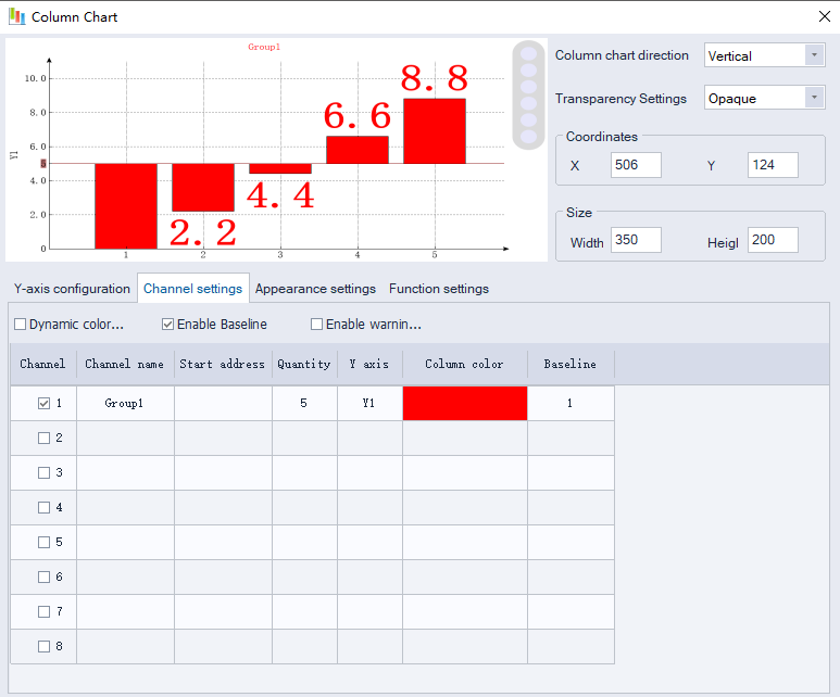
Channel setting
Set the channel address to be displayed.
Dynamic color: Change value of a word address to change the color of the channel display.
Dynamic color sequence: The color sequence number bound to the channel (click to enter the color sequence configuration interface)
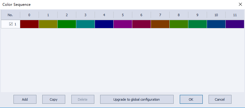
Color sequence configuration interface
Upgrade to Global Configuration: This color sequence is upgraded to the global default.
Global Configuration: When a new bar chart control is created in a project, the color sequence has a default configuration. When you upgrade an existing configuration to a global configuration, the default color sequence for the new control will be the same as the configured color sequence.
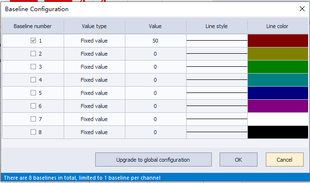
Enable Baseline: Set baselines on the bar chart.
Baseline: The baseline ID bound to the channel) (click to enter the baseline configuration interface).
Baseline Configuration:
Value type: Baseline value type
(Fixed value: baseline value is fixedly set; Dynamic address: baseline value is read from address).
Upgrade to Global Configuration: This will make this warning zone the global default configuration.
Global Configuration: When a new bar chart control is created in a project, the warning zone has a default configuration. When you upgrade an existing configuration to a global configuration, the default configuration for the new control will be the same as the configured one.
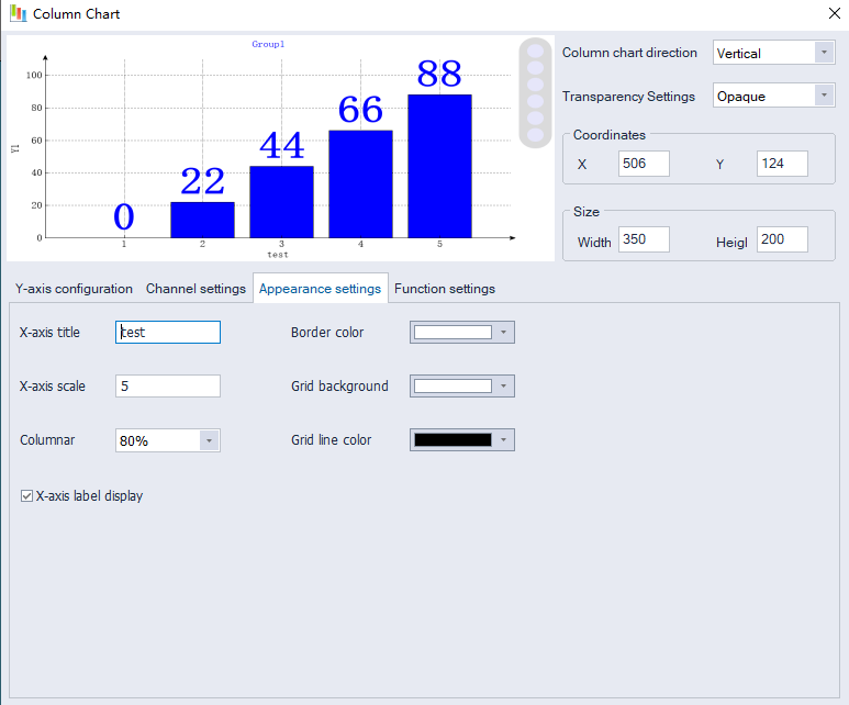
Appearance setting
Set a configuration for the X-axis, background color, etc.
Function settings
Column Update Method:
Periodic Update: Updates the histogram periodically.
Triggered Update: Controls whether the histogram updates based on an address.
Triggered Periodic Update: Triggers a periodic update of the histogram.
Cycle update time: Periodic update time setting, unit: seconds
Function control starting address: The function of the bar chart can be controlled by the address. The starting address is configured here. For specific functions, refer to the address description list.
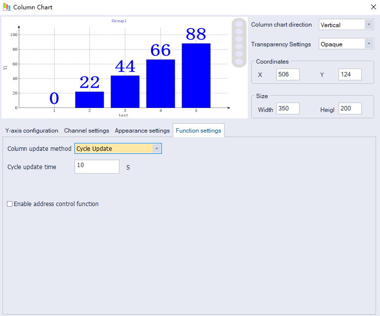
Chart Button

:Menu
:Zoom in
:Zoom out
:Restore button (Reset the chart's zoom level to its original 1:1 ratio)
:Data label hide/show button(Controls hiding/showing of data labels)
:Settings Button
User permission
Introduction
- User permission is one of expansion function in PI Series HMI; it provides multi-level of permission for control HMI operations.
- User need to set the user and group during designing project. Different groups have different permission levels for accessing. Each user should be added into the specified group; it is possible to add the same user into different groups.
- Operating record: it records user operations information, the records files are saved in HMI flash; its path is [\\flash\\UserOperationLogs.db].
- When it is on simulator mode, the files are saved in C disk, its path is [C:\\WECON\UserMgrFile\UserOperationLogs.db].
Settings
Open PIStudio software, then operate as the following figure.

Click on the cell from UserName and Desc, which can support the multi language.

- Click "User Permission" in "Data Tool" toolbar.
- Edit user name, click "User0" cell under "UserName", and then enter the user name, one project allows maximum 20 users.
- Edit password, click "User0" cell under "PassWord", and then enter the user name.
- Edit description, click "User0" cell under "Desc", and then enter, description is not necessary。
- Check the groups for each user, there are 11 groups beside admin.
- Editing groups' description, but it is not necessary.
- Click "Save and Exit" button to complete all settings.
Object permission configuration

User operation logs support multi languages configuration. Click on the Log Message, the text editor of multi language will be pop up:

Operation Procedure of Object Permission
- Open the object setting windows;
- Select "Security" windows;
- Check the "User Permission";
- Select "Level" to set permission level;
- Enter "Log Message", it is for operation records, if it was empty, the operation for this object would be not be recorded;
- Select the "Access Denied Setting" mode;
Log information description
A combination of Chinese characters, numbers, and uppercase and lowercase letters can be entered, and the number does not exceed 63.
The format of insert variable:{variable address, data format}. e.g., {HDW100,UW2.1}.
The data format are as follows.
| Letter | Meaning |
|---|---|
| B | Binary |
| O | Octonary |
| U | Unsigned decimal |
| H | Hexadecimal |
| b | BCD |
| F | 32-bit float |
| S | Signed decimal |
| C | Character |
| W | Single word |
| D | Double word |
Examples.
- Unsigned decimal, BCD, 32-bit float and Signed decimal are as follows.
{HDW100,UW2.1}: Indicates the variable address is HDW100. The data format are: unsigned decimal, single word, two integer bits, one decimal place.
Binary, Octonary and Hexadecimal are as follows.
{HDW100,HD8}: Indicates the variable address is HDW100. The data format are: hexadecimal, double word, eight integer bits.
Character is as follows.
{HDW100,C32}: Indicates the variable address is HDW100. The data format are: 32 characters.
When a record is generated, the contents of this variable are replaced by the value of your corresponding address.
Function address
A user must first log in before performing an operation, and after the login is successful, the user can perform the required operation, and log out after completing the operation, making the operation permission invalid. User login, log out, modification of user password during operation and user management and other functions need to be configured.
HMI allows managing user accounts on screen. Including adding, deleting and editing the user account. HMI provide built-in screen for [Sign in] and [change password] (screen No. 1006 and 1007).
Functions and addresses are as follows.
| Function | Address | Object type | Address function |
|---|---|---|---|
| Sign in | HUW1158~1335 | Drop down list | User name |
| HUW1002 | Character input object | Password | |
| HUW1000 | Word Switch (Input 1) | OK (sign in) | |
| Change password | HUW1158~1335 | Drop down list | User name |
| HUW1002 | Character input object | Old password | |
| HUW1006 | Character input object | New password | |
| HUW1010 | Character input object | Confirm password | |
| HUW1000 | Word Switch (Input 2) | OK(change password) | |
| Sign out | HUW1000 | Word Switch (Input 3) | Sign out |
New user *1 | HUW1014 | Character input object | User name |
| HUW1006 | Character input object | password | |
| HUW1010 | Character input object | Confirm password | |
| HUW1000 | Word Switch (Input 4) | OK(add new user) | |
| HUW1336~1345 | Character input object | User description | |
| HUX1347.0 | Bit switch | =1: User hidden =0: Visible (Defaults) | |
| HUW1000 | Word Switch (Input 8) | Save(add Hide features) | |
Delete user *2 | HUW1158~1335 | Drop down list | User name |
| HUW1000 | Word Switch (Input 5) | OK (delete user) | |
| Delete Profile | HUW1000 | Word Switch (Input 9) | OK(delete) |
| Export Profile | HUW1000 | Word Switch (Input 10) | OK(export) |
| Import profile | HUW1000 | Word Switch (Input 11) | OK(import) |
| Export log file | HUW1000 | Word Switch (Input 12) | OK(export) |
| Delete log file | HUW1000 | Word Switch (Input 13) | OK (delete) |
| Current user name | HUW1349 | Character object | 32 Word |
| System state information | HUW1030 | Character input object | System state information |
| Permission settings | HUW1014 | Character input object | User name |
| HUW1348 | Bit switch | Set the user group: HUX1348.0 = 1 administrator; HUX1348.1 = 1 group 0 permission; HUX1348.2 = 1 group 1 permission; (Total group 0 - group 10) | |
| HUW1000 | Word Switch (Input 6) | Add user rights (set according to HUW1348) | |
| User login mode setting | HUW1382 | Word Switch/Numeric input object | 0: Select a user name from the drop-down list 1: Use character input object (address HUW1014) to log in with a user name |
When the user performs a function operation, the operation result is displayed in the HUW1001.
| Value (HUW1001) | Meaning |
|---|---|
| 1 | Insufficient permissions. |
| 2 | Username does not exist. |
| 3 | Username already exists. |
| 4 | Wrong username or password. |
| 5 | Login successfully. |
| 6 | Passwords are inconsistent in twice time. |
| 7 | Password changed successfully. |
| 8 | User added successfully. |
| 9 | User deleted successfully. |
| 10 | Maximum number of users exceeded. |
| 11 | Admin user already exists. |
| 12 | User permission modified successfully. |
| 13 | File imported successfully. |
| 14 | File imported failed. |
| 15 | File exported successfully. |
| 16 | File exported failed. |
| 17 | Logout successfully. |
| 18 | Profile deleted successfully. |
| 19 | Log file deleted successfully. |
| 20 | Hide settings modified successfully. |
| 21 | Hide settings modified failed. |
| 22 | Password already occupied, please reset. (For both username and password, it can not repetition) |
User Permission Demo Download
https://drive.google.com/open?id=1qOiEDvo_1H1YqpoLDpS77dGaAFm8nrGq
Message prompt
A message box is a window used to show some prompts or warnings to users. For example, the application process a task in the process of pop-up message box, suggesting that "U disk has been detected", then the customer can carry out data dump function.


(1) Message
It includes system classes (u disk, SD card, and others), chart classes (alarm, data record, recipe, file list), curve classes (Trend Chart, historical XY trend Plot).
(2) Control
- Current item: It shows selected message information.
- Use trigger address: When the message is triggered, the trigger address would be set ON.
For Example:
Trigger address is 011, during inserting a USB flash disk into HMI, and 011 would be set ON, once HMI recognizes USB flash disk, and display message.
- Show message: Check it to display message when HMI is running. It is checked by default.
- Show on web: Check it to display message when remote access HMI screen, it is unchecked by default.
(3) Message Content
Each message has default content, but you could set different content according to the actual situation. And the same message could be displayed in 8 languages.
(4) Reload Text: It means discard changes.
For Example
User deletes default content or modifies default content, but he wants to give up modification back to original, just click "Reload text".
Appendix
The following pop-up message and code only available for HMI System V1.0, to indicate some system errors:
| Message code | Description | |
|---|---|---|
| 10001 | Failed to delete folder directory | First confirm whether the U disk SD card is read-only, or if there are other abnormalities, if it cannot handle by prevouis advises, please provide the back label and background version info. |
| 10002 | Failed to renaming file | |
| 10003 | Failed to delete file | |
| 10004 | Inconsistent data record tables | The files in the U disk SD card may be from other projects, or the same project but the number of channels in the current project is inconsistent with the record. Please consider verifying it first. |
| 10009 | LAN monitoring error | Data packet loss during the monitoring process may cause this problem. Confirm the software version. The company has updated this issue. Older versions can be updated |
| 10010 | ||
| 10011 | ||
| 10012 | ||
| 10015 | Failed to initialize project | It is recommended to send the project back to the company for testing |
| 10022 | U Disk Safe Exit Failed | It may be in use, data is exported, or the storage location is U disk or SD card. It is best to trigger again and wait for its successful exit. |
| 10023 | SD card safe exit failed | |
| 10024 | U disk is busy | |
| 10025 | SD card is busy | |
| 10026 | Cannot recognize the U disk/SD card | |
| 10027 | U disk/SD card cannot be read or written | Detect the format of U disk/SD card. Fat32 and ntfs can be recognized normally. If the computer can use it normally and the HMI cannot recognize it, you can only consider formatting the U disk first and then try again. |
| 10028 | U disk/SD card unknown error | |
| 10029 | U disk/SD card format error | |
| 11000 | Alarm record error | The version before Sept. 19th considers the flash problem. Please provide the back label and the backstage version info . Make sure to ask the customer to update the version first, and the customer's similar projects must be updated even if there is no problem. After the update, the flash usage should be checked and. If the flash is on a severe status, return to the company replaces the flash with a new one. When the question is returned, the text behind the prompt is as complete as possible, which can help R&D to confirm the problem faster. |
| 11001 | ||
| 11002 | Failed to delete Alarm record in Flash | |
| 11006 | Failed to save the Alarm records to Flash | |
| 11007 | Alarm record error | |
| 11009 | Data record error | |
| 11010 | ||
| 11011 | Failed to save Data records to Flash | |
| 11012 | Failed to delete Data record in Flash | |
| 11013 | Data record error | |
| 11014 | Failed to transfer Data record to U disk/SD card | |
| 11015 | Failed to copy Data record to U disk/SD card | |
| 11016 | Data record error | |
| 11017 | User permission related operation error | |
| 11018 | SQL trigger monitoring error | |
| 11019 | Data record error | |
| 11020 | Historical XY graph error | |
| 11021 | Failed to save the Historical XY graph to Flash | |
| 11022 | Failed to delete the Historical XY graph in Flash | |
| 11023 | Installment payment error | |
| 11024 | ||
| 11025 | ||
| 11026 | ||
| 11027 | ||
| 11028 | Real-time trend graph error | |
| 11029 | ||
| 11030 | ||
| 11031 | Failed to delete the Real-time trend graph data in the memory | |
| 11032 | Failed to save the Real-time trend graph to Flash | |
| 11033 | Recipe error | If it is a new project download and there is an error, first confirm the settings of the recipe, if it is abnormal after a period of use, confirm whether it is the flash problem |
| 11034 | ||
| 11035 | ||
| 11036 | ||
| 11037 | ||
| 11038 | ||
| 11039 | ||
| 11040 | ||
| 11041 | ||
| 11042 | ||
| 11043 | ||
| 11044 | ||
| 11045 | ||
| 11046 | User permission related operation error | If an error occurs when downloading a new project, first confirm the permission configuration, whether the reserved configuration is checked in the download tool, etc., if it is abnormal after a period of use, confirm whether it is a flash problem |
| 11047 | ||
| 11048 | ||
| 11049 | Failed to upload operation log file via Ethernet | |
| 11050 | User permission related operation error | If an error occurs when downloading a new project, first confirm the permission configuration, whether the reserved configuration is checked in the download tool, etc., if it is abnormal after a period of use, confirm whether it is a flash problem |
| 11051 | ||
| 11052 | ||
| 11053 | ||
| 11054 | ||
| 11055 | ||
| 11056 | ||
| 11057 | ||
| 11058 | Alarm record error | Same as flash problem |
| 11062 | Installment payment error | |
| 11063 | Alarm Runbar error | Mostly, the Runbar is used without config the alarm settings. |
| 11069 | Historical trend graph error | Same as flash problem |
| 11070 | ||
| 11071 | ||
| 11072 | SQL trigger monitoring error | |
| 11073 | Real-time trend graph error | Same as flash problem |
| 11075 | Error getting database table file | Same as flash problem |
| 11076 | Error getting database table file | Same as flash problem |
| 11077 | Recipe error | If it is a new project download and there is an error, first confirm the settings of the recipe, if it is abnormal after a period of use, confirm whether it is the flash problem |
| 11078 | ||
| 11079 | ||
| 11080 | User permission related operation error | Same as 11046 |
| 11081 | ||
| 11082 | Drop-down list error | |
| 11083 | The message prompt error | |
| 11084 | Alarm record error | Same as flash problem |
| 11085 | ||
| 11086 | Data record error | Same as flash problem |
| 11087 | ||
| 11088 | Alarm record error | Same as flash problem |
| 11089 | ||
| 11090 | Installment payment error | Same as flash problem |
| 11091 | The message prompt error | |
| 11092 | The database table file does not exist | |
| 11093 | Machine code error | |
| 11094 | Import csv file error | |
| 30001 | Flash free space is not enough to store Data records | Insufficient space, whether any file is copied into the flash |
| 30002 | Flash free space is not enough, Historical XY trend graph is not stored | |
| 30003 | Flash free space is not enough to store real-time trend graphs | |
| 30005 | System read only | Same as the flash problem, if the flash is damaged, then the system must be updated |
| 30006 | Insufficient reserved blocks |
Cloud
Introduction
You may configure the basic settings of Cloud functions, tags, and User MQTT according to your needs. (If the device supports the Cloud function, you can use the function and configure the tags after checking the box to enable it, or upload the data to the 3rd party server.)
Click "Project"-"![]() Cloud" in the upper left corner of the software, as shown in the following figure.
Cloud" in the upper left corner of the software, as shown in the following figure.

(1) Enable
If the HMI supports the Cloud function, check it to enable the Cloud function, and it will collect the real-time data from HMI upload to the Cloud. The number of data collection is limited, and the specific parameters are as follows:
| Series | Monitoring Tags | Alarm Record | Data Record | OpenCloud Data |
|---|---|---|---|---|
| 8000-R (HMI V2.0 System) | 300 | 200 | 100 | 1000 |
| 9000-R (HMI V2.0 System) | 300 | 200 | 100 | 1000 |
| 3000ig | 100 | 20 | 50 | 500 |
| 8000ig | 300 | 200 | 100 | 1000 |
| MD | 100 | 20 | 50 | 500 |
For example:
- In 3000ig's Cloud, the monitoring tags upload to the Cloud in real time is limited to 100.
- For 3000ig's Alarm, the Alarm records of word alarms and bit alarms upload to Cloud is limited to 20. (See "Alarm" for details).
- For 3000ig's Data record, the Data records upload to Cloud is limited to 50. (For details, please refer to "Data Record").
(2) Server Selection
Server: China, ASEAN, and Europe.
Password:
- If the HMI is not bound, this access password will be updated and downloaded into the HMI screen simultaneously.
- If the HMI is bound, this access password in the project cannot effectively change the binding password of the device, and it can only be changed through V-NET.
(3) Upload Selection:
To upload the data collected by HMI to the cloud or a to the third-party server, only one upload method can be selected.
- to Cloud: All the configured tags, data records, and alarm records would be pushed to V-NET.
- to User MQTT: All the configured tags, data records, and alarm records would be pushed to to the third-party server, and the relevant Lua function calls please refer to "Cloud interface".
After the "to User MQTT" is checked. The tags, data records, and alarms cannot be viewed on V-NET, but the device can be bound to V-NET and remote monitoring the device screen normally.
4) Low Data Mode setting
- When you check the "low Data Mod" by default on new tags, the newly added tags will be enabled in Low Data Mode by default.
- The longer the refresh interval, the slower the data upload, and the more traffic data will be saved. This function is only used for the control of tags.
MQTT
Configurable type MQTT. Users can publish message to the MQTT server or subscribe topics from the MQTT server.
The supported models and series are listed in the following table:
| Support series |
| 3000ig |
| 8000ig |
MQTT Configuration (Common Settings/AWS IOT Settings/ALi Settings/Huawei Settings)
This chapter explains how to use configurable type MQTT. Users can publish message to the MQTT server or subscribe topics from the MQTT server.
Click “MQTT” in “Data Tool" in the upper side bar of the software.After checking "Enable", the settings window will pop up and select different cloud services for MQTT configuration, as shown in the following figure:

MQTT Server Settings (Common)
General

Description: Enter a description or comment about the server. Maximum input length: 255 characters, cannot be empty.
Cloud Service: (Select Common)
① Common (Common Platform): General MQTT publish-subscribe topic mode.
② AWS IoT (Amazon): Using "AWS IoT" as the Broker, using Thing to transfer data and support Shadow function.
③ ALi (Alibaba Cloud): Using "Alibaba Cloud" as Broker.
④ Huawei (Huawei Cloud): Using "Huawei Cloud" as Broker.
Communication protocol: MQTTv3.1, v3.1.1 and v5 are supported.
Custom Client ID length: User can customize the length of the Client ID (optional), length range: 20 ~128.
Custom username/password length: Customize the length of user name/password length (optional), length range: 16 ~ 256.
IP: Set the MQTT server IP to subscribe message.
Use domain name: Support using domain name to the specify server.
Domain name: Set the domain name of the MQTT server that subscribe message. Maximum input length: 128 characters, cannot be empty, supports letters, numbers, "-", “.”. The symbol cannot be placed at the first character or last character of name.
Port number: Set the MQTT server port to subscribe message. Range: 0~65535, cannot be empty.
Client ID: Login name. Variables can be used as login names. For example: Enter% 0 and the Client ID is the device name. (This can be set in the HMI background. If not, the default is HMI model.) (✎Note: A Client ID can only be used for one device.) When there is no custom Client ID length, the maximum configurable length of Client ID is 40 characters.
Verification: Choose whether to connect to the MQTT server using [User Name] and [Password].
User Name: The [User Name] connects to the MQTT server. When there is no custom username/password length, the maximum configurable length of username is 32 characters.
Password: The password for connect to the MQTT server. When there is no custom username/password length, the maximum configurable length of password is 32 characters.
Timestamp: LOCAL: Using the HMI time as the timestamp. UTC Time: Using UTC+0.
Clean message cache when normal connected: If option is enabled, when the device is disconnected, the message to be published will be cached in the cache area, and then will be published when the device is online again.
Address

Status address: (Total length: 2 words)
HDWn: Display [MQTT] connection status.
| Value | Description |
| 0 | Disable MQTT server connection |
| 1 | Disconnected or connecting |
| 2 | Successfully connected the MQTT server |
HDWn+1: Error prompt
| Value | Description |
| 0 | No error |
| -1 | General error code of wrong operation |
| -3 | Disconnected |
| -4 | Exceed client data concurrency |
| -5 | Invalid UTF-8 string |
| -6 | Null pointer parameter |
| -7 | Topic name is truncated |
| -8 | Wrong protocol structure body |
| -9 | Bad QoS, acceptable range is (0, 1, 2) |
| -10 | Try to use a non-SSL version library for SSL connection |
| -11 | Wrong MQTT version |
| -14 | Wrong protocol type |
| -15 | Option is not suitable for the current request version |
| -16 | Call MQTT version that is not applicable to request. |
| -17 | 0 length connects topics |
Buffer usage address: (Total length: 1 word)
Unsuccessful published message will be stored in memory as cache, with a maximum 100,000 messages or 2M. Value display as unit %, and it is carried unconditionally.
HDWn: Display buffer usage.
Control address: (Total length: 123 words; If the domain name is not enabled, it will take up 59 words)
HDWn: Control the execution or stop of [MQTT Server].
| Value | Description |
| 0 | Ready |
| 1 | Start |
| 2 | Stop |
| 3 | Update |
HDWn+1: IP address of the MQTT server. (✎Note: This address is only valid when IP is used.)
HDWn+5: Port number of the MQTT server.
HDWn+6: Client ID of the MQTT server connection.
HDWn+26: Authentication is enabled or not. = 0, disabled; = 1, enabled.
HDWn+27: User name of MQTT server connection.
HDWn+43: Password of MQTT server connection.
HDWn+59: Domain name of the MQTT server. (✎Note: This address is only valid if the domain name is used.)
TLS/SSL Settings

Enable: Enable TLS/SSL encryption. User can manually select encrypted versions of TLS 1.0, TLS 1.1, or TLS 1.2.
Server authentication:
Enable: Verify whether the server certificate has been certified by a Certificate Authority Certificate (CA). Server certificates are sent by the server when connection is established.
Import: Select CA certificate to import.
More: After the import is successful, clicking it will display the certificate details.
Reset: Reset the import information.
The server name must match the certificate information: Verify whether the server name or IP matches with the information in the certificate. Domain name and IP are recorded in the Subject Alternative Name from certificate.
Client authentication: The private key and client certificate are the data required for the server to authenticate the client end.
Certificate:
Import: Select certificate to import.
More: After the import is successful, clicking it will display the certificate details.
Reset: Reset the import information.
Key:
Import: Select the key to import.
More: After the import is successful, clicking it will display key details.
Reset: Reset the import information.
System topics

Birth Topic: The message that HMI will publish when it is connected to server.
Close Topic: The last send message before HMI actively disconnects from server connection
Last Will: Subscription of Last Will receive this message when an abnormal disconnection occurs between HMI and the server. HMI synchronizes the Last Will message to the server when it initially establishes the connection.
Topic List: A list of topics in the HMI that is sent to the server after the HMI is connected to the server.
Topic: The actual topic name of the system topic. Maximum input length: 255 characters, cannot be empty.
Retain message: The MQTT server keeps the latest message.
QoS: MQTT provides three levels of reliability called service quality. The service quality of message transmission determines whether the message is guaranteed to be delivered.
QoS 0: Messages are sent only once, and delivery is not guaranteed.
QoS 1: Message must be delivered at least once.
QoS 2: Message is delivered just once.
Content format:
JSON (Default): Use default values, default values for each system topic (The bold is represented as the current actual value)
Birth Topic:
{
"d": {
"connected": true
},
"ts": " Current time"
}Close Topic:
{
"d": {
"connected": false
},
"ts": " Current time"
}Last Will:
{
"d": {
"connected": false
}
}Topic list:
{
"d": {
"topics": [
{
"compression": "
",
"nickname": "Subject name",
"topic": "Theme"
},
{
"compression": "Compression type",
"nickname": "Subject name",
"topic": "Theme"
}
]
},
"ts": "Current time"
}
Messages within topics vary depending on the actual topic settings. The above is an example of two topics.
JSON (Customized): Use custom content.
Choose the connection network card

Default: According to the priority order of network adapters set in the HMI background to connect server.
Ethernet 1: Specify Ethernet 1 network card to connect to the server. When the system does not find Ethernet 1, connect to the server by “Default”. When system finds Ethernet 1 and binds it to connect to the server.
Ethernet 2: Specify Ethernet 2 network card to connect to the server. When the system does not find Ethernet 2, connect to the server by “Default”. When system finds Ethernet 2 and binds it to connect to the server.
4G: Specify 4G network card to connect to server. When the system does not find 4G, connect to the server by “Default”. When system finds 4G and binds it to connect to the server.
Wi-Fi: Specify Wi-Fi network card to connect to server. When the system does not find Wi-Fi, connect to the server by “Default”. When the system finds Wi-Fi and bind it to connect to the server.
MQTT Topic
MQTT topic publish
Select [Topic publish], click [Add], enter [Add MQTT topic publish object], and set the general settings and address. The maximum number of MQTT published topics is 255.

General properties

Alias: Set the project name of the MQTT topic. Maximum input length: 255 characters, cannot be empty.
Topic: The topic received by the MQTT server when sending message. Maximum input length: 255 characters, cannot be empty.
Sending mode: (AUTO/TRIGGER)
① AUTO value change mode: When any value changes, MQTT message is published.
a. Minimum time interval between messages: The minimum time interval can be set between messages to avoid over-publishing MQTT messages. When the interval of value change is less than the minimum time interval between messages, the message will be put in the cache. The MQTT message will not be published until the minimum interval between messages is met. Range: 0~3600000ms.
b. Periodic mode: Publish MQTT message by the fixed time. Time interval: Set the time interval for periodic publishing. The range is 1~3600s.
② TRIGGER
When the specified bit is triggered, the MQTT message is published. When HDX0.0 changes from OFF to ON, an MQTT message is published, and HDX0.0 is automatically set to OFF after publishing.
Compression type: Message is compressed before it is transmitted. The compressed message needs to be decompressed before the MQTT client reads it. Zilb, Gzip, or Deflate algorithm can be chosen to compress or decompress the message.
QoS: MQTT provides three levels of reliability called service quality. The service quality of message transmission determines whether the message is guaranteed to be delivered.
0: Messages are sent only once, and delivery is not guaranteed.
1: Message must be delivered at least once.
2: Message is delivered just once.
Retain message: When checked, the MQTT server keeps the latest message.
Content format:
Raw data: Data composed of BYTE data.
JSON (General): Put all data in JSON format of member "d".
JSON (Advanced): JSON format of flexibly customizable nested structure.
Include timestamps: This function is only supported when the content format uses [JSON (General)], and whether to include the timestamp can be decided manually.
Use the top "d" symbol in the message format:
This function is only supported when the content format uses [JSON (General)]. When checked, the message format is as follows:
{
"d": {
"addressName1": ...,
"addressName2":...
},
"ts":...
}
When unchecked, the message format is as follows:
{
"addressName1": ...,
"addressName2":...,
"ts":...
}
As shown above, when unchecked, ts and address names are both key at the same level. Therefore, avoid taking the address name as ts.
Address setting
①Address settings when content formats use [Raw Data] and [JSON (General)].

Add: Establish the address source of the topic. The length of each address can be set separately.
Delete: Delete the address.
Settings: Modify the address and name.

Included in all message sent
Check the options: This topic will include this address every time it publishes a message.
Uncheck the options: When the sending mode is value, message is published only when the value of the address changes.
Remove JSON array brackets' ['and'] ':
Check the options: Remove the array symbol name when using non-array bits or characters.
✎Note: A topic can be configured up to 255 nodes. The name length of a node can be configured up to a maximum of 255 characters and cannot be empty.
② Address setting when the content format uses [JSON (Advanced)]. [JSON (Advanced)] supports nested structure, which can use components, arrays and other forms. Timestamps and data names can also be customized, which is a more flexible design method.

The above figure is an example. If setting like above figure, the subscription side will receive the MQTT message like following format.
{
"object": {
"value": "teststring",
"value (1)": 123,
"value (2)": true,
"value (3)": "",
"value (4)": 0,
"value (5)": true
},
"array": [
10,
20,
30
],
"value (6)": " 2023-04-27T03: 53: 20.156271 "
}
New component: Add a new data component. Components can have multiple data formats; each data format has its own Name and Value. The data of the component is included in braces {}.
New value: Add a new value, string, or timestamp. When it is a value or a string, it can be fixed value or read data from a specified address.
Delete: Delete the selected field.
Settings: Modify the selected field. If the selected fields are components and arrays, only the names can be modified. But components and arrays include values that can modify parameters.
Template: Paste the JSON text here, and the system will automatically arrange the style to conform to this JSON format, saving the time of self-definition.
Preview: Preview JSON data in an easy-to-read format.
✎Note: A Topic can be up to 512 nodes (including payload), and a node name can be configured to be up to 255 characters length.
Security settings
The topic is published only when the register status matches the setting. As shown in the following figure, this topic will not be published until the address HDX0.0 is set to ON.

MQTT topic subscription
Select [Topic subscription] and click [Add] to enter general property settings and address settings. The maximum number of MQTT subscription topics is 255.

General properties

Alias: Set the project name of the MQTT topic. Maximum input length: 255 characters, cannot be empty.
Topic: Topics subscribed from the MQTT server. Maximum input length: 255 characters, cannot be empty.
Compression type: The transport compression type of a subscription topic must be the same as that of a publication topic.
QoS: MQTT provides three levels of reliability called service quality. The service quality of message transmission determines whether the message is guaranteed to be delivered.
0: Messages are sent only once, and delivery is not guaranteed.
1: Message must be delivered at least once.
2: Message is delivered just once.
Content format:
Raw data: There is no original data in a specific format.
JSON (General): JSON format of single-layer structure.
JSON (Advanced): JSON format of flexibly customizable nested structure.
Verify timestamp: The user can decide whether to verify the timestamp or not. When checked, it indicates that the received data timestamp must be strictly incremented before it can be updated. Otherwise, it will be judged as outdated data and not updated.
Use the top "d" symbol in the message format:
This function is only supported when the content format uses [JSON (General)]. When checked, the message format is as follows:
{
"d": {
"addressName1": ...,
"addressName2":...
},
"ts":...
}
When unchecked, the message format is as follows:
{
"addressName1": ..., "addressName2":...,
"ts":...
}
Please select the appropriate settings according to the data source.
Address settings
①Address settings when content formats use [Raw Data] and [JSON (General)].

Add: Establish the address where the data is stored after the topic is subscribed, and the length of each address can be set separately.
Delete: Delete the address.
Settings: Modify the address and name.

Remove JSON array brackets' ['and'] ':
When using non-array bits or characters, array symbol can manually be removed.
✎Note: A topic can be configured up to 255 nodes. The name length of a node can be configured up to a maximum of 255 characters and cannot be empty.
② Address setting when the content format uses [JSON (Advanced)]. [JSON (Advanced)] supports nested structure, which can use components, arrays and other forms. Timestamps and data names can also be customized, which is a more flexible design method.

New component: Add a new data component. There can be multiple data formats in a component, each with a name and a value. The data of the component is included in braces {}.
New Array: Add a new data array. Arrays can have multiple data formats, but only one name. The data of the component is included in brackets [].
New value: Add a new value, string, or timestamp. When it is a value or a string, it can be fixed value or read data from a specified address.
Delete: Delete the selected field.
Settings: Modify the selected field. If the selected fields are components and arrays, only the names can be modified. But components and arrays include values that can modify parameters.
Template: Paste the JSON text here, and the system will automatically arrange the style to conform to this JSON format, saving the time of self-definition.
Preview: Preview JSON data in an easy-to-read format.
✎Note: A Topic can be up to 512 nodes (including payload), and a node name can be configured to be up to 255 characters length.
(3) Security settings
The topic is published only when the register status matches the setting. As shown in the following figure, this topic will not be published until the address HDX0.0 is set to ON.

MQTT Server Settings (AWS IOT)
General

Description: Enter a description or comment about the server. Maximum input length: 255 characters, cannot be empty.
Cloud service description: (Select AWS IOT)
① Common (Common Platform): General MQTT publish-subscribe topic mode.
② AWS IoT (Amazon): Using "AWS IoT" as the Broker, using Thing to transfer data and support Shadow function.
③ ALi (Alibaba Cloud): Using "Alibaba Cloud" as Broker.
④ Huawei (Huawei Cloud): Using "Huawei Cloud" as Broker.
Communication protocol: MQTT v3.1.1 is supported.
Domain name: Set the domain name of the MQTT server that receives message. (Obtained from the AWS IOT platform) Maximum input length: 128 characters, cannot be empty, supports letters, numbers, "-", “.”. The symbol cannot be placed at the first character or last character of name.
Port number: Set the MQTT server port to receive message. Range: 0~65535, cannot be empty. (AWS IOT platform is generally 8883).
Client ID: Login name. Variables can be used as login names. For example: Enter %0 and the Client ID is the device name (This can be set in the HMI background. If not, the default is HMI model). (✎Note: A Client ID can only be used on one device.) The maximum configurable length is 40 characters.
Timestamp: LOCAL: Using the HMI time as the timestamp. UTC Time: Using UTC+0.
Address

Status address: (Total length: 2 words)
HDWn: Display [MQTT] connection status.
| Value | Description |
| 0 | Disable MQTT server connection |
| 1 | Disconnected or connecting |
| 2 | Successfully connected the MQTT server |
HDWn+1: Error prompt
| Value | Description |
| 0 | No error |
| -1 | General error code of wrong operation |
| -3 | Disconnected |
| -4 | Exceed client data concurrency |
| -5 | Invalid UTF-8 string |
| -6 | Null pointer parameter |
| -7 | Topic name is truncated |
| -8 | Wrong protocol structure body |
| -9 | Wrong QOS. (0, 1, 2) is acceptable. |
| -10 | Attempt to use a non-SSL library for SSL connection |
| -11 | Wrong MQTT version |
| -14 | Wrong protocol type |
| -15 | Option is not suitable for the current request version |
| -16 | Call MQTT version that is not applicable to request. |
| -17 | 0 length topic connection |
Buffer usage address: Not available.
Control address: (Total length: 90 words)
HDWn: Control the execution or stop of [MQTT Server].
| Value | Description |
| 0 | Ready |
| 1 | Start |
| 2 | Stop |
| 3 | Update |
HDWn+1: Reserved for use.
HDWn+5: Port number of the AWS IOT connection.
HDWn+6: Client ID of the AWS IOT connection.
HDWn+26: Domain name of the AWS IOT connection.
TLS/SSL Settings

Enable:
Enabled by default. The default is TLS V1.2.
Server authentication:
Enabled by default: Verify whether the server certificate has been certified by a Certificate Authority Certificate (CA). Server certificates are sent by the server when connection is established.
Import: Select CA certificate to import.
More: After the import is successful, clicking it will display the certificate details.
Reset: Reset the import information.
The server name must be matched with the certificate information to verify whether the server name or IP matches the records in the certificate. Domain name and IP are recorded in the Subject Alternative Name in the certificate.
(3) Client authentication: The private key and client certificate are the data required for the server to authenticate the client end.
Certificate:
Import: Select certificate to import.
More: After the import is successful, clicking it will display the certificate details.
Reset: Reset the import information.
Key:
Import: Select the key to import.
More: After the import is successful, clicking it will display key details.
Reset: Reset the import information.
Device setting
Select [Add] to enter [General property settings and address settings]. To delete a device, select the device and click Delete.

General

Device name: It is consistent with the item name on AWS IOT. Maximum input length: 128 characters, cannot be empty, supports letters, numbers, "-", "_".
Description: For distinguish purpose. Maximum input length: 255 characters.
Minimum time interval between messages: The minimum time interval can be set between messages to avoid over-publishing MQTT messages. That is, when the interval of value change is less than the minimum time interval between messages, the message will be put in the cache, and the MQTT message will not be released until the minimum time interval between messages is met. Range: 0~3600000ms.
QoS: MQTT provides three levels of reliability called service quality. The service quality of message transmission determines whether the message is guaranteed to be delivered.
0: Messages are sent only once, and delivery is not guaranteed.
1: Message must be delivered at least once.
2: Message is delivered just once.
Content format: Not configurable. All data is in JSON format.
Include timestamps: Whether to include the timestamp can be decided manually.
Use the top "d" symbol in the message format:
This function is only supported when the content format uses [JSON (General)]. When checked, the message format is as follows:
{
"d": {
"addressName1": ...,
"addressName2":...
},
"ts":...
}
When unchecked, the message format is as follows:
{
"addressName1": ...,
"addressName2":...,
"ts":...
}
As shown above, when unchecked, ts and address names are both key at the same level. Therefore, avoid taking the address name as ts.
Address

Add: Establish the address source of the topic. The length of each address can be set separately.
Delete: Delete the address.
Settings: Modify the address and name.

Advanced Mode:
Check the options: Check to configure four “Settings/Status".
Uncheck the options: Check to configure two "Settings/Status".
Name: Correspond to the key value in JSON.
Type: “Bit" and “Word” are optional. “Word” configuration can choose system of numeration.
Length:
Length 1: General JSON format.
Length > 1: Enable the format of JSON array. The values of continuous address with the configuration address as the first address as the elements of the array. This length is valid to the selected "settings/status”. (For example, the length is set to 3, and 4 "settings/states" are checked, so the length of these 4 are all 3). Range: 1-255.
For example, configure as the following figure:

Then HDW0, HDW2 and HDW4 will be read and published to the reported key; HDW10, HDW12, HDW14 will be read and published to the desired key. For example, if HDW0=1, HDW2=2, HDW4=3, HDW10=4, HDW12=5, and HDW14=6, the subscribed message format is as follows.
{
"state": {
"desired": {
"welcome": [1, 2, 3]
},
"reported": {
"welcome": [4, 5, 6]
}
}
}
Status (Device address-->AWS IOT "reported"): Pass a value from the Device address to the AWS IOT “reported” in one direction, which is equivalent to publishing to "reported".
Setting (Device address->AWS IOT "desired"): Pass a value from the Device address to the AWS IOT “desired” in one direction, which is equivalent to publishing to “desired".
Status (AWS IOT "reported"->Device address): Pass a value from AWS IOT "reported" to Device address in one direction, which is equivalent to subscribing to "reported".
Settings (AWS IOT "desired"->Device address): Pass a value from the AWS IOT "desired" to the Device address in one direction, which is equivalent to subscribing to "desired".
Remove JSON array brackets' ['and'] ': Check to remove array symbols when using non-array bits or characters. (Configurable when length is 1).
MQTT Server Settings (ALi)
General

Description: Enter a description or comment about the server. Maximum input length: 255 characters, cannot be empty.
Cloud service description: (Select Ali)
① Common (Common Platform): General MQTT publish-subscribe topic mode.
② AWS IoT (Amazon): Using "AWS IoT" as the Broker, using Thing to transfer data and support Shadow function.
③ ALi (Alibaba Cloud): Using "Alibaba Cloud" as Broker.
④ Huawei (Huawei Cloud): Using "Huawei Cloud" as Broker.
Communication protocol: MQTTv3.1, v3.1.1 and v5 are supported.
Domain name: Set the domain name of the MQTT server that receives message. Maximum input length: 128 characters, cannot be empty, supports letters, numbers, "-", “.”. The symbol cannot be placed at the first character or last character of name.
Port number: Set the MQTT server port to subscribe message. Range: 0~65535, cannot be empty.
Client ID: Login name. Variables can be used as login names. For example: Enter %0 and the Client ID is the device name (This can be set in the HMI background. If not, the default is HMI model). (Note: A Client ID can only be used for one device.) When there is no custom Client ID length, the maximum configurable length of a Client ID is 64 characters.
ProductId: The key of the product to which the device belongs, that is, the globally unique identifier issued by the IoT platform for the product. (Obtained from Alibaba Cloud Platform) Maximum input length: 128 characters.
DeviceId: Unique identifier of the device within the product. DeviceName is combined with ProductKey of the product to which the device belongs as the device identification, which is used for connection authentication and communication with the IoT platform. (Obtained from Alibaba Cloud Platform) Maximum input length: 64 characters.
DeviceSecret: The device key issued by the IoT platform for devices is used for authentication and encryption. It needs to be used in pairs with DeviceName. (Obtained from Alibaba Cloud Platform) Maximum input length: 128 characters.
Encryption algorithm: Alibaba Cloud's signature algorithm type supports hmacmd5 and hmacsha1.
Timestamp: LOCAL: Using the HMI time as the timestamp. UTC Time: Use UTC+0 time.
Clean message cache when normal connected: If option is enabled, when the device is disconnected, the message to be published will be cached in the cache area, and then will be published when the device is online again.
Address

Status address: (Total length: 2 words)
HDWn: Display [MQTT] connection status.
| Value | Description |
| 0 | Disable MQTT server connection |
| 1 | Disconnected or connecting |
| 2 | Successfully connected the MQTT server |
HDWn+1: Error prompt
| Value | Description |
| 0 | No error |
| -1 | General error code of wrong operation |
| -3 | Disconnected |
| -4 | Exceed client data concurrency |
| -5 | Invalid UTF-8 string |
| -6 | Null pointer parameter |
| -7 | Topic name is truncated |
| -8 | Wrong protocol structure body |
| -9 | Wrong QOS. (0, 1, 2) is acceptable. |
| -10 | Attempt to use a non-SSL library for SSL connection |
| -11 | Wrong MQTT version |
| -14 | Wrong protocol type |
| -15 | Option is not suitable for the current request version |
| -16 | Call MQTT version that is not applicable to request. |
| -17 | 0 length topic connection |
Buffer usage address: (Total length: 1 word)
Unsuccessful published message will be stored in memory as cache, with a maximum 100,000 messages or 2M. Value display as unit %, and it is carried unconditionally.
HDWn: Display buffer usage.
Control address: (Total length: 258 words)
HDWn: Control the execution or stop of [MQTT Server].
| Value | Description |
| 0 | Ready |
| 1 | Start |
| 2 | Stop |
| 3 | Update |
HDWn+1: Port number of the Alibaba Cloud connection.
HDWn+2: Domain name title of the Alibaba Cloud connection.
HDWn+66: Client ID of the Alibaba Cloud connection.
HDWn+98: ProductId of the Alibaba Cloud connection.
HDWn+162: DeviceId of the Alibaba Cloud connection.
HDWn+194: DeviceSecret of the Alibaba Cloud connection.
TLS/SSL Settings

Enable: Enable TLS/SSL encryption. User can manually select encrypted versions of TLS 1.0, TLS 1.1, or TLS 1.2.
Server authentication:
Enable: Verify whether the server certificate has been certified by a Certificate Authority Certificate (CA). Server certificates are sent by the server when connection is established.
Import: Select CA certificate to import.
More: After the import is successful, clicking it will display the certificate details.
Reset: Reset the import information.
The server name must be matched with the certificate information to verify whether the server name or IP matches the records in the certificate. Domain name and IP are recorded in the Subject Alternative Name in the certificate.
(3) Client authentication: The private key and client certificate are the data required for the server to authenticate the client end.
Certificate:
Import: Select certificate to import.
More: After the import is successful, clicking it will display the certificate details.
Reset: Reset the import information.
Key:
Import: Select the key to import.
More: After the import is successful, clicking it will display key details.
Reset: Reset the import information.
MQTT Topic
MQTT topic publish
Select [Topic publish], click [Add], enter [Add MQTT topic publish object], and set the general settings and address. The maximum number of MQTT published topics is 255.

General properties

Alias: Set the project name of the MQTT theme. Maximum input length: 255 characters, cannot be empty.
Topic: The topic received by the MQTT server when sending message. Maximum input length: 255 characters, cannot be empty.
Sending mode: (AUTO/TRIGGER)
① AUTO value change mode: When any value changes, MQTT message is published.
a. Minimum time interval between messages: The minimum time interval can be set between messages to avoid over-publishing MQTT messages. When the interval of value change is less than the minimum time interval between messages, the message will be put in the cache. The MQTT message will not be published until the minimum interval between messages is met. Range: 0~3600000ms.
b. Periodic mode: Publish MQTT message by the fixed time. Time interval: Set the time interval for periodic publishing, ranging from 1 to 3600s.
② TRIGGER
When the specified bit is triggered, the MQTT message is published. When HDX0.0 changes from OFF to ON, an MQTT message is published, and HDX0.0 is automatically set to OFF after publishing.
Compression type: Message is compressed before it is transmitted. The compressed message needs to be decompressed before the MQTT client reads it. Zlib, Gzip, or Deflate algorithm can be chosen to compress or decompress the message.
QoS: MQTT provides three levels of reliability called service quality. The service quality of message transmission determines whether the message is guaranteed to be delivered.
0: Messages are sent only once, and delivery is not guaranteed.
1: Message must be delivered at least once.
2: Message is delivered just once.
Retain message: When checked, the MQTT server will keep the latest message.
Content format:
Raw data: Data composed of BYTE data.
JSON (General): Put all data in JSON format of member "d".
JSON (Advanced): JSON format of flexibly customizable nested structure.
Include timestamps: This function is only supported when the content format uses [JSON (General)], and whether to include the timestamp can be decided manually.
Use the top "d" symbol in the message format:
This function is only supported when the content format uses [JSON (General)]. When checked, the message format is as follows:
{
"d": {
"addressName1": ...,
"addressName2":...
},
"ts":...
}
When unchecked, the message format is as follows:
{
"addressName1": ...,
"addressName2":...,
"ts":...
}
As shown above, when unchecked, ts and address names are both key at the same level. Therefore, avoid taking the address name as ts.
Address setting
①Address settings when content formats use [Raw Data] and [JSON (General)].

Add: Establish the address source of the topic. The length of each address can be set separately.
Delete: Delete the address.
Settings: Modify the address and name.

Included in all message sent
Check the options: This topic will include this address every time it publishes a message.
Uncheck the options: When the sending mode is value, message is published only when the value of the address changes.
Remove JSON array brackets' ['and'] ':
Check the options: Remove the array symbol name when using non-array bits or characters.
✎Note: A topic can be configured up to 255 nodes. The name length of a node can be configured up to a maximum of 255 characters and cannot be empty.
② Address setting when the content format uses [JSON (Advanced)]. [JSON (Advanced)] supports nested structure, which can use components, arrays and other forms. Timestamps and data names can also be customized, which is a more flexible design method.
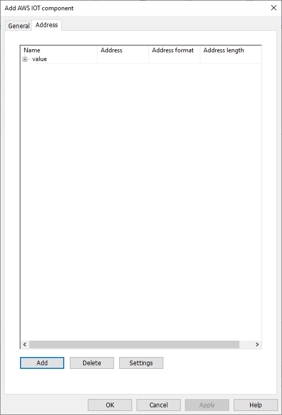
The above figure is an example. If setting like above figure, the subscription side will receive the MQTT message like following format.
{
"object": {
"value": "teststring",
"value (1)": 123,
"value (2)": true,
"value (3)": "",
"value (4)": 0,
"value (5)": true
},
"array": [
10,
20,
30
],
"value (6)": " 2023-04-27T03: 53: 20.156271 "
}
New component: Add a new data component. Components can have multiple data formats; each data format has its own Name and Value. The data of the component is included in braces {}.
New value: Add a value, string, or timestamp. When it is a value or a string, data can be read for a fixed value or from a specified address.
Delete: Delete the selected field.
Settings: Modify the selected field. If the selected fields are components and arrays, only the names can be modified. But components and arrays include values that can modify parameters.
Template: Paste the JSON text, and the system will automatically arrange the schema to conform to this JSON format, saving the time of self-definition.
Preview: Preview JSON data in an easy-to-read format.
✎Note: A Topic can be up to 512 nodes (including payload), and a node name can be configured to be up to 255 characters length.
Security settings
The topic is published only when the register status matches the setting. As shown in the following figure, this topic will not be published until the address HDX0.0 is set to ON.

MQTT topic subscription
Select [Topic subscription] and click [Add] to enter general property settings and address settings. The maximum number of MQTT subscription topics is 255.
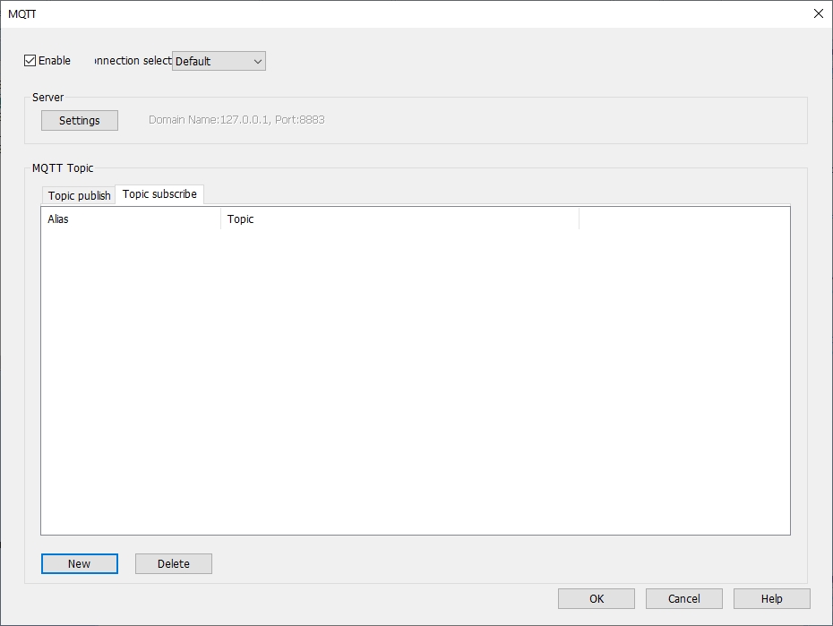
General properties

Alias: Set the project name of the MQTT theme. Maximum input length: 255 characters, cannot be empty.
Topic: Topics subscribed from the MQTT server. Maximum input length: 255 characters, cannot be empty.
Compression type: The transport compression type of a subscription topic must be the same as that of a publication topic.
QoS: MQTT provides three levels of reliability called service quality. The service quality of message transmission determines whether the message is guaranteed to be delivered.
0: Messages are sent only once, and delivery is not guaranteed.
1: Message must be delivered at least once.
2: Message is delivered just once.
Content format:
Raw data: There is no original data in a specific format.
JSON (General): JSON format of single-layer structure.
JSON (Advanced): JSON format of flexibly customizable nested structure.
Verify timestamp: The user can decide whether to verify the timestamp or not. When checked, it indicates that the received data timestamp must be strictly incremented before it can be updated. Otherwise, it will be judged as outdated data and not updated.
Use the top "d" symbol in the message format:
This function is only supported when the content format uses [JSON (General)]. When checked, the message format is as follows:
{
"d": {
"addressName1": ...,
"addressName2":...
},
"ts":...
}
When unchecked, the message format is as follows:
{
"addressName1": ..., "addressName2":...,
"ts":...
}
Please select the appropriate settings according to the data source.
Address setting
①Address settings when content formats use [Raw Data] and [JSON (General)].

Add: Establish the address where the data is placed after the topic is subscribed, and the length of each address can be set separately.
Delete: Delete the address.
Settings: Modify the address and name.

Remove JSON array brackets' ['and'] ':
When using non-array bits or characters, array symbol can manually be removed.
✎Note: A topic can be configured up to 255 nodes. The name length of a node can be configured up to a maximum of 255 characters and cannot be empty.
② Address setting when the content format uses [JSON (Advanced)]. [JSON (Advanced)] supports nested structure, which can use components, arrays and other forms. Timestamps and data names can also be customized, which is a more flexible design method.

New component: Add a new data component. There can be multiple data formats in a component, each with a name and a value. The data of the component is included in braces {}.
New Array: Add a new data array. Arrays can have multiple data formats, but only one name. The data of the component is included in brackets [].
New value: Add a value, string, or timestamp. When it is a value or a string, data can be read for a fixed value or from a specified address.
Delete: Delete the selected field.
Settings: Modify the selected field. If the selected fields are components and arrays, only the names can be modified. But components and arrays include values that can modify parameters.
Template: Paste the JSON text, and the system will automatically arrange the schema to conform to this JSON format, saving the time of self-definition.
Preview: Preview JSON data in an easy-to-read format.
✎Note: A Topic can be up to 512 nodes (including payload), and a node name can be configured to be up to 255 characters length.
Security settings
The topic is published only when the register status matches the setting. As shown in the following figure, this topic will not be published until the address HDX0.0 is set to ON.

MQTT Server Settings (Huawei)
General
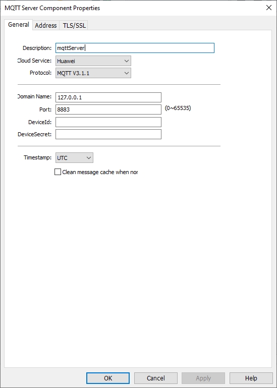
Description: Enter a description or comment about the server. Maximum input length: 255 characters, cannot be empty.
Cloud service description: (Select Huawei)
① Common (Common Platform): General MQTT publish-subscribe topic mode.
② AWS IoT (Amazon): Using "AWS IoT" as the Broker, using Thing to transfer data and support Shadow function.
③ ALi (Alibaba Cloud): Using "Alibaba Cloud" as Broker.
④ Huawei (Huawei Cloud): Using "Huawei Cloud" as Broker.
Communication protocol: MQTTv3.1, v3.1.1 and v5 are supported.
Domain name: Set the domain name of the MQTT server that subscribe message. Maximum input length: 128 characters, cannot be empty, supports letters, numbers, "-", “.”. The symbol cannot be placed at the first character or last character of name.
Port number: Set the MQTT server port to subscribe message. Range: 0~65535, cannot be empty.
DeviceId: Device ID generated when registering the device in Huawei Cloud. Maximum input length: 128 characters
DeviceSecret: Customized password when registering devices on Huawei Cloud Maximum input length: 128 characters.
Timestamp: LOCAL: Using the HMI time as the timestamp. UTC Time: Using UTC+0.
Clean message cache when normal connected: If option is enabled, when the device is disconnected, the message to be published will be cached in the cache area, and then will be published when the device is online again.
Address

Status address: (Total length: 2 words)
HDWn: Display [MQTT] connection status.
| Value | Description |
| 0 | Disable MQTT server connection |
| 1 | Disconnected or connecting |
| 2 | Successfully connected the MQTT server |
HDWn+1: Error prompt
| Value | Description |
| 0 | No error |
| -1 | General error code of wrong operation |
| -3 | Disconnected |
| -4 | Exceed client data concurrency |
| -5 | Invalid UTF-8 string |
| -6 | Null pointer parameter |
| -7 | Topic name is truncated |
| -8 | Wrong protocol structure body |
| -9 | Wrong QOS. (0, 1, 2) is acceptable. |
| -10 | Attempt to use a non-SSL library for SSL connection |
| -11 | Wrong MQTT version |
| -14 | Wrong protocol type |
| -15 | Option is not suitable for the current request version |
| -16 | Call MQTT version that is not applicable to request. |
| -17 | 0 length topic connection |
Buffer usage address: (Total length: 1 word)
Unsuccessful published message will be stored in memory as cache, with a maximum 100,000 messages or 2M. Value display as unit %, and it is carried unconditionally.
HDWn: Display buffer usage.
Control address: (Total length: 194 words)
HDWn: Control the execution or stop of [MQTT Server].
| Value | Description |
| 0 | Ready |
| 1 | Start |
| 2 | Stop |
| 3 | Update |
HDWn+1: Port number of the Huawei Cloud.
HDWn+2: Domain name of the Huawei Cloud.
HDWn+66: DeviceSecret of the Huawei Cloud.
HDWn+130: DeviceSecret of the Huawei Cloud.
TLS/SSL Settings
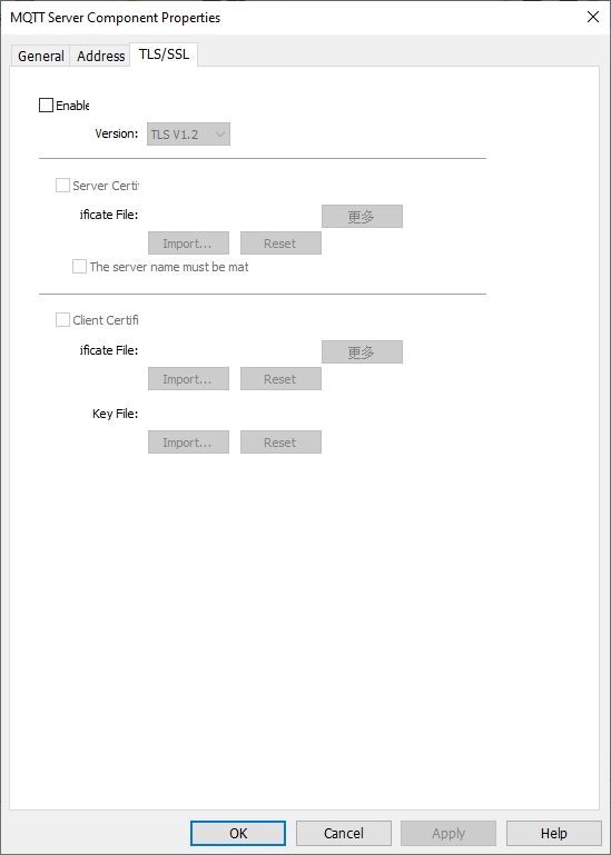
Enable: Enable TLS/SSL encryption. User can manually select encrypted versions of TLS 1.0, TLS 1.1, or TLS 1.2.
Server authentication:
Enable: Verify whether the server certificate has been certified by a Certificate Authority Certificate (CA). Server certificates are sent by the server when connection is established.
Import: Select CA certificate to import.
More: After the import is successful, clicking it will display the certificate details.
Reset: Reset the import information.
The server name must match the certificate information: Verify whether the server name or IP matches with the information in the certificate. Domain name and IP are recorded in the Subject Alternative Name from certificate.
Client authentication: The private key and client certificate are the data required for the server to authenticate the client end.
Certificate:
Import: Select certificate to import.
More: After the import is successful, clicking it will display the certificate details.
Reset: Reset the import information.
Key:
Import: Select the key to import.
More: After the import is successful, clicking it will display key details.
Reset: Reset the import information.
MQTT Topic
MQTT topic publish
Select [Topic publish], click [Add], enter [Add MQTT topic publish object], and set the general settings and address. The maximum number of MQTT published topics is 255.

General properties

Alias: Set the project name of the MQTT theme. Maximum input length: 255 characters, cannot be empty.
Topic: The topic received by the MQTT server when sending message. Maximum input length: 255 characters, cannot be empty.
Sending mode: (AUTO/TRIGGER)
① AUTO value change mode: When any value changes, MQTT message is published.
a. Minimum time interval between messages: The minimum time interval can be set between messages to avoid over-publishing MQTT messages. When the interval of value change is less than the minimum time interval between messages, the message will be put in the cache. The MQTT message will not be published until the minimum interval between messages is met. Range: 0~3600000ms.
b. Periodic mode: Publish MQTT message by the fixed time. Time interval: Set the time interval for periodic publishing, ranging from 1 to 3600s.
② TRIGGER
When the specified bit is triggered, the MQTT message is published. When HDX0.0 changes from OFF to ON, an MQTT message is published, and HDX0.0 is automatically set to OFF after publishing.
Compression type: Message is compressed before it is transmitted. The compressed message needs to be decompressed before the MQTT client reads it. Zlib, Gzip, or Deflate algorithm can be chosen to compress or decompress the message.
QoS: MQTT provides three levels of reliability called service quality. The service quality of message transmission determines whether the message is guaranteed to be delivered.
0: Messages are sent only once, and delivery is not guaranteed.
1: Message must be delivered at least once.
2: Message is delivered just once.
Retain message: When checked, the MQTT server will keep the latest message.
Content format:
Raw data: Data composed of BYTE data.
JSON (General): Put all data in JSON format of member "d".
JSON (Advanced): JSON format of flexibly customizable nested structure.
Include timestamps: This function is only supported when the content format uses [JSON (General)], and whether to include the timestamp can be decided manually.
Use the top "d" symbol in the message format:
This function is only supported when the content format uses [JSON (General)]. When checked, the message format is as follows:
{
"d": {
"addressName1": ...,
"addressName2":...
},
"ts":...
}
When unchecked, the message format is as follows:
{
"addressName1": ...,
"addressName2":...,
"ts":...
}
As shown above, when unchecked, ts and address names are both key at the same level. Therefore, avoid taking the address name as ts.
Address setting
①Address settings when content formats use [Raw Data] and [JSON (General)].

Add: Establish the address source of the topic. The length of each address can be set separately.
Delete: Delete the address.
Settings: Modify the address and name.

Included in all message sent
Check the options: This topic will include this address every time it publishes a message.
Uncheck the options: When the sending mode is value, message is published only when the value of the address changes.
Remove JSON array brackets' ['and'] ':
Check the options: Remove the array symbol name when using non-array bits or characters.
✎Note: A topic can be configured up to 255 nodes. The name length of a node can be configured up to a maximum of 255 characters and cannot be empty.
② Address setting when the content format uses [JSON (Advanced)]. [JSON (Advanced)] supports nested structure, which can use components, arrays and other forms. Timestamps and data names can also be customized, which is a more flexible design method.

The above figure is an example. If setting like above figure, the subscription side will receive the MQTT message like following format.
{
"object": {
"value": "teststring",
"value (1)": 123,
"value (2)": true,
"value (3)": "",
"value (4)": 0,
"value (5)": true
},
"array": [
10,
20,
30
],
"value (6)": " 2023-04-27T03: 53: 20.156271 "
}
New component: Add a new data component. Components can have multiple data formats; each data format has its own Name and Value. The data of the component is included in braces {}.
New value: Add a value, string, or timestamp. When it is a value or a string, data can be read for a fixed value or from a specified address.
Delete: Delete the selected field.
Settings: Modify the selected field. If the selected fields are components and arrays, only the names can be modified. But components and arrays include values that can modify parameters.
Template: Paste the JSON text, and the system will automatically arrange the schema to conform to this JSON format, saving the time of self-definition.
Preview: Preview JSON data in an easy-to-read format.
✎Note: A Topic can be up to 512 nodes (including payload), and a node name can be configured to be up to 255 characters length.
Security settings
The topic is published only when the register status matches the setting. As shown in the following figure, this topic will not be published until the address HDX0.0 is set to ON.

MQTT topic subscription
Select [Topic subscription] and click [Add] to enter general property settings and address settings. The maximum number of MQTT subscription topics is 255.

General properties

Alias: Set the project name of the MQTT theme. Maximum input length: 255 characters, cannot be empty.
Topic: Topics subscribed from the MQTT server. Maximum input length: 255 characters, cannot be empty.
Compression type: The transport compression type of a subscription topic must be the same as that of a publication topic.
QoS: MQTT provides three levels of reliability called service quality. The service quality of message transmission determines whether the message is guaranteed to be delivered.
0: Messages are sent only once, and delivery is not guaranteed.
1: Message must be delivered at least once.
2: Message is delivered just once.
Content format:
Raw data: There is no original data in a specific format.
JSON (General): JSON format of single-layer structure.
JSON (Advanced): JSON format of flexibly customizable nested structure.
Verify timestamp: The user can decide whether to verify the timestamp or not. When checked, it indicates that the received data timestamp must be strictly incremented before it can be updated. Otherwise, it will be judged as outdated data and not updated.
Use the top "d" symbol in the message format:
This function is only supported when the content format uses [JSON (General)]. When checked, the message format is as follows:
{
"d": {
"addressName1": ...,
"addressName2":...
},
"ts":...
}
When unchecked, the message format is as follows:
{
"addressName1": ..., "addressName2":...,
"ts":...
}
Please select the appropriate settings according to the data source.
Address setting
①Address settings when content formats use [Raw Data] and [JSON (General)].

Add: Establish the address where the data is placed after the topic is subscribed. The length of each address can be set separately.
Delete: Delete the address.
Settings: Modify the address and name.

Remove JSON array brackets' ['and'] ':
When using non-array bits or characters, array symbol can manually be removed.
✎Note: A topic can be configured up to 255 nodes. The name length of a node can be configured up to a maximum of 255 characters and cannot be empty.
② Address setting when the content format uses [JSON (Advanced)]. [JSON (Advanced)] supports nested structure, which can use components, arrays and other forms. Timestamps and data names can also be customized, which is a more flexible design method.
New component: Add a new data component. There can be multiple data formats in a component, each with a name and a value. The data of the component is included in braces {}.
New Array: Add a new data array. Arrays can have multiple data formats, but only one name. The data of the component is included in brackets [].
New value: Add a value, string, or timestamp. When it is a value or a string, data can be read for a fixed value or from a specified address.
Delete: Delete the selected field.
Settings: Modify the selected field. If the selected fields are components and arrays, only the names can be modified. But components and arrays include values that can modify parameters.
Template: Paste the JSON text, and the system will automatically arrange the schema to conform to this JSON format, saving the time of self-definition.
Preview: Preview JSON data in an easy-to-read format.
✎Note: A Topic can be up to 512 nodes (including payload), and a node name can be configured to be up to 255 characters length.
Security settings
The topic is published only when the register status matches the setting. As shown in the following figure, this topic will not be published until the address HDX0.0 is set to ON.

OPCUA Server
1.Open the OPCUA server tool
[Project]→[OPCUA server]→[Enable]

2.Set General properties

Description:Description of OPCUA server, character length 0~255.
OPC TCP:Set URL of OPCUA server.
Port number:The port used by the client for communication.Default: 4840.
Server name:Set the name of Server,character length 0~255.
Security:OPCUA server provides four security policies and three authentication methods, and different encryption methods can be implemented through different combinations.
3.User authentication

Anonymous:When the client chooses to log in anonymously, the permissions to interact with the server include brows, read and write.
User name password:The user name and password here are equivalent to the user name and password set on the [Project Settiing\User Login] page. When the client logs in to the server by using the user name and password, the user password used has the same group level as that configured by the server and has corresponding permissions.
4.Main interface

Enable:Check to configure the relevant properties of the OPC UA server
Server\Settings:Configure OPC UA Server Properties
List of tags:Display the defined tags
New group:Add a new group to manage tags
New label:Add the address label you want to monitor, and the name cannot be empty. The length of the label name ranges from 1 to 255.
Settings:When a label is selected, click to jump to the label configuration interface.
When a group is selected, click to configure the group name.
Cancel:Able to delete tags or groups
5.Label configuration

Name:Tag name
Type:Indicate the read and write attributes of the label. The read attributes are checked by default
Address:Configure the address to be monitored by the label
Data Type:Represent the data type of this label
Array length:When the set length exceeds 1, it means that the label is an array, and the array range is 1 to 255.