07 Tools
Compile Project
This chapter provides information about the compiling project and a description of how to using compiling function and modify errors according to compiling outputs. Compiling project is the one of most important steps, it checks project, saves all settings and then creates project file.
Procedure
Users could use "PIStudio" to execute compiling, and check results in output windows. The follow procedure shows how compile a project.
Users need to check the result, and modify errors. Project file is only created when compiling is successful.
Steps
- Finish project programming.
- Click "Compile" button.

- Check the compiling windows in below of software interface.
- Check the information of error (in red).
- Compile project again after modification.
- Until get successful information of compilation.
Result
After compilation, PIStudio creates .wmt file for download.
Decompile
When uploading a project from the HMI to the PC, the "**.wmt" file is obtained, which needs to be decompiled before it could be opened with the PIStudio software.
This section introduces this tool in detailed.
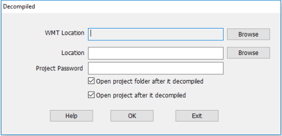
Steps
- Open "Decompiledv tool”.
- Select WMT file by clicking "Browse" in "WMT location".
- Set save path in "Location".
- Enter password in "Project Password" (Enter as needed).
- Click "OK" to perform the operation.
Result
A project folder is created.
Simulation
The following steps will show how to use simulator in PIStudio.
Offline simulation
- Click "off-line" to open the simulation window.
- Check HMI screen in window.
Online simulation
- Click "on-line" to open "online simulation serial select tool" .
- Select COM port in PC for link.
- Click "OK" to open simulation window.
- Check HMI project in window.
Off-line
It provides function to users for checking the HMI project display on PC.
Requirement
Project is compiled and .wmt file exists
Steps
- Click [Off-line] button;
- Check project display and some non-communication functions in Off-line simulator;
On-line
It provides function to users for checking the HMI project and communication.
Requirement
- Project is compiled and .wmt file exists;
- PC is connecting with PLC device;
Steps
- Click [On-line] icon to open the online simulator
- The [Online Emulator Serial Select Tool] pop-up automatically, as following picture shows, the detailed description showed in following content.

- PC link1/ PC link2/ PC link 3 correspond to HMI protocol list number;
- COM ports in the drop-list correspond to PC port.
- If online is for testing ethernet protocol, there is no need to select.
Result
- On-line simulator runs HMI project;
- HMI project is communicating with PLC device;
Download project
This chapter provides information about the download project and a description of how to download project to HMI.
Project Upload/Download
Not opening the project file directly, while open the download tool from PIStudio shortcut menu from Start menu to upload, download project or firmware.
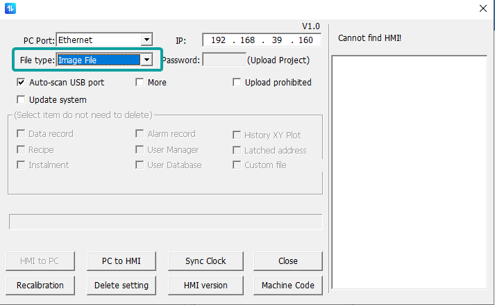
Firmware Download
If want to download the firmware file or logo file, please change the File type to Image File
Steps
- Connect HMI via USB programming cable (D type USB cable).
- Find the download tool from shortcut menu.
- Download or upload the file according to need.
UDisk Download Tool

Udisk Download
Introduction
"USB flash disk download tool" could create project and firmware updating file. This section introduces how to use this tool.
Generate the U disk file (Project file, firmware file, current version firmwares), then insert the UDisk into HMI, enter the HMI background interface(long press the upper right corner) to process the update operations.
Steps
- Open the PIStudio.
- Click on
 from toolbar.
 - Select the file type want to update with.
- Finish the generation into Udisk.
- Insert Udisk into HMI.
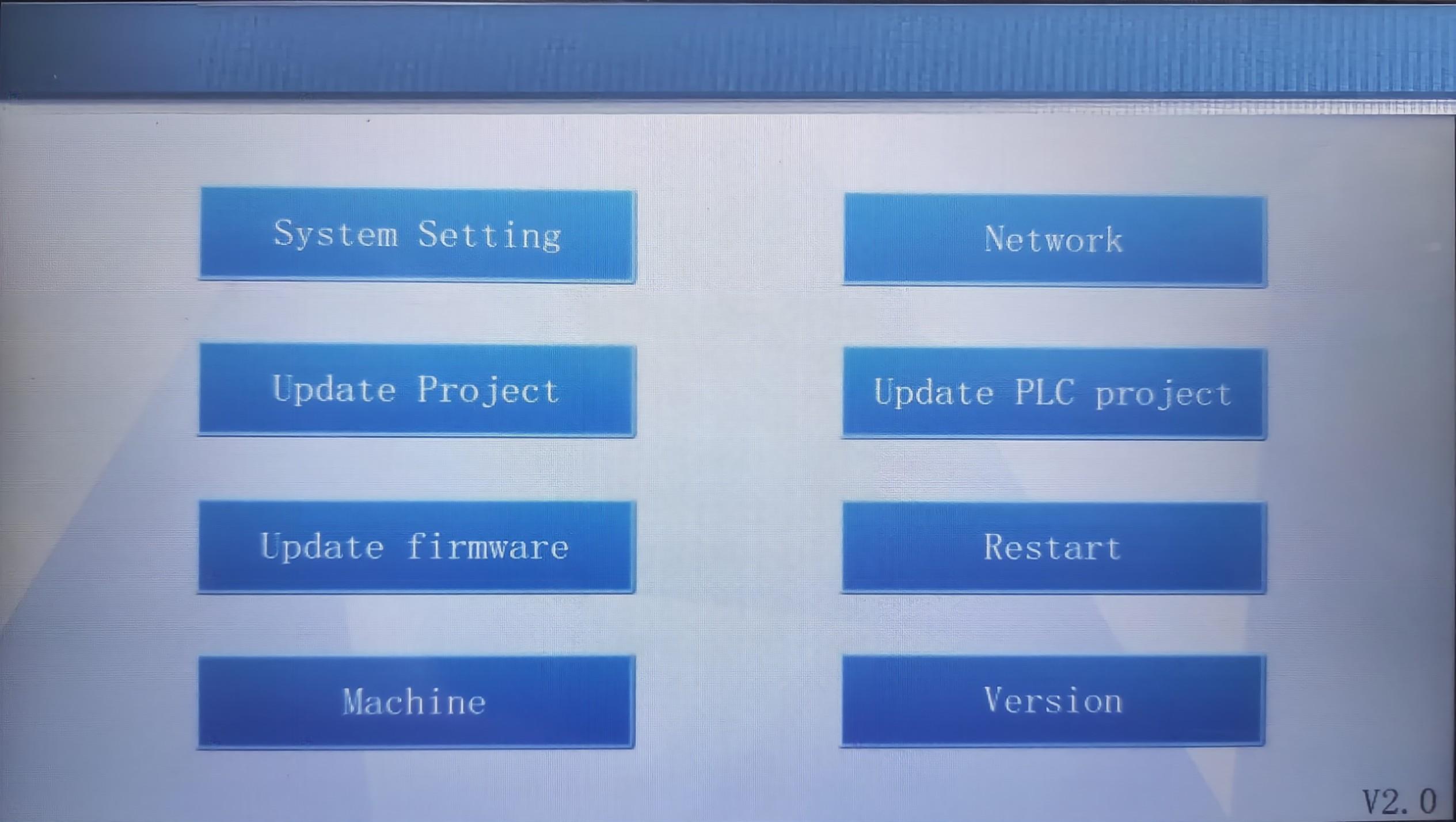
- Long press the HMI upper right corner for lasting over 5 seconds, it will enter the background setup.
- Update the file from Update tab.
The difference between HMI V1.0 and HMI V2.0: Long press the upper right corner of HMI for over 5 seconds to enter the HMI background to view HMI version information.
- If it is HMI V1.0, when you create project, you should select the interface of HMI V1.0.
- If it is HMI V2.0, when you create project, you should select the interface of HMI V2.0.

Update project
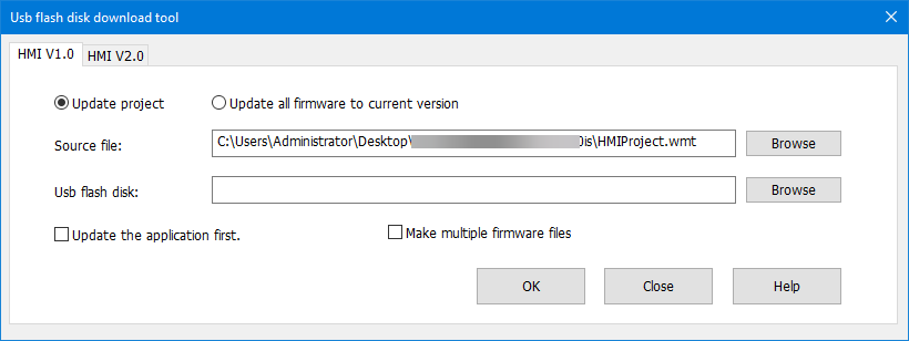
Create single project (HMI V1.0)
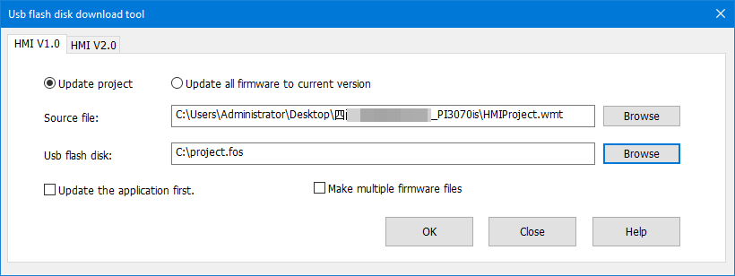
Steps
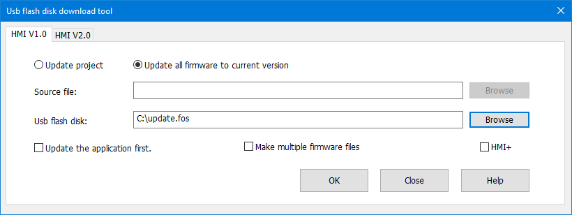
- Click "Udisk download" to open tool window in HMI V1.0.
- Select "Update project" option.
- Set project in "source file". The file format is ".wmt".
- Set USB flash disk path. The default file is "project.fos" and cannot be changed.
- Select "Update the application first" according to requirements, this option means if USB flash disk contains project and firmware updating files at the same time, it will update project firstly.
- Click [OK] to execute the operation.
- Copy the project file "project.fos" to Udisk, and insert the Udisk to HMI to download the project.
Create multiple projects (HMI V1.0)

Steps
- Click "Udisk download" to open tool window in HMI V1.0.
- Select "Update project" and "make multiple firmware files".
- Set project in "source file". The file format is ".wmt".
- Set USB flash disk path and create project "XX.wpj".
- Select "Update the application first" according to requirements, this option means if USB flash disk contains project and firmware updating files at the same time, it will update project firstly.
- Click [OK] to execute the operation.
- Copy the project file "XX.wpj" to Udisk, and insert the Udisk to HMI to download the project.
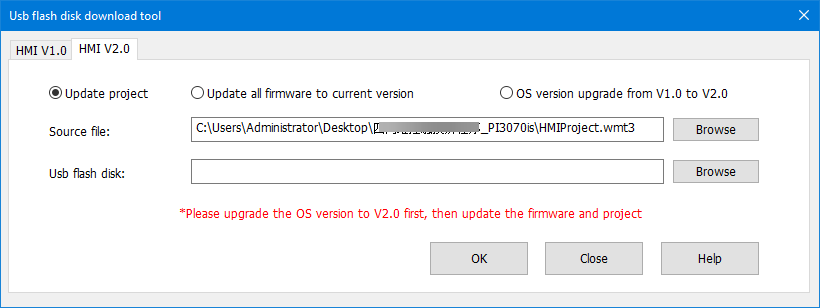
Create projects (HMI V2.0)

Steps
- Click "Udisk download" to open tool window in HMI V2.0.
- Select "Update project".
- Set project in "source file". The file format is ".wmt3".
- Set USB flash disk path. The default file is "XX.wmt3".
- Select "Update the application first" according to requirements, this option means if USB flash disk contains project and firmware updating files at the same time, it will update project firstly.
- Click [OK] to execute the operation. It will pop-up below window.
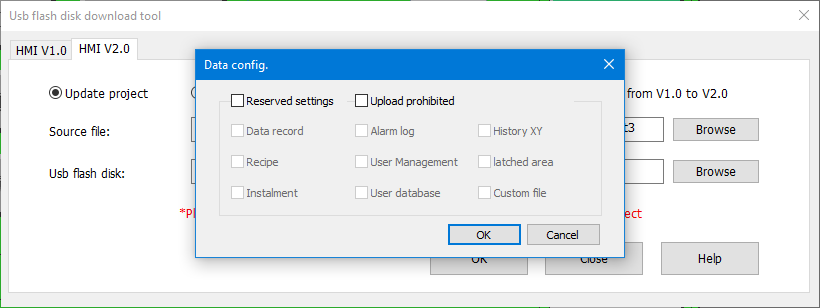
- Copy the project file "project.fos" to Udisk, and insert the Udisk to HMI to download the project.
Update firmware
Create one firmware file (HMI V1.0)
Steps
- Click "Udisk download" to open tool window in HMI V1.0.
- Select "Update all firmware to current version".
- Set USB flash disk path. The default file is "update.fos".
- Click [OK] to execute the operation.
- Copy the project file "update.fos" to Udisk, and insert the Udisk to HMI to update system version.
Create multiple firmware files (HMI V1.0)
Steps
- Click "Udisk download" to open tool window in HMI V1.0.
- Select "Update all firmware to current version" and "make multiple firmware files".
- Set USB flash disk path and create project "XX.wos".
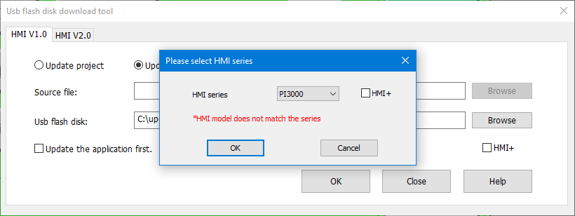
- Click "OK" to execute the operation and pop-up a screen to select the corresponding HMI series.
- Copy the project file "XX.wos" to Udisk, and insert the Udisk to HMI to update system version.
Create firmware file (HMI V2.0)

Steps
- Click "Udisk download" to open tool window in HMI V2.0.
- Select ""Update all firmware to current version".
- Set USB flash disk path. The default file is "XX.osf3".
- Click "OK" to execute the operation and pop-up a screen to select the corresponding HMI series.
- Copy the project file "XX.osf3" to Udisk, and insert the Udisk to HMI to update system version.
HMI Settings
please click "HMI Setting" for the details.
Udisk Download PLC program
HMI background
ig series HMI background

Procedure of downloading PLC program
- Use PLC programming software to make a U disk PLC program file "update.bin".
- Store the file on a Udisk /SD card.
- When the HMI and PLC are communicating normally, insert the U disk or SD card into the HMI interface and switch the DIP switch of PLC to "stop".
- Long press the upper right corner of HMI to enter the background.
- When the HMI display "Updated, please restart HMI.", PLC program download is complete.
Prompt messages are as follows.
- Prompt: Failed to open COM!
- Prompt: Failed to read file!
- Prompt: The PLC Version is mismatch!
- Prompt: The download password is error!
- Prompt: The download Program ID is error!
- Prompt: The PLC has download Program ID,download error!
- Prompt: Download timeout,please check your connection and retry again!
- Prompt: Update PLC subProgram is failed!
- Prompt: PLC is not supported UnUpload!
- Prompt: PLC is not supported subProgram!
- Prompt: PLC is not supported ProgramID!
- Prompt: Update PLC Program is failed!
- Prompt: Update PLC Program is Successful!
Password tool
The password tool is used for setting the password for dynamic installment payments.
Dynamic installment function creates a "dynamic password" by the "key" and "expiration". In the same project, the dynamic installment and static installment are mutually exclusive.
This section will introduce how to use this tool.
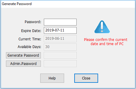
Description
- Password: It is for entering password, which set in "Project Settings". Each project has a unique password. Enter the key and set expire time to generate a new password.
- Expire Date: It is for setting expire date for installment.
- Current Time: Just display current date, read only.
- Available Days: Display the current time and the interval between expire time and current time.
- Generate Password: Click it to generate the password according to the password and expire time. This password is used for setting expire time.
- Admin Password: It is available for every payment; this password will end all payments. A password will generate a corresponding unique Admin password. Once you enter the correct Admin password, the installment function would be closed and won't pop-up again.
Address List
[Address list] could display all addresses which are used in project, this section will introduce this tool in detailed.
Description
- Connection: Select HMI connection, such as COM2 Modbus RTU;
- Address mode: Select word address or bit address;
- Address type: Select register, or function code, such as 4;
- Station: Select connected device station;
- Start address: Set start address in window;
- Window: Display all addresses start from [Start address], red means occupied, green means unoccupied, as below figure shows;

- Information: It is display the selected address information in project, as below figure shows;
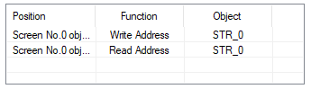
- Replace: Enter new address to replace the selected address in project;

Download Tool
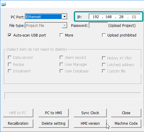
The download tool is mainly used for project transfer, and also comes with other functions, such as synchronization time, checking firmware version, and so on.
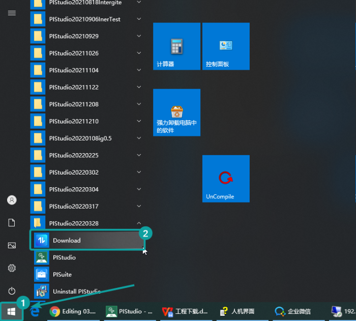
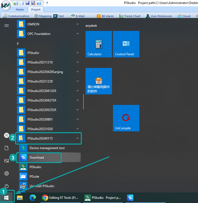
Where to enter
The download tool is on the shortcut menu. Click the Start>PIstudio>Download
HMI to PC option(Upload direction) is disabled when open the download tool inside the PIStudio.

Suggest the user open the download tool from the Start menu if want to upload project or download image files.
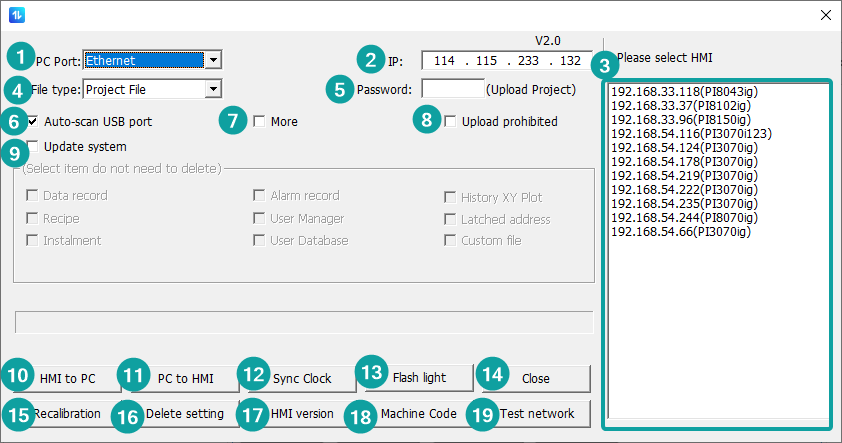
Description
| No. | Function | Description |
|---|---|---|
| 1 | PC Port | Connection method between PC and device, there are mainly USB port and Ethernet port; |
| 2 | IP | IP address for download (Only valid when Ethernet download); |
| 3 | Search result list | When Ethernet download is selected,the tool would automatically detect all the devices on the same LAN*① |
| 4 | File type | Select the file type : HMI V1.0: project (.wmt) or image file (.osf2); HMI V2.0: project file (.wmt3) or image file (.osf3); |
| 5 | Password | Only valid when upload the project (HMI to PC option). It is using the [Designer Password] from Project Settings |
| 6 | Auto-scan USB port | USB download is priority by default; |
| 7 | More | When it is checked, the following checked options will be reserved. Otherwise, all the files and configuration settings would be deleted when cover the new project; |
| 8 | Upload prohibited | Check it to indicate that the project will not be uploaded to the computer(HMI to PC option); |
| 9 | Update system | Upgrade the HMI system from V1.0 to V2.0; |
| 10 | HMI to PC | Upload the project file from device to PC |
| 11 | PC to HMI | Download the file from PC to device |
| 12 | Sync clock | Synchronize the current PC time to device; |
| 13 | Flash light | Device flash detection to identify the current connected which device it is*② |
| 14 | Close | Close the window |
| 15 | Recalibration | Delete exists calibration file and enter calibration screen |
| 16 | Delete settings | Delete exists configuration files*③ |
| 17 | HMI version | Detect and pop-up current HMI version |
| 18 | Machine code | Get device machine code(for bind into Cloud platform), and it will automatically paste into the clipboard; |
| 19 | Test network | Test the network status of device*④ |
Operation Procedure of Download by USB
- Complete project programming and compile the project;
- Connect HMI via USB programming cable;
- Click the
 in toolbar;
 - Check the [PC Port] drop-list menu, if it shows [USB: Download], it means HMI is accessed by PC via USB download cable. Or select serial port;
- Click [PC to HMI] button to execute project download;
Operation Procedure of Download by Ethernet
Complete project programming and compile the project;
Set HMI IP
- Holding Press upper-right corner of screen into backstage screen as below shows;
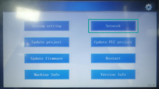
- Click [ Network]into setting screen as below shows;

- Connect HMI via Ethernet cable;
- Click the in toolbar;
- Check the [PC Port] drop-list menu, please select [Ethernet], and enter HMI IP address, as below shows;
- Click [PC to HMI] button to execute project download;
Operation Procedure of Upload by USB
Many users need to upload the project from HMI to PC.
- Open the Download.exe directly, as below shows.

- Connect the HMI to PC via USB programming cable;
- If HMI is accessed, it will show [USB: Download] in [Download] menu;
- Click [HMI to PC] button to execute project upload;
- The .wmt file will be upload to PC;
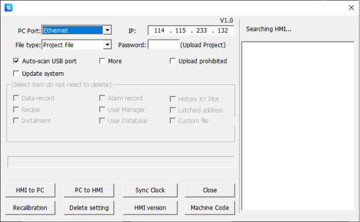
Operation procedure of upload by Ethernet
- Open the Download.exe directly;
- Connect the HMI to PC via Ethernet cable;
- Check the [PC Port] drop-list menu, please select [Ethernet], and enter HMI IP address;
- Click [HMI to PC] button to execute project upload;
- The .wmt file will be upload to PC;
Data Record Upload (Only ig series)
![]()
Data record upload tool could monitor the status of the device in real time, update and export the configuration (Data Record, Alarm Record, Operation record, Recipe) simultaneously, and the user can add, modify, delete, and clear the device configuration.
Real-time Update: After adding HMI, it is checked the Real-time update by default, get the data from the HMI per 15s, save it under the folder "data" of the installation path, and update the synchronization time and real-time update status.
✎Note:
- When modifying, deleting the device, and clearing the list, make sure that the "Real-time Update" is not checked, otherwise an error will be prompted.
- Enter from the start menu of windows, find the installed shortcut of PIStudio:

- Click
 to pop up the PIRecordUpdate, as shown in the figure below.
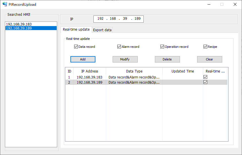
- Searched IP: Display the IP address of the same network segment of online HMI.
- IP: Display the IP address you selected. You may also enter IP address.
If user permission for data upload is configured on the screen, the user name and password are required to unlock the configured user permission when the data upload tool synchronizes or exports data in real time.
Device monitoring: Display the current device's IP address, data type, Real-time update status and other information.
The real-time update status is divided into the following states:
- Normal: PC can detect the HMI and check the real-time update option.
- Abnormal: PC cannot detect the HMI and check the real-time update option.
- No communication: unchecked the real-time update option.
Export data: check the data option you want to export from a certain IP address.
- The data record file is: DataLogFile.db
- The alarm record file is: AlarmFile.db
- The operation record file is: UserMgrFile.db
- The recipe folder is: RecipeFile
✎Note: If the project is configured with multiple groups of data record options, it will be saved in DataLogFile.db, and the table name is "Tb_" + group name.