

This chapter will introduce some of the other things of the PI series HMI.
Regular series settings
Setup menu is used for settings HMI system when HMI is running. Such as communication parameters, real time clock, and other functions.
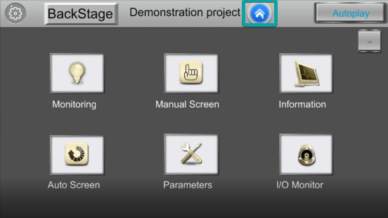
The setup menu interface of V2.0 (in the bottom right corner) version is shown in the below.
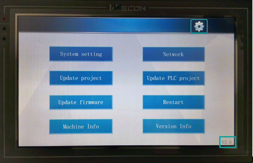
Press the upper right corner to set the displayed language. The default display language of the backend system will be associated with the display language type of the software during project editing.
- If the software is displayed in Chinese, then the system default language is simplified Chinese and could be switch to English.
- If the software is displayed in another language , then the system default language is English and couldn't be switch to English.
Update project/firmware
Those functions are used for update HMI project or firmware via USB flash disk.
Operating procedures
- Generate the project file (firmware) in the u disk first.
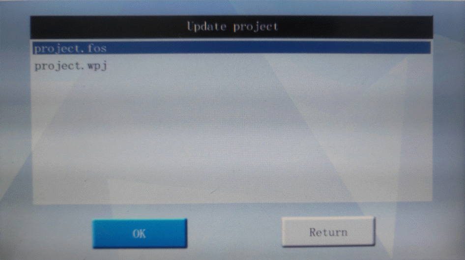
- Select "Update project" as the figure above, and pop-up a screen as the figure below. It displays all the projects in the Udisk. (file with the suffixes ".fos" and ".wpj"). The files with the suffix of "fos" is created by old software, and the file with the suffix of "wpj" is supported by V2.0 (user-defined file names are supported).
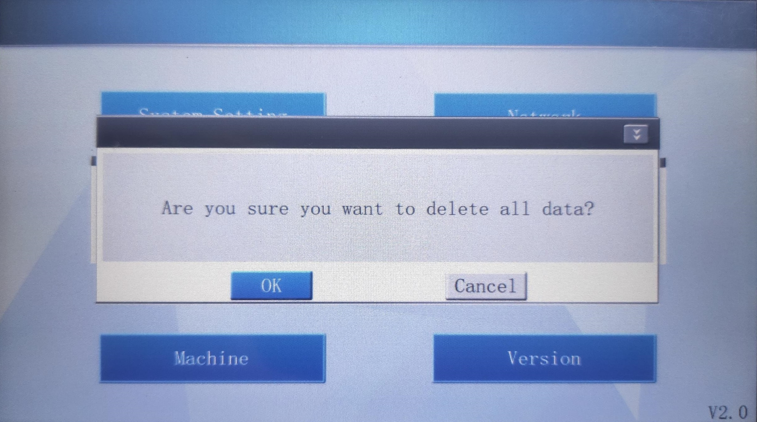
- After selecting a project file, the following interface will pop up: Select whether to retain the parameters of the original project in the HMI when downloading the new project (by default, all will be deleted).
- User could select according to the "Extensions" on the upper right corner of the option box (as shown in the figure below), and retain some configuration files of the original project (please choose carefully as needed to avoid error in application).
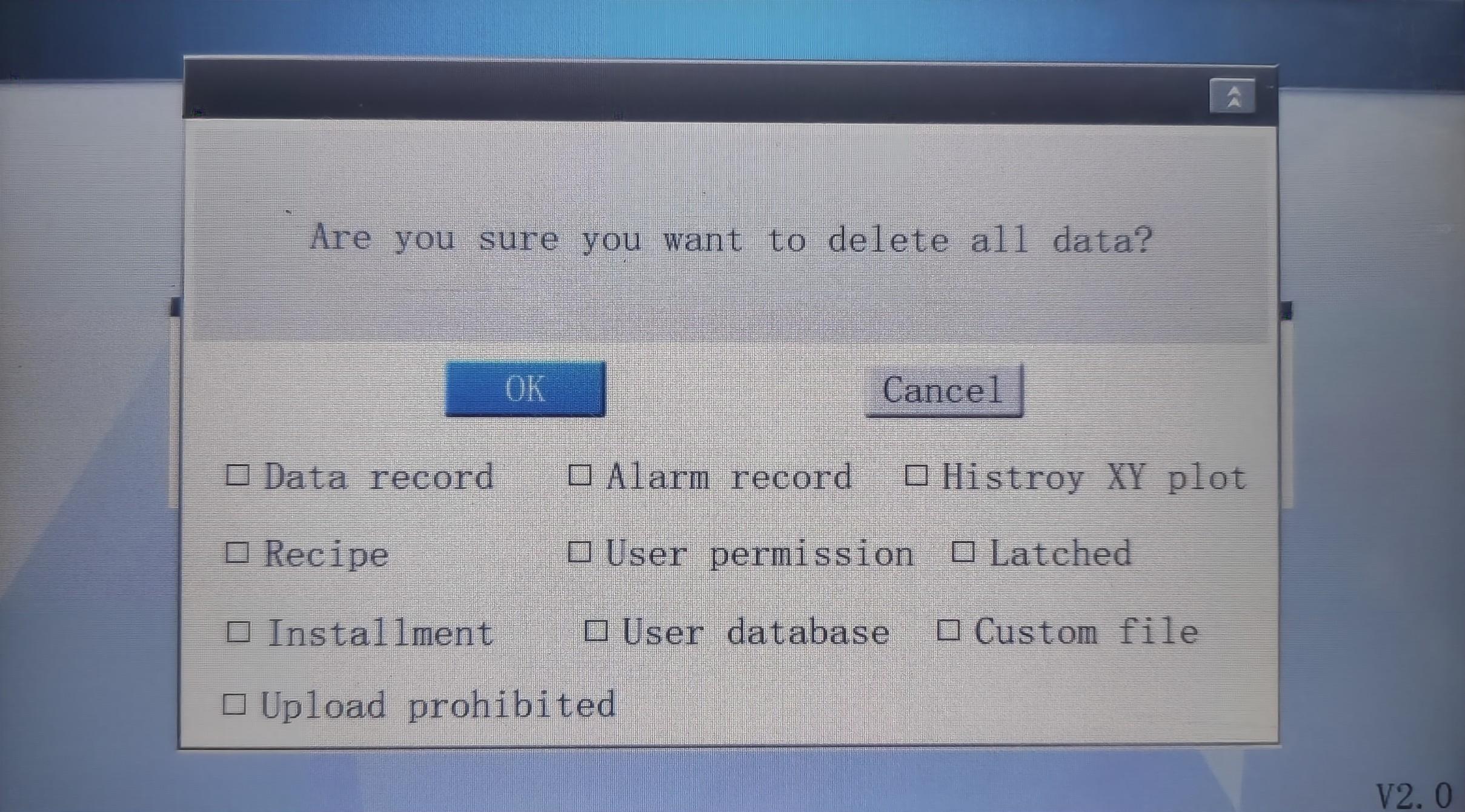
- Click "OKClick "" to delete unchecked item. Click Cancel to retain all data.
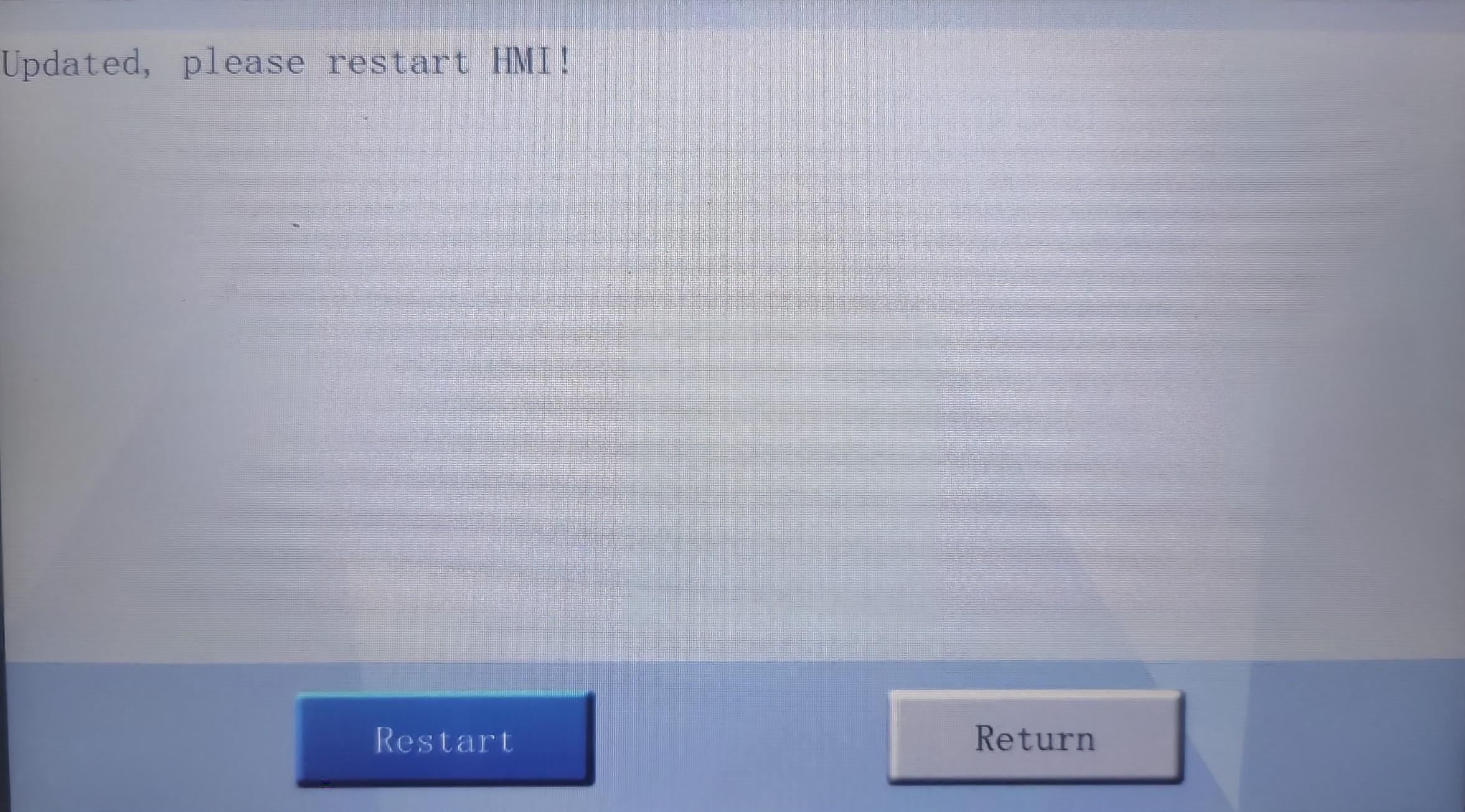
- After downloading project successfully, the following prompt will appear.
Configure network
The network is used for setting and checking the network state of the HMI. All PI series HMI support Ethernet and WIFI (WIFI requires specified USB WIFI device). Click "network" in menu screen to access network configuration interface as below.

WIFI
1. Enable the "WIFI" function, the HMI will search for WIFI signals as shown below.
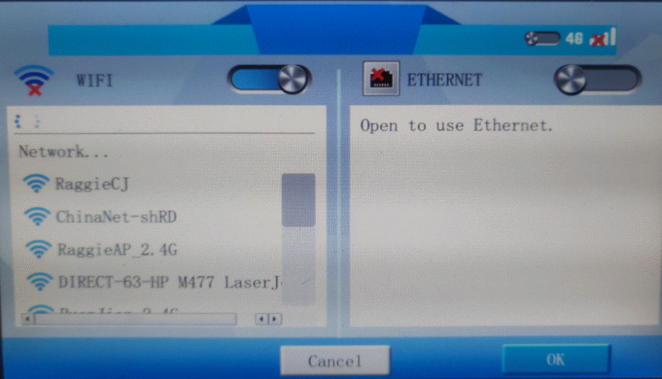
2. Select a WIFI, it will pop up a keyboard to input password.

3. After inputting correct password, HMI will get a dynamic IP.

Ethernet
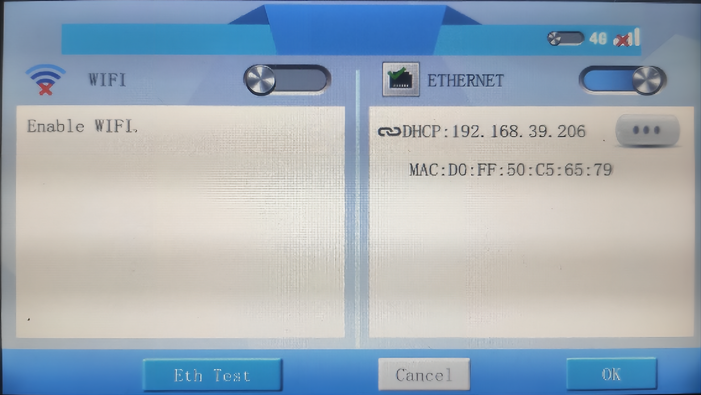
1. Enable the "Ethernet" function. If the network connection is normal, the IP address and MAC address of the HMI will be displayed, as shown in the following figure.
 2. Click "Eth Test" to pop up test window as shown below.
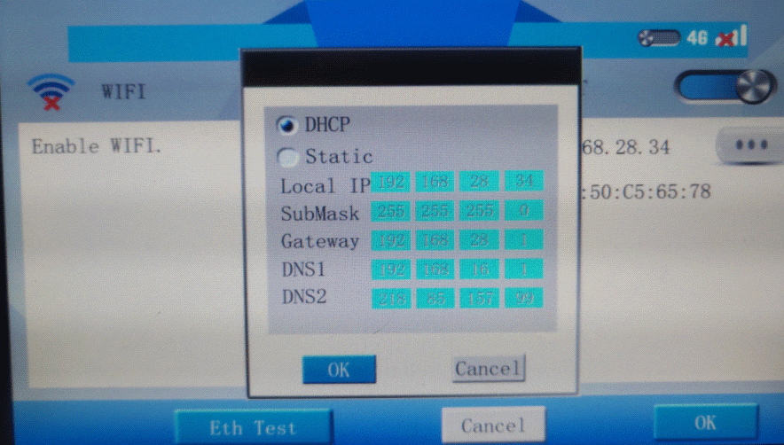
 3. Click
  to select DHCP or Static IP as below.
ig series settings
Long press the upper right corner of HMI, the system setting interface of ig HMI would be displayed as below.

- HMI information
- Model: the model of HMI
- Serial NO. : the serial number of HMI
- Machine ID: the machine code of HMI. The first 20 digits are the serial number.
- HMI: Display the version information of the HMI
- The icons in the lower right corner are USB-A device, 4G network, Ethernet network, WIFI network and cloud access network status respectively. Green indicates that the device/network is available. Black indicates that the device/network is unavailable.
 | USB-A device is not connected |  | USB-A device is connected |
 | 4G network is disconnected. |  | 4G network is connected. |
 | Ethernet is disconnected. |  | Ethernet is connected. |
 | WLAN network is disconnected. |  | WLAN network is connected. |
 | The current network status cannot be uploaded to the cloud. |  | The current network status can be uploaded to the cloud. |
Ethernet
If the Ethernet function is enabled and the network connection is normal, the IP address and MAC address of the HMI are displayed, as shown in the following figure.
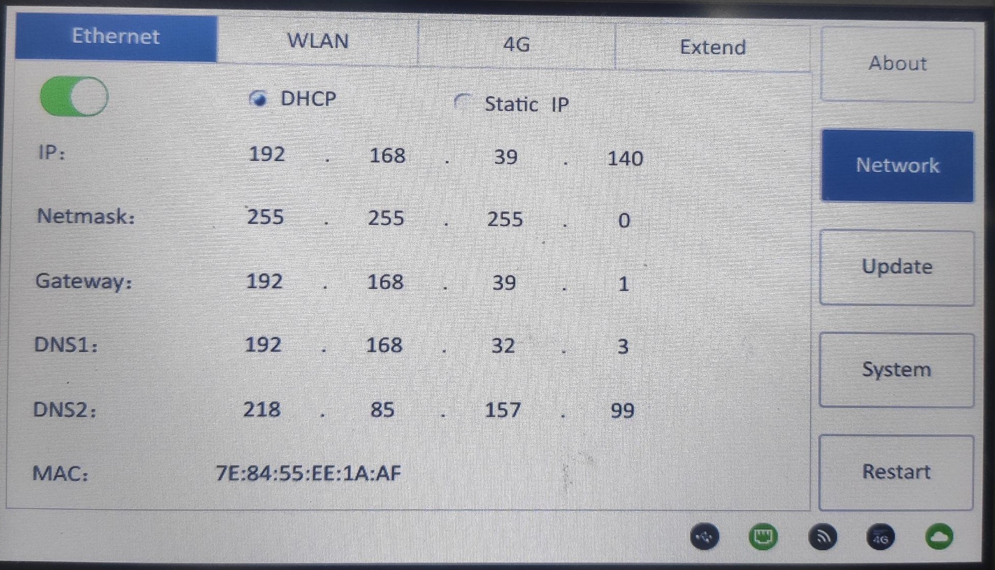
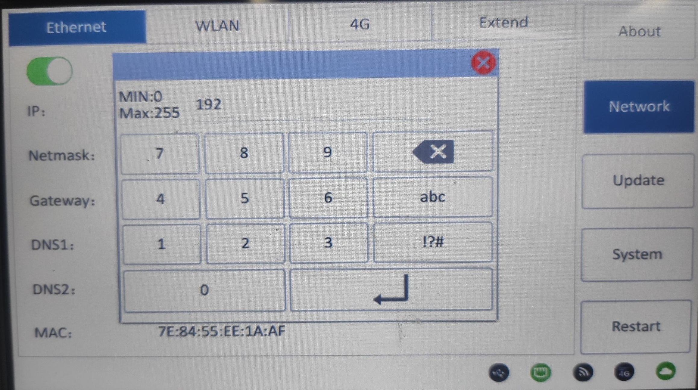
static IP: Click the corresponding horizontal line to change the IP address, as shown in the following figure.
System

General
General settings of the system include: data/time, time zone, backlight time, brightness, beep, beep time, beep tone.
- Data/time: Display the current system time. Click the horizontal line can change it directly, and click save after modifying, otherwise the modification is invalid.
- Time zone: The legal area of common time standard, default "China/beijing".
- Backlight time: Set the rest time after the HMI is not operated for a long time, the maximum is 3600 seconds.
- Brightness: set the brightness of HMI.
- Beep: Activate and deactivate the beep.
- Beep time: 0 to1000ms. The beep time length can be adjusted.
- Beep tone: Adjust the beep sound, and five types are provided.
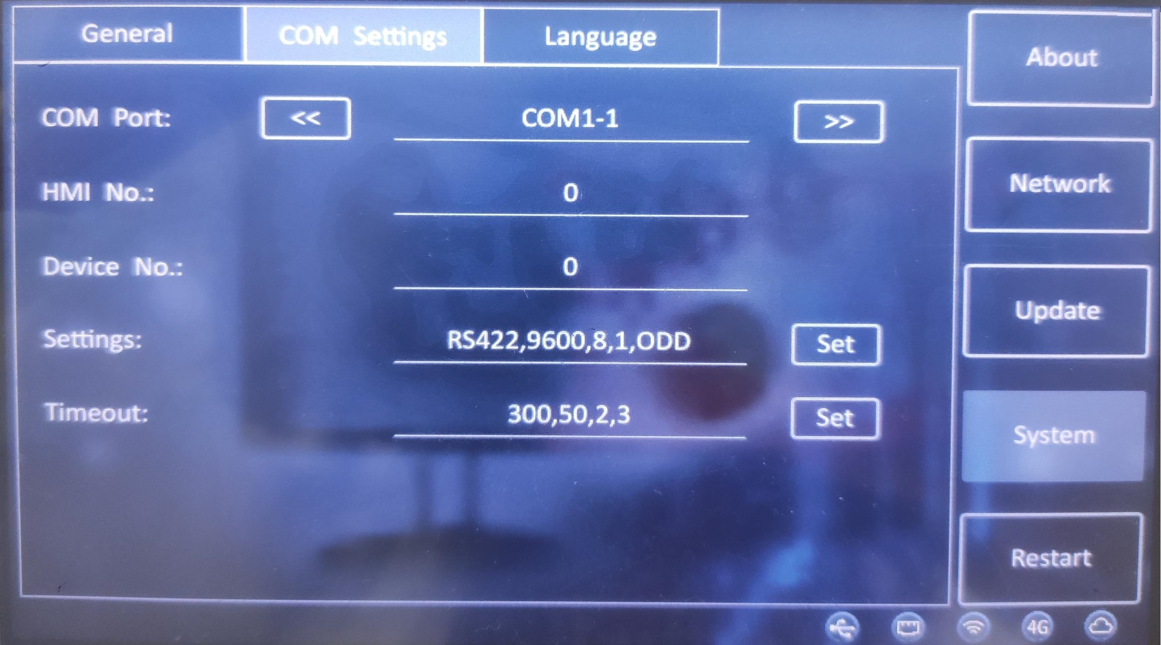
COM settings
COM settings include serial port number, HMI station number, device station number, serial port parameters, and timeout period. As shown in the picture below:
Do not change the settings at will. After modification, the device may fail to communicate.
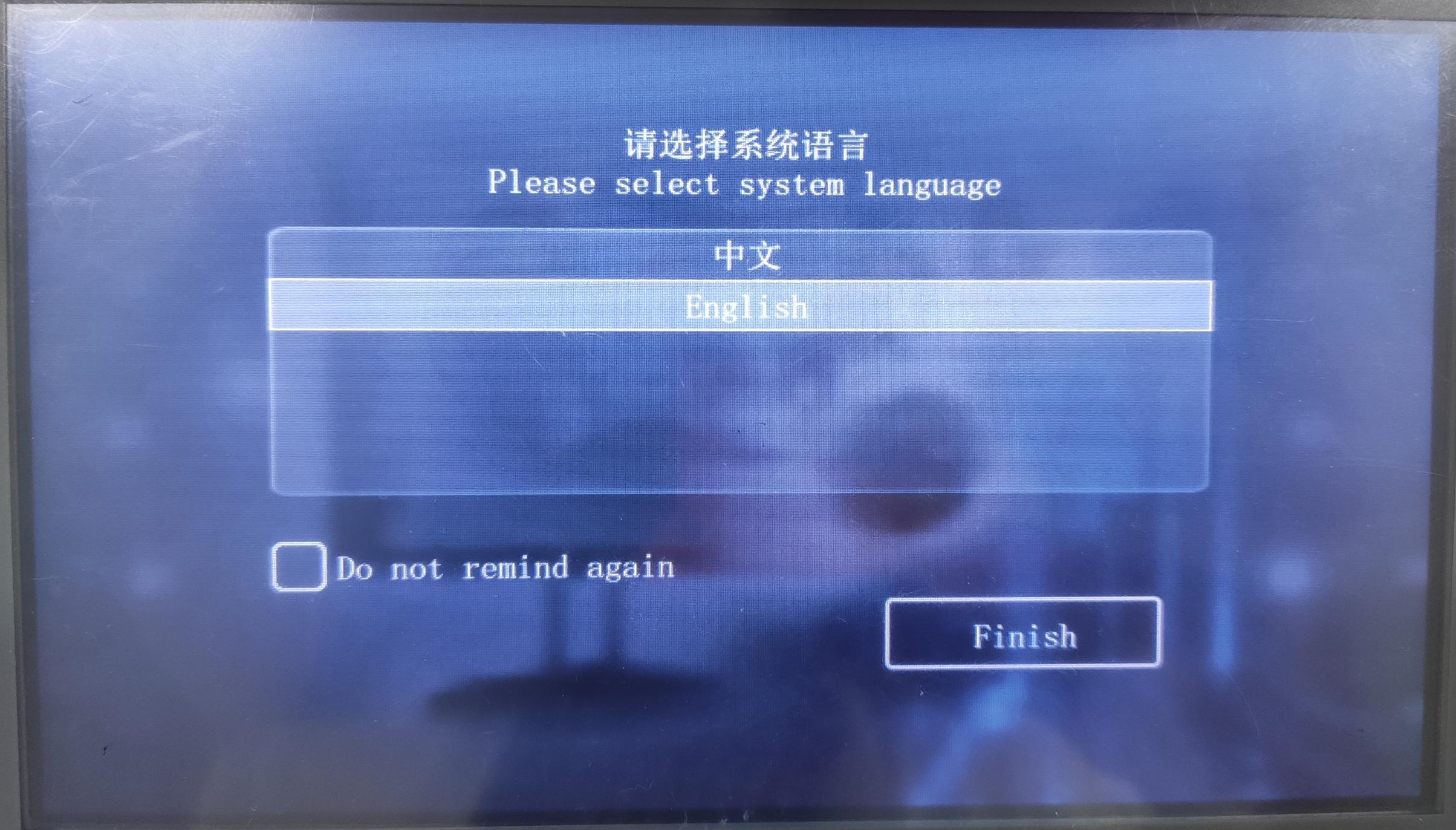
Language
- If the software display language is Chinese, the default language of the system is simplified Chinese. You can switch it to English in settings (as shown in the following figure);
- If the software is displayed in other languages, the system will display English by default, and cannot switch to English in the setting.
Update PLC project
This function is for update WECON PLC project via USB flash disk when HMI is communicating with PLC
Operating procedures:
- Place update file into root directory of USB flash disk.(Default file name is update.bin, customizable)
- Switch DIP (PLC) to stopped state.
- Insert USB Flash disk into HMI.
- Into HMI setup menu.
- Select update PLC project.
- When the HMI screen prompts "Download Successfully!", the PLC project download is complete.
Video tutorial:
✎Note:
- This function is available in PI series HMI.
- If project contains sub-program, the update time will be longer.
Recalibration
When the contact of the screen drifts or the coordinates of the HMI interface are shifted, the operation of the HMI will be inaccurate. In order to recalibrate the contact coordinates of the HMI interface, the calibration file in the HMI needs to be deleted and recalibrated.
There are two methods for recalibration.
Method 1
- Connect HMI to PC via programming port (USB-B).
- Power ON HMI, and open download tool as below.
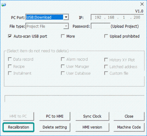
- Please make sure HMI is detected by software.
- Click [Recalibration], and restart HMI.
- After HMI rebooting, it displays pictureas below.
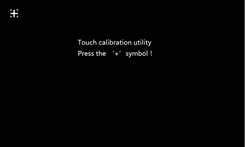
- Long press the center of '+', after success, it will automatically jump to the next '+', after calibrating the '+' point on the interface (a total of 5 '+' points), the HMI will prompt success, and re-load the project screen . (It is recommended to use a professional calibration pen);
Method 2
When there is no computer (PC) in the field,user could use the USB flash disk, and store a special file (DelTouch.dat) in the root directory of the U disk to perform the calibration operation.
Operating procedure
- Create a TXT file on the PC side, write a integer value in the file, any integer from 1 to 180.This value is the countdown time of recalibration interface, unit:seconds.
- Save the file and rename the TXT file to DelTouch.dat.
- Save the file in the root directory of USB flash disk, and insert it to HMI device (USB-A).
- Rebooting HMI.
- After the system is loaded, there will be a prompt to "Calibrate after ** seconds" at the top of the screen.
- After completing the countdown, the HMI will run the command to delete the calibration, and the screen will automatically reboot after the calibration is deleted.
- Remove the USB flash drive. The HMI will enter the calibration interface. According to step 6 of method 1, long press the center of "+" to recalibrate touch screen.
✎Note:
- Content requirements for special documents (DelTouch.dat)
- The file content must be any integer from 1 to 180, and the unit defaults to seconds.
- If the value in the file content is greater than 180, it is calculated according to 180 seconds.
- If the content of the file is "less than 1, illegal characters, illegal characters + numbers", etc., it will be calculated in 30 seconds.
- If the content of the file is a number + illegal characters, the previous number will be used as the countdown time, such as 20s: the countdown time is 20 seconds.
- About Calibration
- The USB flash drive file must be recognized within 3 minutes after the HMI loads the system. Therefore, it is generally recommended to insert USB flash disk before HMI start to avoid unrecognized problems due to time errors.
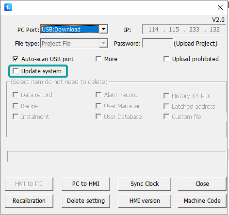
Upgrade system
After enable the Upgrade System, the on-screen system HMI V1.0 can be upgraded to the new system HMI V2.0.
Precautions
- Do not cut off the download cable and power cable during the upgrade process, otherwise the upgrade may fail and the system cannot be accessed.
- After the upgrade is successful, the data and projects on the screen will be deleted, please remember to backup first.
- After upgraded, it cannot be rolled back to the previous version.
- This upgrade will only upgrade the system and will not download the project. After restarting, it will prompt "The project is incomplete or the version is too low". The project needs to be upgraded and then downloaded again.
- After the upgrade is successful, some functions will be affected and cannot be used, as shown in the table.
- Specifically as shown in the table.
| Missing functions & Alternatives after upgrade | |||
|---|---|---|---|
| Category | Function | Affected Models | Alternative |
| Features | Camera (USB) | 8000, 9000, 8000+, 9000+ | |
| Multi-link interconnection | 3000, 8000, 9000, 3000+, 8000+, 9000+, 3000i | ||
| Cloud SMS | 8000, 9000, 8000+, 9000+ | ||
| Custom Object | Custom_MoviePlayer | 9000, 9000+ | |
| Custom_Dobby_Pattern | 3000, 8000, 9000, 3000+, 8000+, 9000+, 3000i, 3000ie | ||
| Custom_Glass | 3000, 8000, 9000, 3000+, 8000+, 9000+, 3000i, 3000ie | ||
| Custom_HisTrend | 3000, 8000, 9000, 3000+, 8000+, 9000+, 3000i, 3000ie | ||
| Custom_Tank | 3000, 8000, 9000, 3000+, 8000+, 9000+, 3000i, 3000ie | ||
| Custom_Weather | 3000, 8000, 9000, 3000+, 8000+, 9000+, 3000i | Weather forecast Lua script interface | |
| Custom_DCTU_WaterRes | 3000, 8000, 9000, 3000+, 8000+, 9000+, 3000i | ||
| Custom_DCTU_H212EPP | 3000, 8000, 9000, 3000+, 8000+, 9000+, 3000i | ||
| Custom_CsvTable | 3000, 8000, 9000 | ||
| Tool | LAN monitoring software (HMI Monitor System) | 3000 | Webpage monitoring |
| VNC | 3000i, 3000ie, 3000ig | Webpage monitoring | |
| Smart APP | 8000, 9000, 8000+, 9000+ | V-Net APP | |
| Data Upload Tool | 3000, 8000, 9000, 3000+, 8000+, 9000+, 3000i, 3000ie | PI Record Upload Tool | |
| PIRemote | 8000, 9000, 8000+, 9000+ | V-NET Access Client | |
Upgrade Method
Method 1: Open Download tool, and check the box of Upgrade System when downloading, as shown in the following figure:
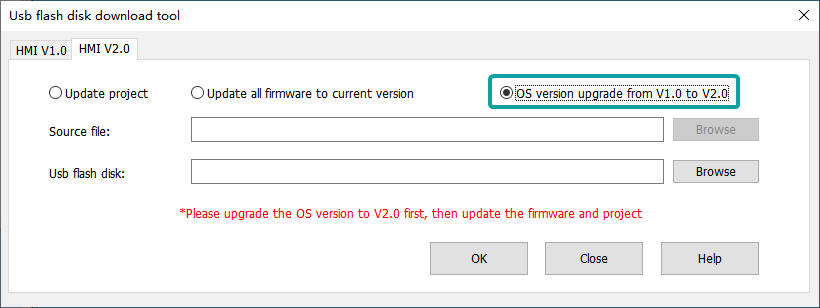
Method 2: When creating a Udisk upgrade image, check the box of "OS version upgrade from V1.0 to V2.0" from the tab "HMI V2.0", as shown in the following figure:
HMI Setting(V9.0)
Enter backend
1.Long press the upper right corner of the screen to enter the backend.
2.Special register

| Register | Meaning | How to use |
|---|---|---|
| HSW884 | Enter the backend network setting page | =1:Enter the backend network setting page |
3.Floating
After download the project,the floating will appear in the screen.Click the floating to enter the backend.
Backend page
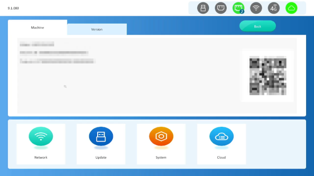
- Machine:
- Model: the model of HMI
- Serial NO. : the serial number of HMI
- Machine ID: the machine code of HMI. The first 20 digits are the serial number.
- Version: Display the version information of the HMI
- The icons in the up-right corner are USB-A device, Ethernet1 network, Ethernet2 network, WIFI network,4G network and cloud access network status respectively. Green indicates that the device/network is available. Black indicates that the device/network is unavailable.
Network
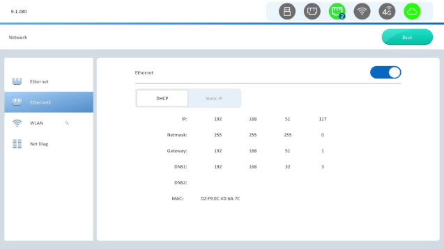
Ethernet:
If the Ethernet function is enabled and the network connection is normal, the IP address and MAC address of the HMI are displayed.
static IP: Click the Statice IP,customer can change the IP freely.
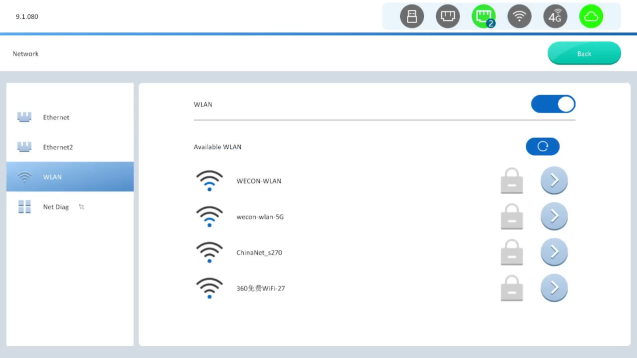
WIFI / 4G:
The HMI with WIFI module or 4G module will display WIFI/4G configuration
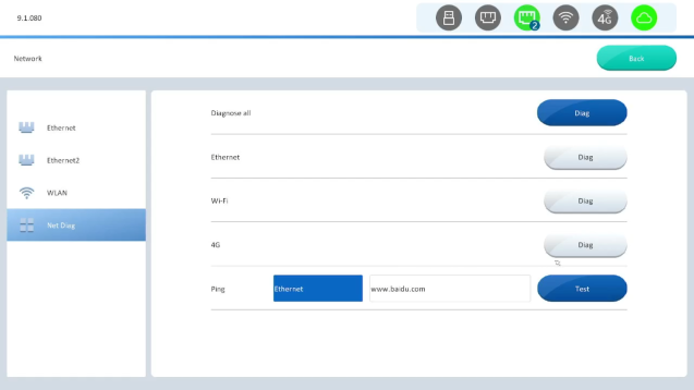
Net Diag:
Detect the Internet status of each network card separately
System
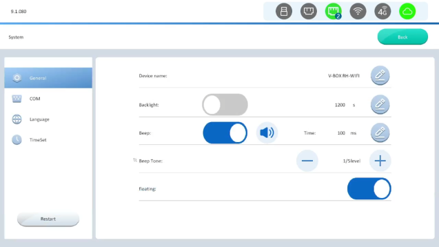
General:
settings of the system include: Device name,backlight time, beep,beep tone,floating.
- Backlight time: Set the rest time after the HMI is not operated for a long time, the maximum is 3600 seconds.
- Beep: Activate and deactivate the beep.
- Beep time: 0 to1000ms. The beep time length can be adjusted.
- Beep tone: Adjust the beep sound, and five types are provided.
- Floating: Select whether to display the floating.
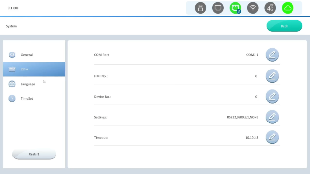
COM
COM settings include serial port number, HMI station number, device station number, serial port parameters, and timeout period. As shown in the picture below:
Do not change the settings at will. After modification, the device may fail to communicate.
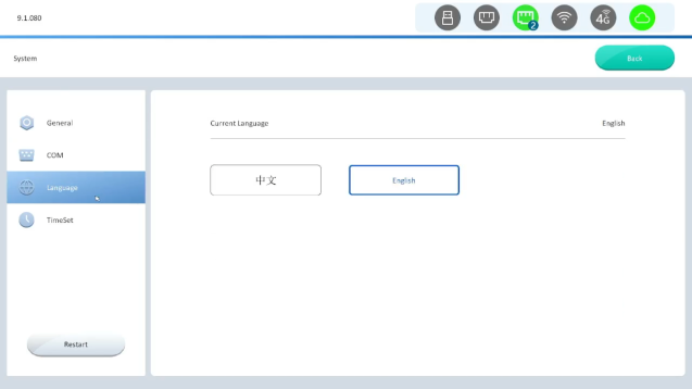
Language
- If the software display language is Chinese, the default language of the system is simplified Chinese. You can switch it to English in settings (as shown in the following figure);
- If the software is displayed in other languages, the system will display English by default, and cannot switch to English in the setting.
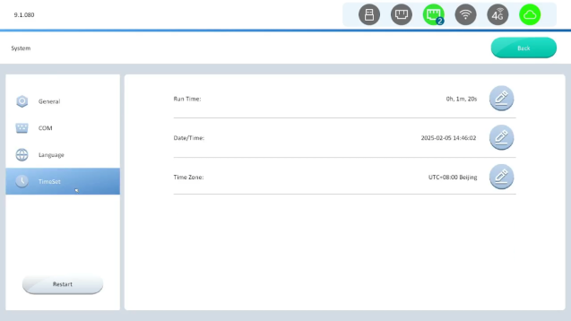
TimeSet
- Data/time: Display the current system time. Click the horizontal line can change it directly, and click save after modifying, otherwise the modification is invalid.
- Time zone: The legal area of common time standard, default "UTC+8:00 Beijing".
- Run Time:Calculate the time since the HMI was last powered on.
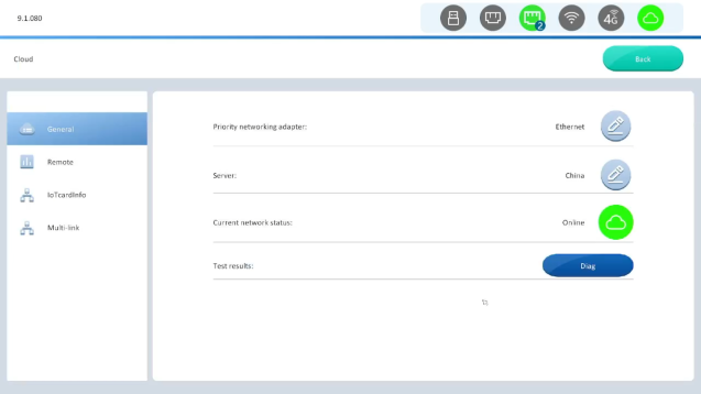
Cloud
- Priority networding adapter:Select the adapter to be used first when linking to the cloud.
- Server:Select the cloud server.
- Current network status:Green indicates that the device/network is available. Black indicates that the device/network is unavailable.
- Test results:Detect the Cloud status of each network card separately
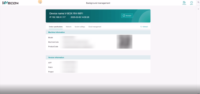
Remote backstage
After enter the 'IP+:9091'.We can access the HMI remote setting page.The remote setting is synchronized with the system setting. When the data of the remote setting is changed, the status of the HMI will be modified synchronously
Default account and password:
Account:admin
Password:888888
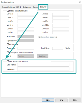
Account setting
[Project setting]→[Security]→[LAN Monitoring Secunity]
Remote (HMI setting in V10.0)
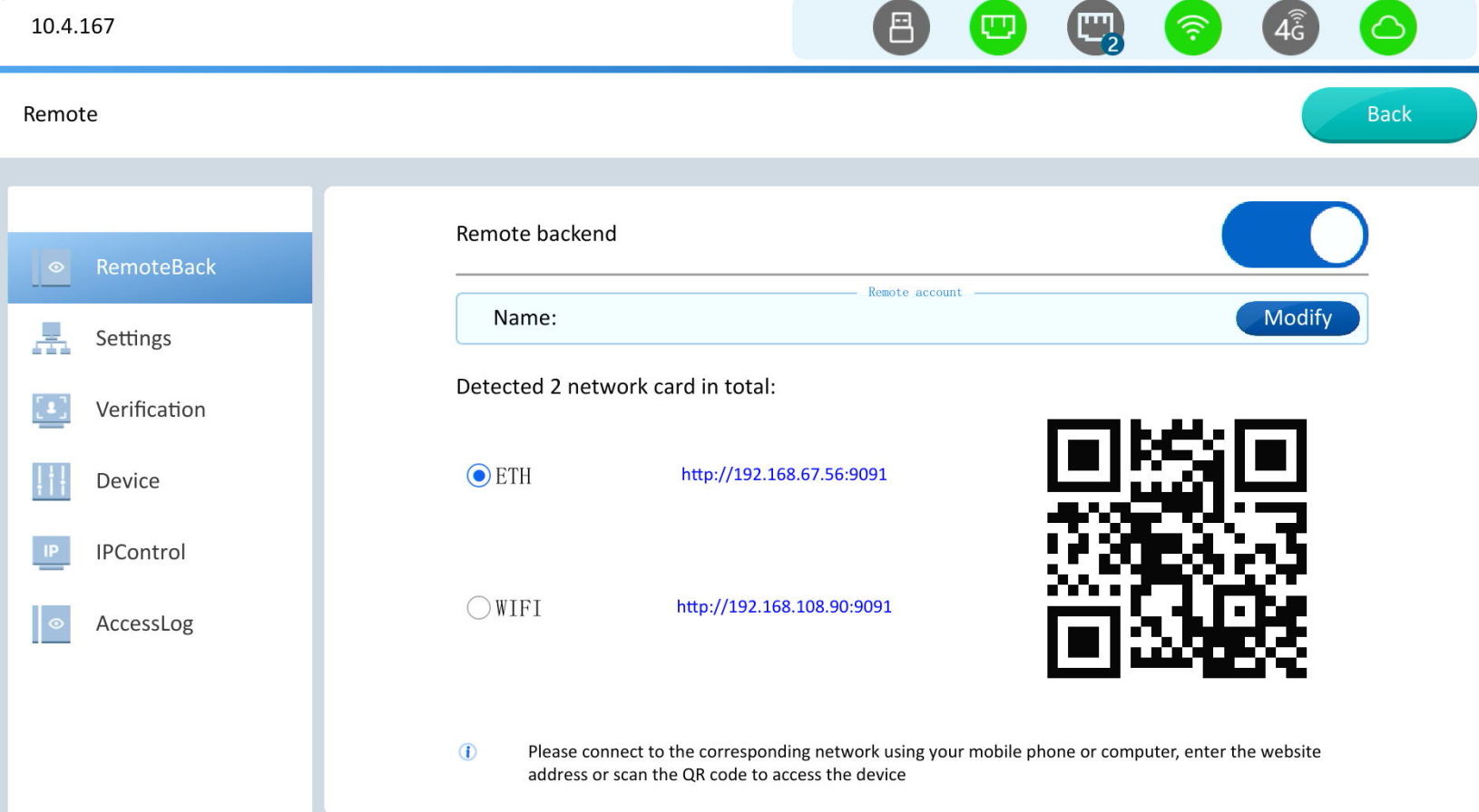
Remote Management: Mainly used to ensure the security of remote access and operations. The interface includes: remote settings, access verification, device control, IP restrictions, and access logs.
Remote Back
Remote backend: Restrict remote access to the backend. If closed, remote access to the backend is not allowed.
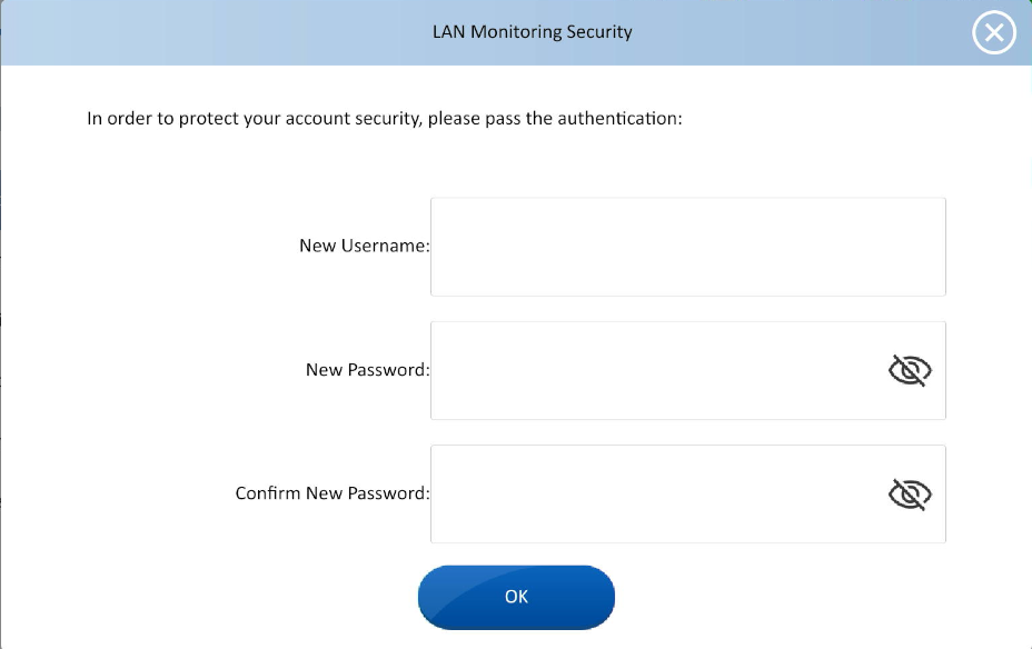
Name: Modify user name and password of remote backend.
Network QR code: There will be generated QR codes that HMI is connecting to the network.
Name configuration interface:
Setting
Exclusive Mode: Only one client is allowed to remotely access the device at the same time.
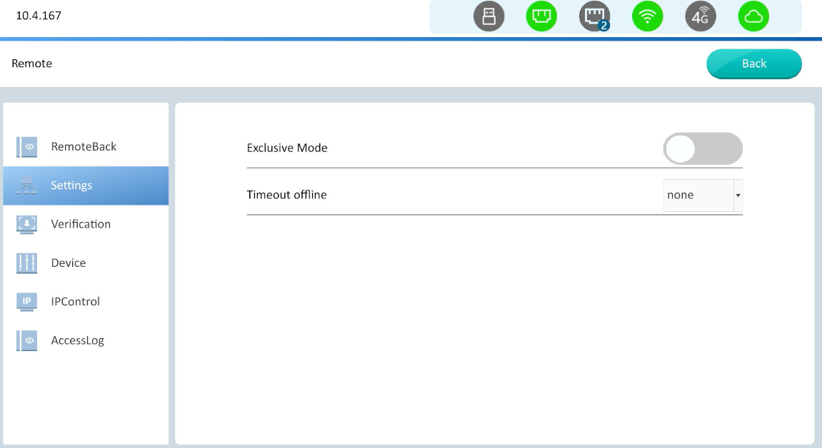
After entering exclusive mode, press and hold a blank area on the device for 10 seconds to enter exclusive mode.
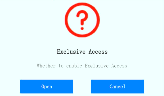
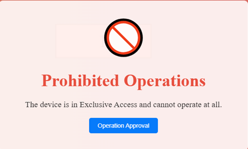
After enabling, other clients will see the following interface. If they want to continue accessing the device, they will need to apply for access.
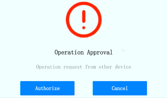
When a device submits an application, the current exclusive device will display the following screen. If clicking Authorize, the exclusive permission will be transferred to the device that submitted the application.
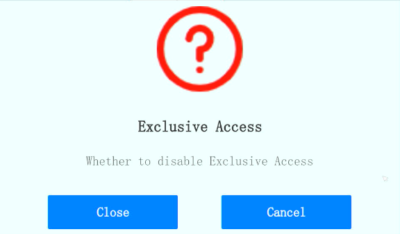
Press and hold for 10 seconds in the blank space again to turn off exclusive mode.
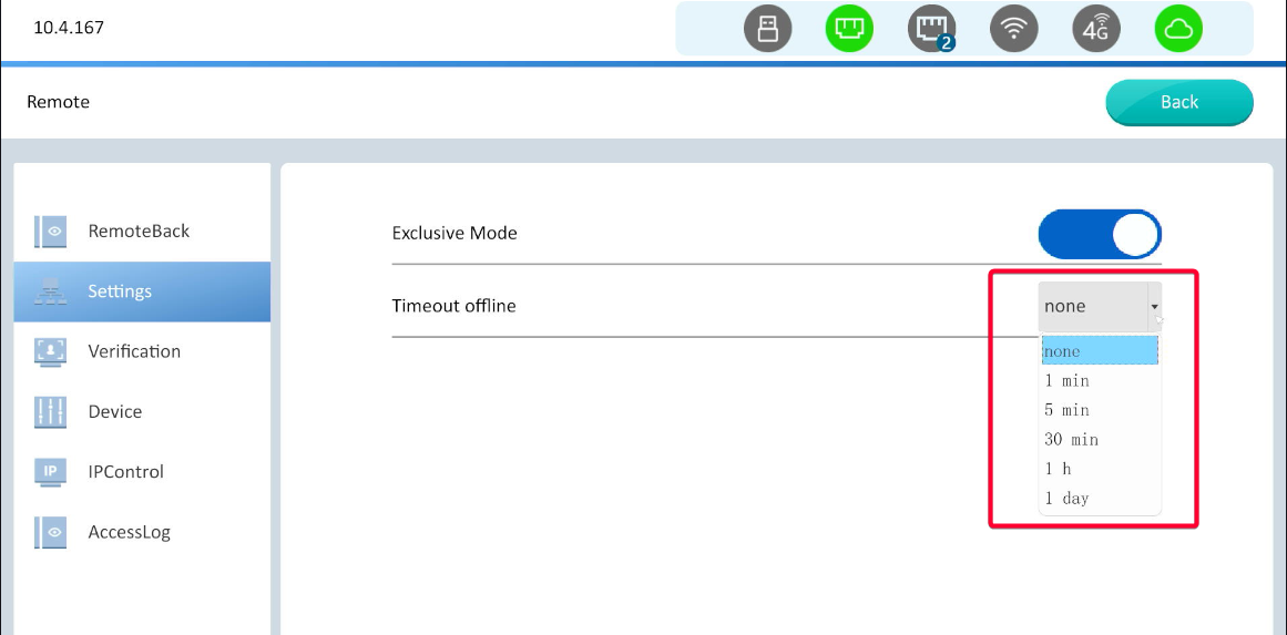
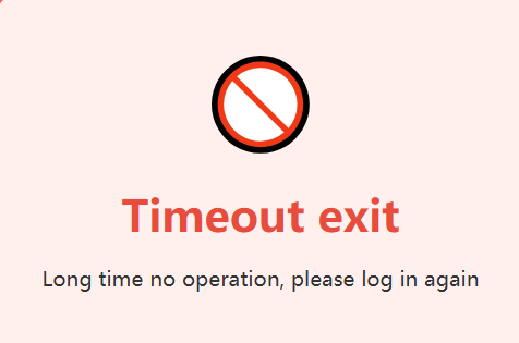
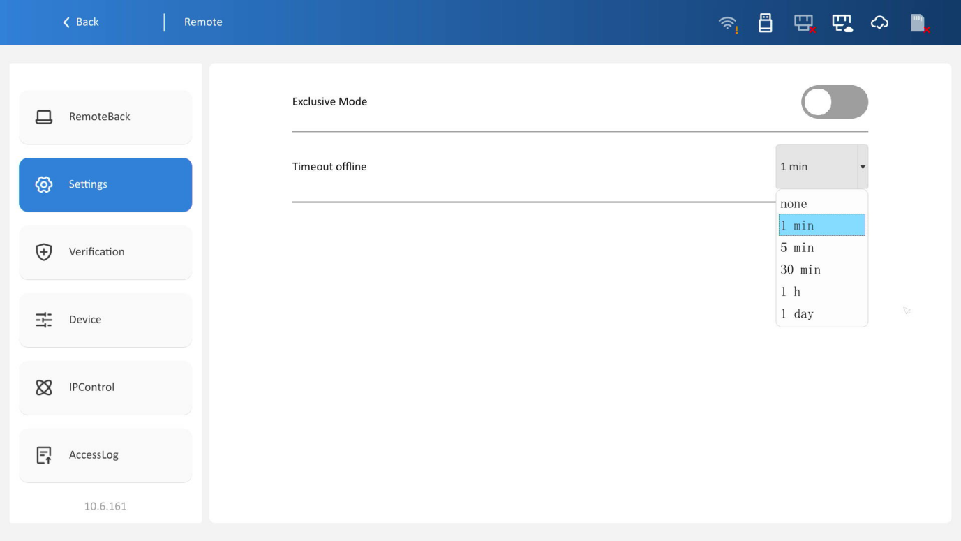
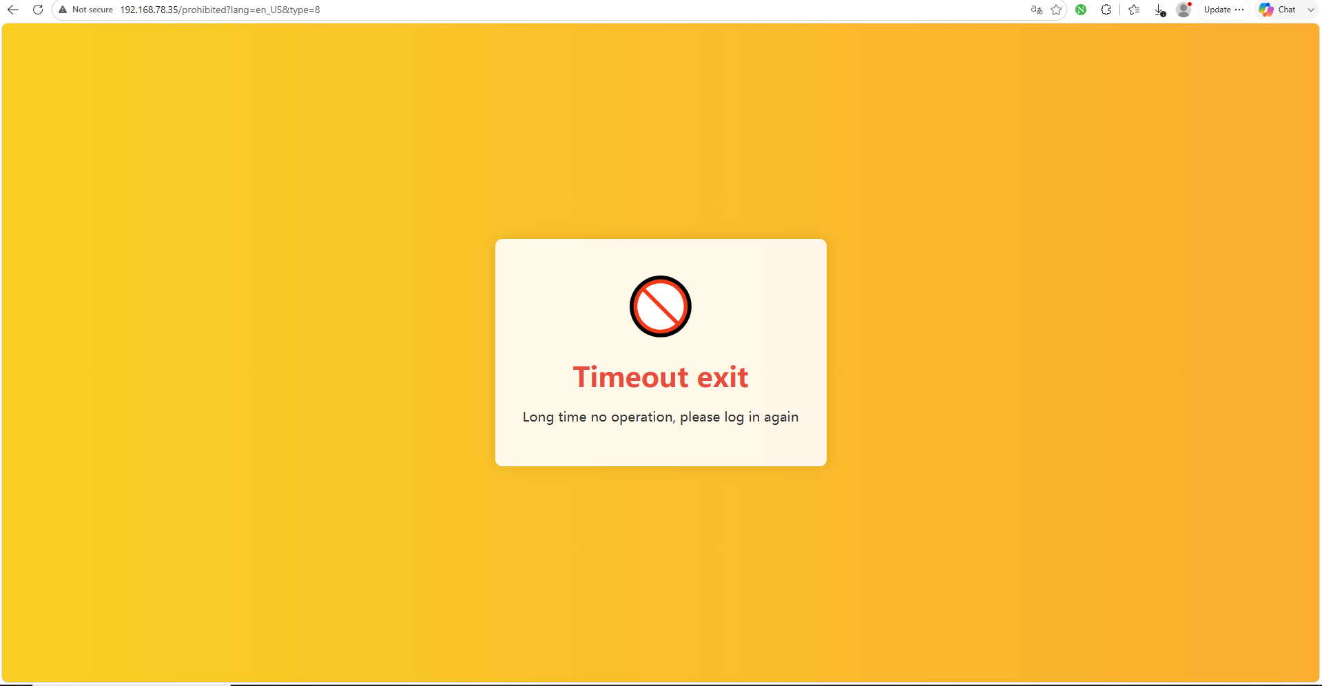
Timeout offline: If the device is not operated for a specified period of time, the remote client will be forced to log out.
Timeout exit interface:
Special address
| Special address | Function |
| HSW1923 | Enable Exclusive Mode =0, Disable =1, Enable |
| HSW11750 | =1 , English =2 , Chinese |
Verification
The access verification function is enabled, which can perform access verification processing on the LAN monitoring and enhance the security of the LAN monitoring.
Remote account: The user name and password need to be set for the first time. By setting the user name and password, the user can log in to the LAN monitoring securely with the set account and password.
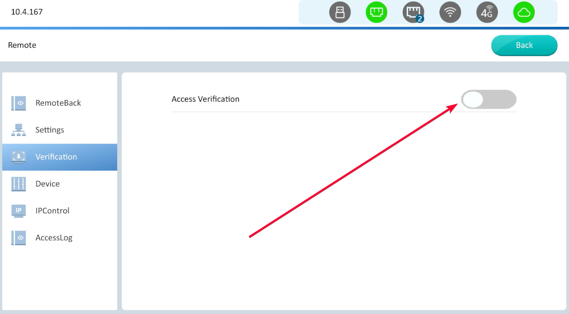
Modify: Reset user name and password.
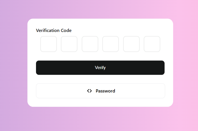
Verification Code: Users enter LAN monitoring via a verification code. You can set the validity period of the verification code using different verification code types.
Type:
1.Single: The verification code is valid for a single use and automatically refreshes after a single use.
2.Single Day: The verification code is valid for a single day and automatically refreshes 24 hours after being used.
3.Permanently: The verification code is valid for a long time and does not automatically refresh.
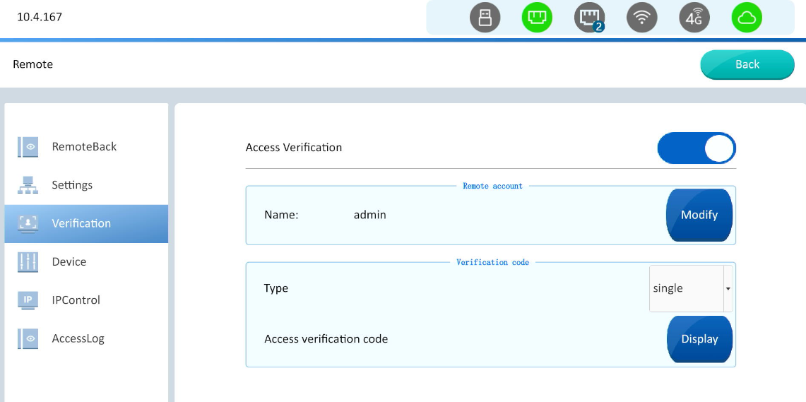
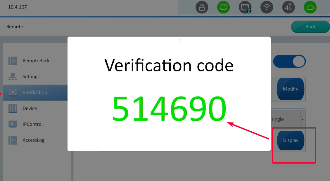
Display: To view the current verification code content
Enter HMI IP address in the browser, and login page will pop up. Enter username and password to access LAN monitor.
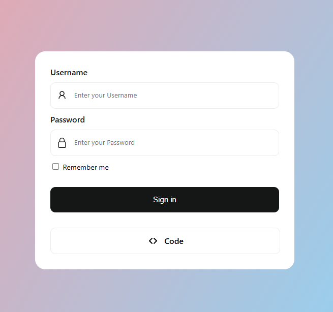
Click "Code" to verify the login in the form of a verification code
Device
New device allows access : is enabled by default. If it is disabled, new devices (devices that have not been accessed) will not be allowed to access.
The device name, IP address, and online status of devices that have been accessed can be displayed. The interface is shown in the figure below.
Edit interface
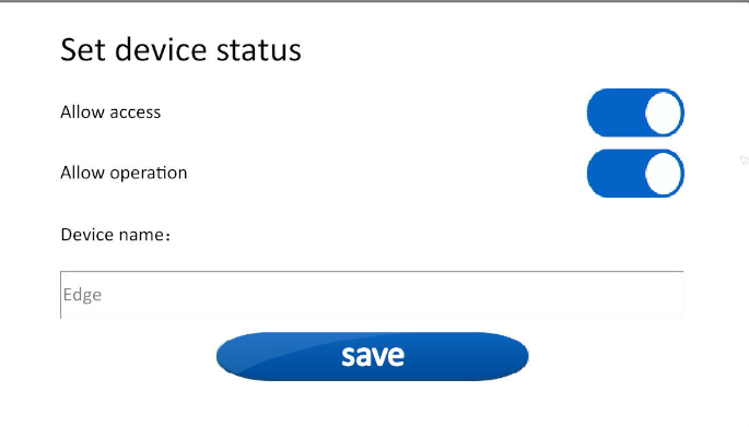
Click "Edit", and the device setting status window will pop up, where the access rights and operation rights for the device can be set , and change the device name.
IPControl
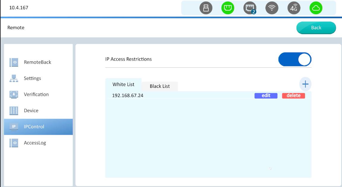
Switch between Black List and White List. Control the access rights of clients with specified IP addresses.
White List: IP in the White List have access rights, while IP not in the whitelist cannot access.
Black List: IP in the Black List do not have access rights, while other IP are not restricted.
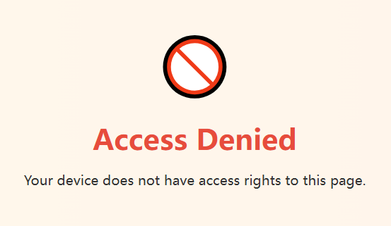
If IP is added to the blacklist, the access screen will be as shown below:
AccessLog
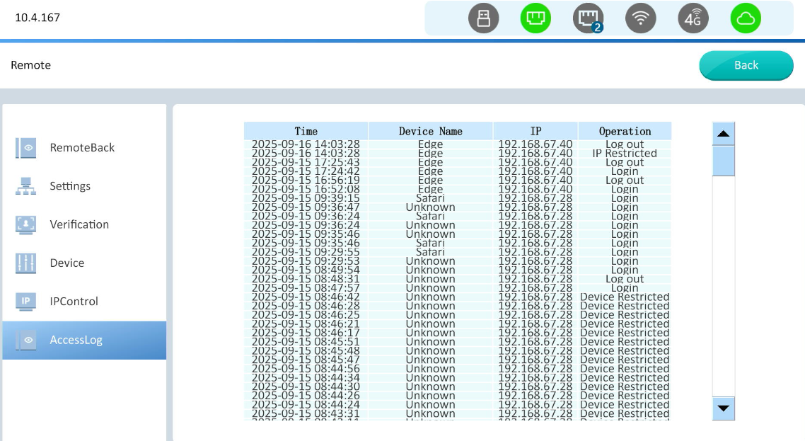
The access log function allows to view all client operation records, including time, device name, IP address, and operation, as shown in the figure below.
Operation Table
| Operation | Explanation |
| Login | Remote monitoring in progress |
| Logout | Exit remote monitoring |
| Incorrect Password | When logging into remote monitoring, the password entered is incorrect. |
| Incorrect Verification Code | When logging into remote monitoring, the verification code entered is incorrect |
| IP Restricted | During remote monitoring access, the following two situations may occur: 1. When IP access is restricted to Black List, the current device IP address is on the Black List. 2. When IP access is restricted to White List, the current device IP address is not on the White List. IP restricted access records will be recorded. |
| Device Restricted | During remote monitoring access, there are two situations: 1. When the new device access switch in the device control function is turned off, access is attempted using a browser that has not been used to remotely monitor the current HMI. 2. When the device control function does not have access permissions enabled. Restricted access records for the corresponding device will be recorded. |
Configuration interface (HMI setting in V10.6)
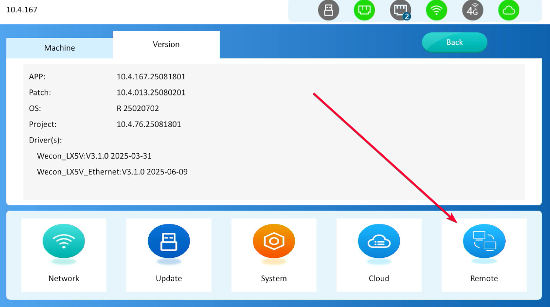
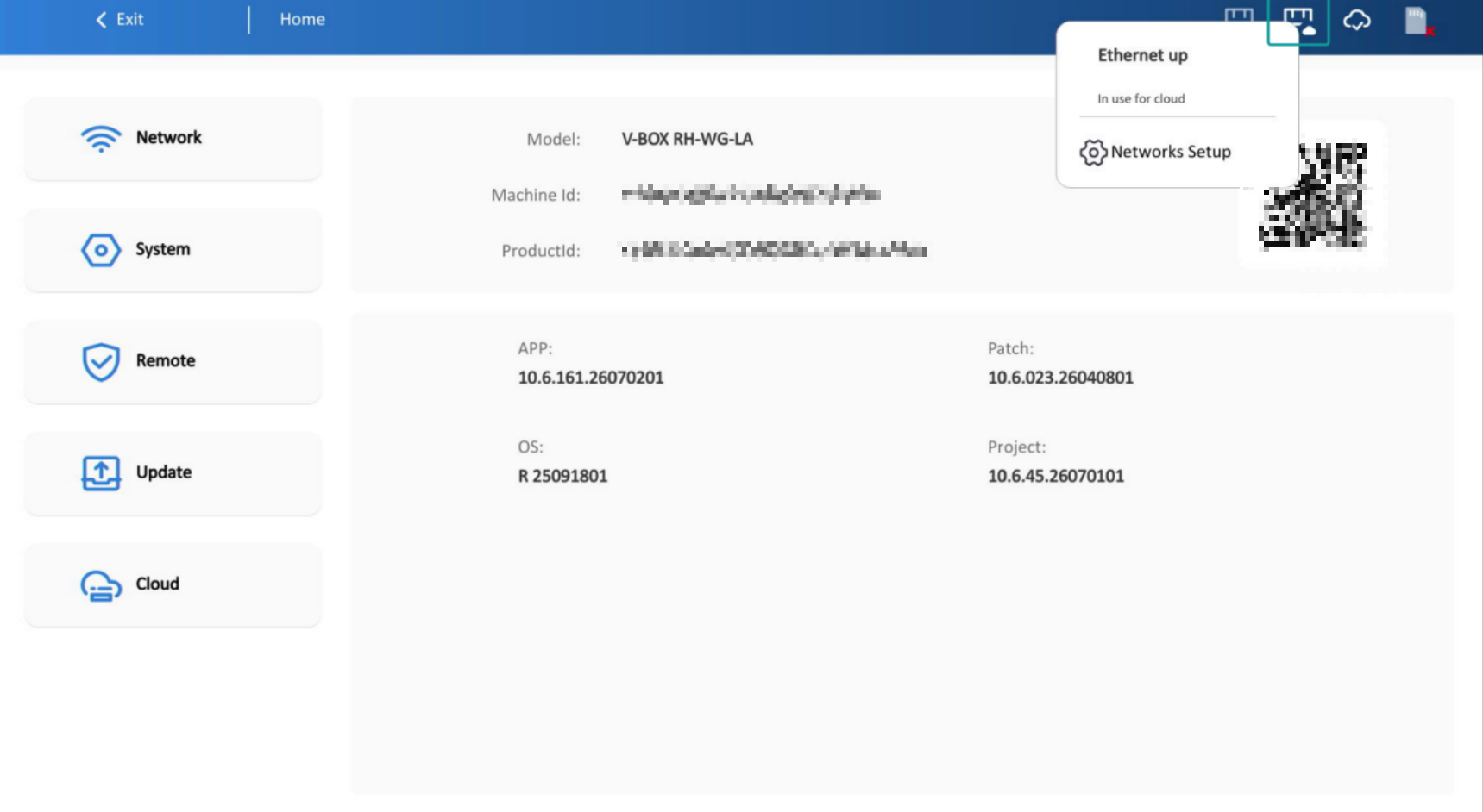
Enter the HMI configuration interface; the initial interface displays machine information and version information, as shown in the figure below:
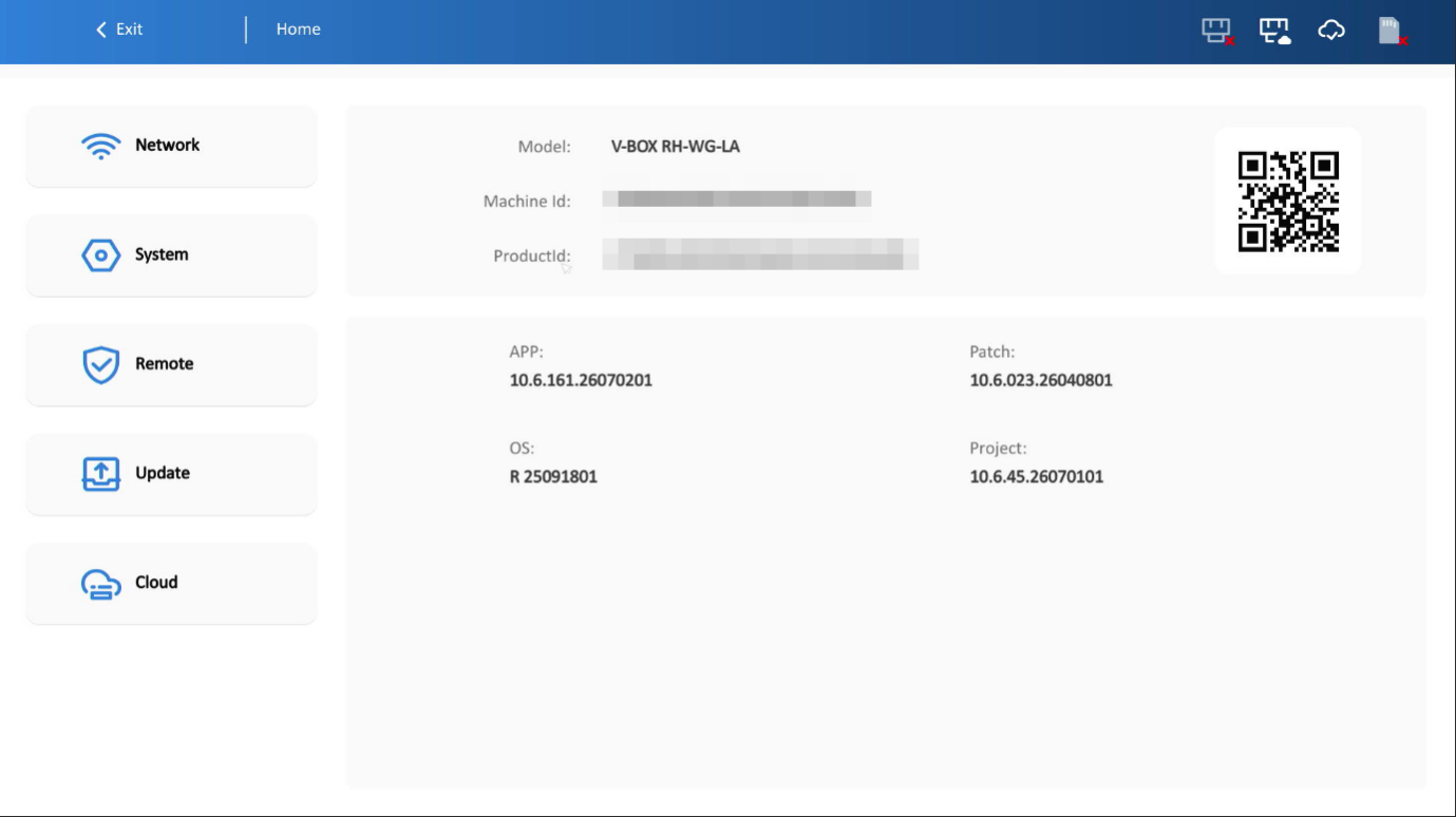
Device information
Machine information
- Model: HMI model
- Machine Id: HMI machine code; the first 20 digits are the serial number
- Product Id: HMI product code
Version information
Displays the current version information in the HMI:
APP: APP version information
Patch: Patch version information
OS: OS version information
Project: Project version information
Modbus_RTU_Winder: Driver version information
Top-right icons
Display statuses including Wi-Fi, USB-A device (see laser engraving on the back cover), Ethernet, cloud access network status, 4G network, multi-machine interconnection, etc. The meanings are shown in the table below:
| Icon | Description | Icon | Description |
 | WLAN connected but unavailable |  | WLAN connected successfully |
 | WLAN connected successfully and connected to the cloud via this network |  | USB-A device connected |
 | No Ethernet cable detected |  | Ethernet unavailable |
 | Ethernet connected successfully |  | Ethernet connected successfully and connected to the cloud via this network |
 | Connected to the cloud |  | No IoT card detected |
 | 4G network unavailable |  | 4G network connected successfully |
 | 4G network connected successfully and connected to the cloud via this network |  | Multi-link master mode enabled |
 | Multi-link slave mode enabled and successfully connected to the master |
Click the icon to view the current status description.
✎Note: The pop-ups for Ethernet, Wi-Fi, 4G, and multi-machine interconnection icons also support jumping to the corresponding setting pages.
Network management
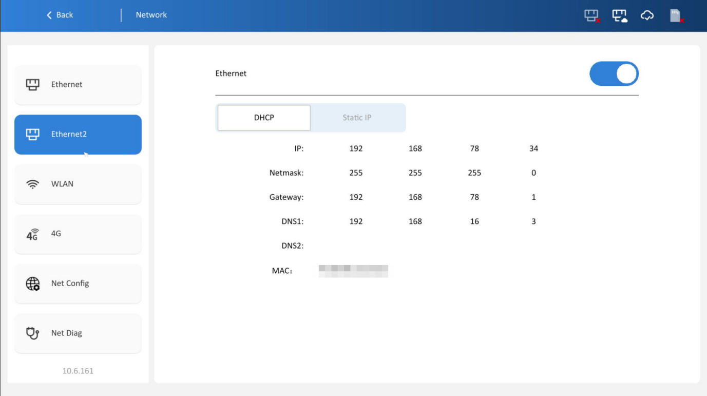
Ethernet
1. Enable the [Ethernet] function. If the network connection is normal, the HMI’s IP address and MAC address will be displayed, as shown in the figure:
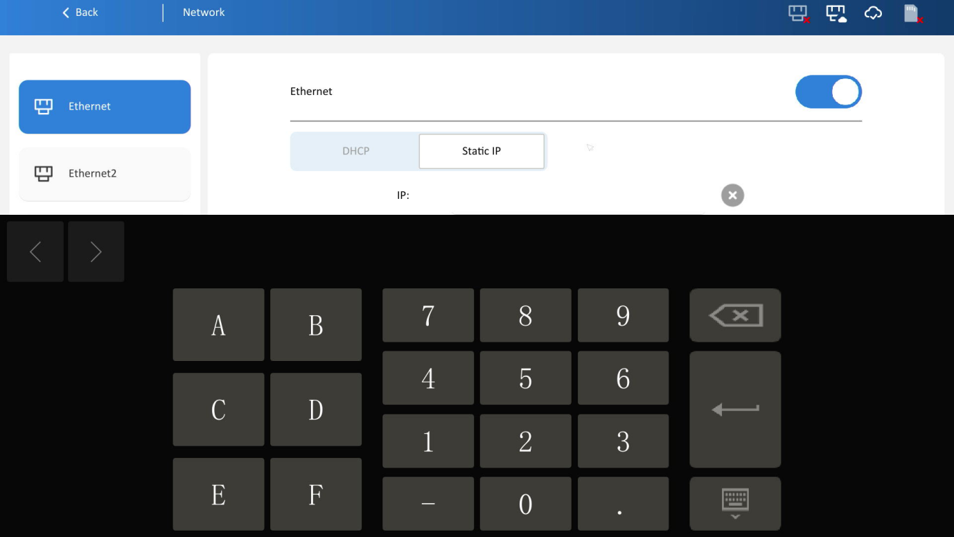
2.Static IP: Click the corresponding line to modify network parameters.
WLAN
Wi-Fi
Enable the [Wi-Fi] function . The HMI searches for Wi-Fi signals (the device must be equipped with a Wi-Fi module), select a Wi-Fi name, enter the password, and connect; The default is DHCP, if need to set a static IP, click anywhere on the connected Wi-Fi (shown the red box below). The configuration method is consistent with Ethernet settings.
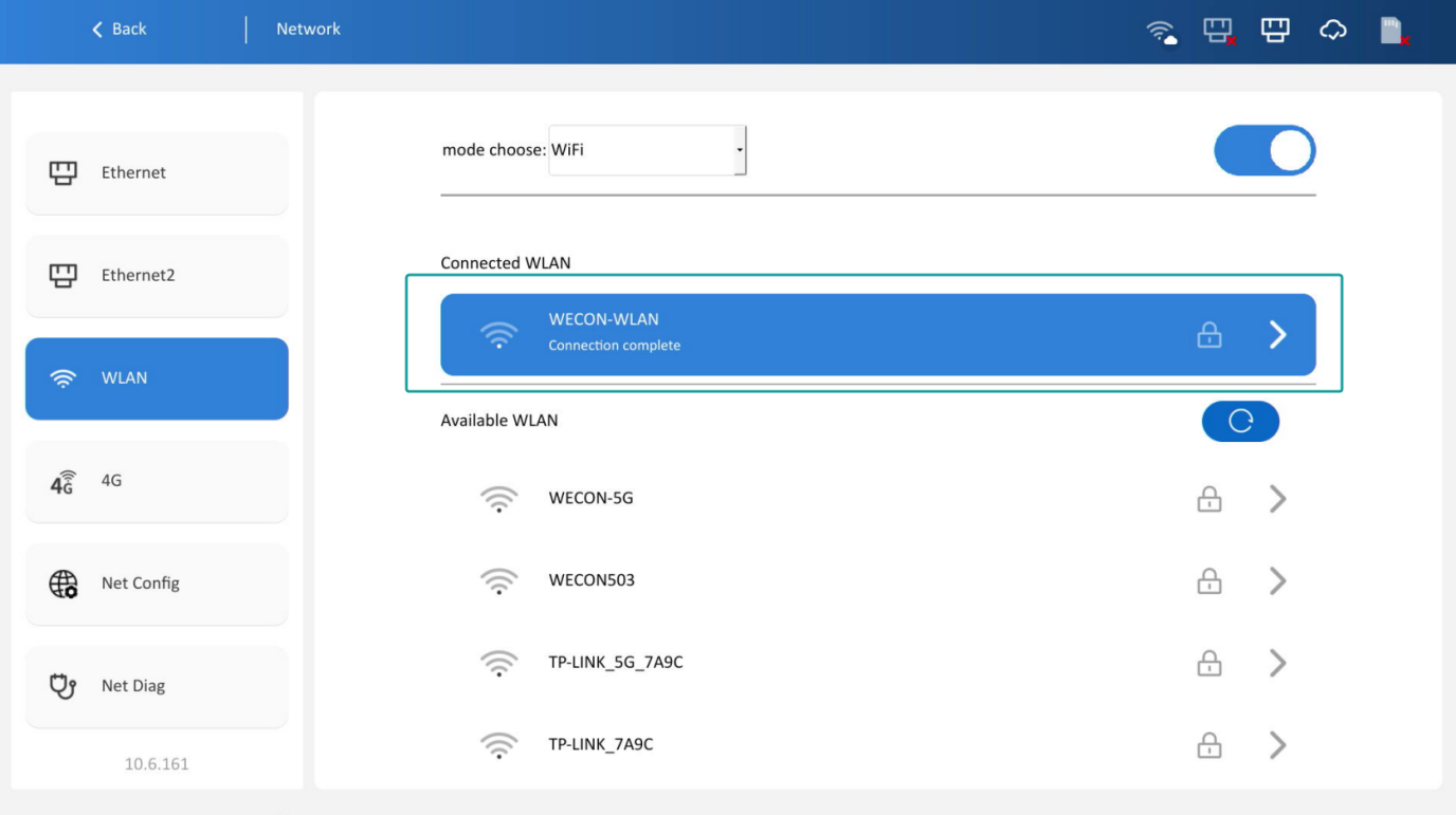
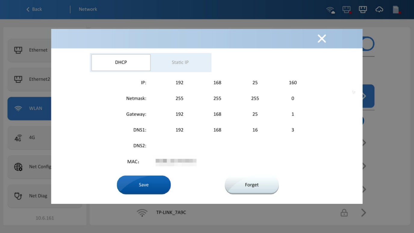
To disconnect this Wi-Fi connection, click [Forget] or connect to another Wi-Fi.
Hotspot
After enabling the [Hotspot] function, the HMI automatically creates a wireless network for connection by other devices.
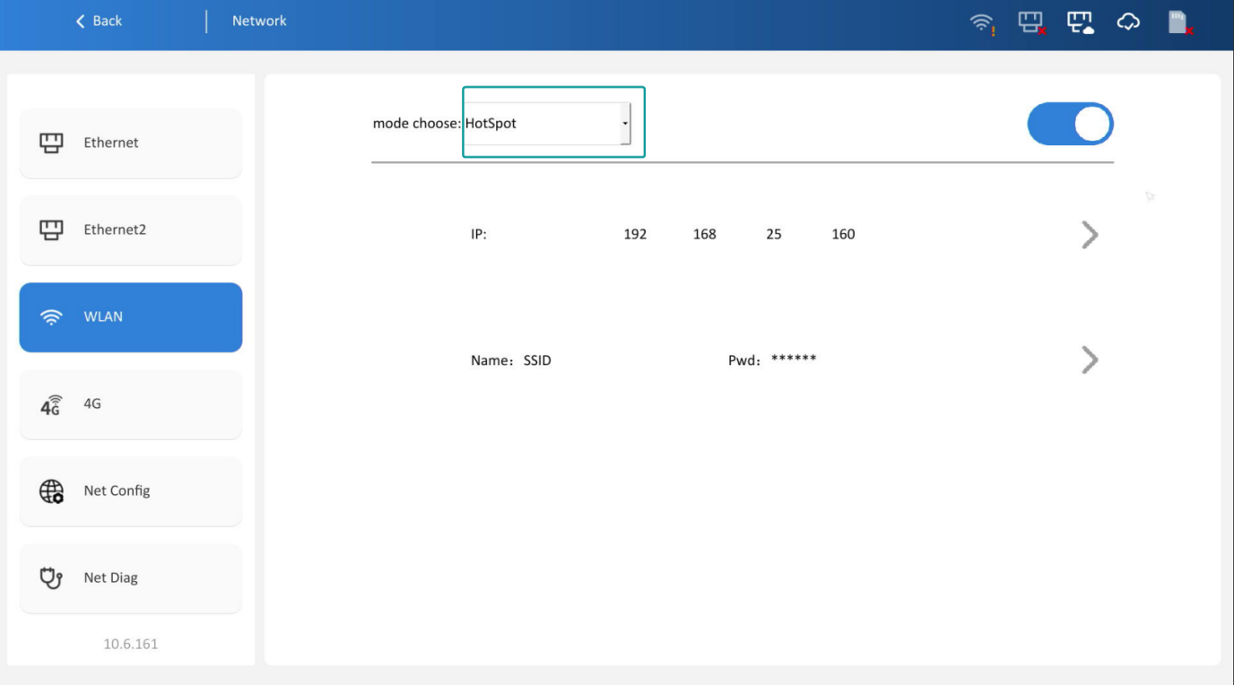
Click the red box button on the right side to configure the IP (the configuration method is consistent with Ethernet settings), name, and password of the hotspot.
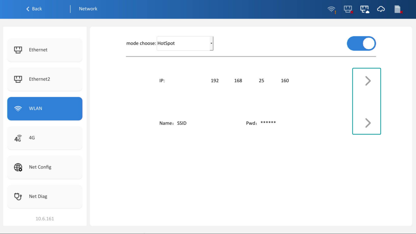
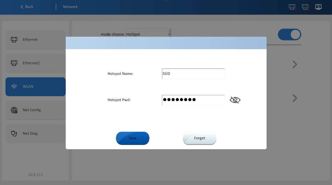
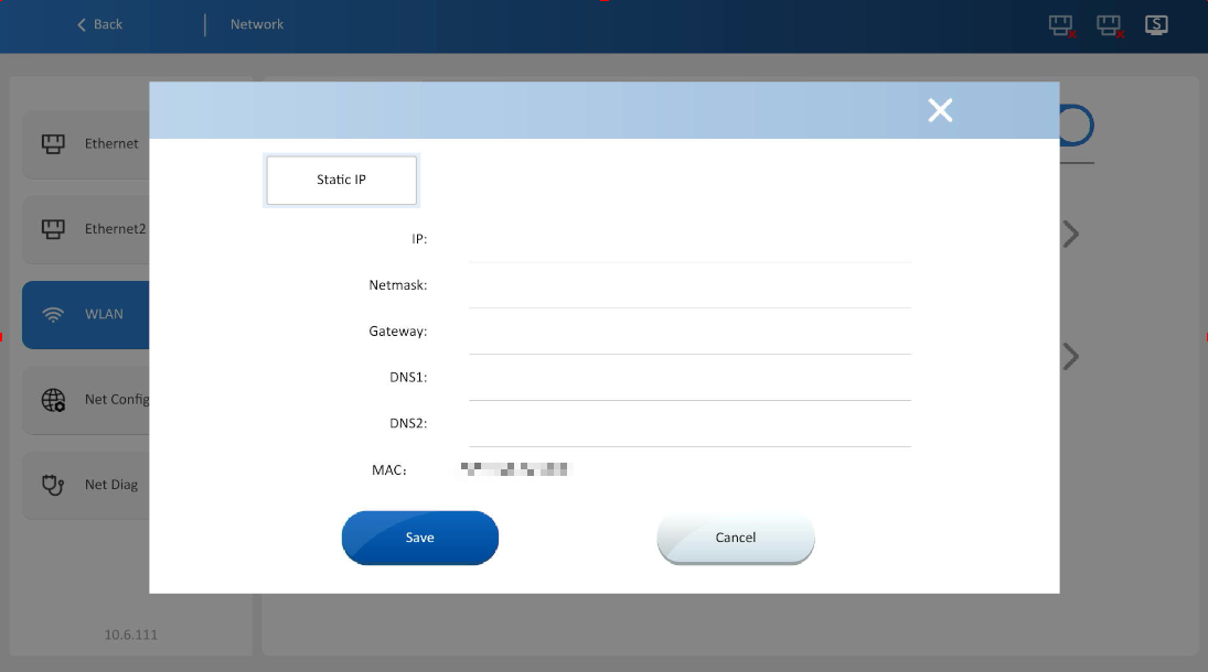
✎Note: The hotspot function is only supported on RH 8000ig and 9000ig models, the RH8000ig requires an additional patch to enable this function.
Network configuration
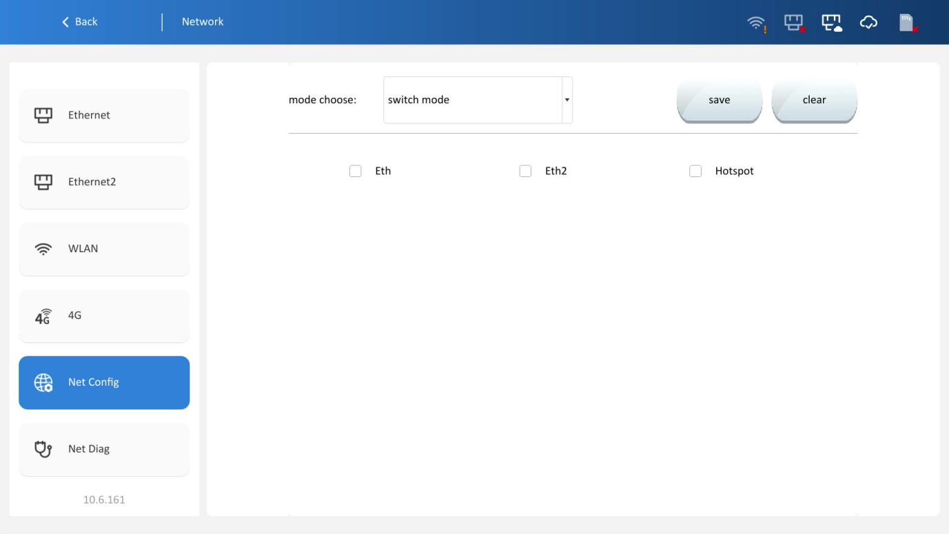
Switch mode
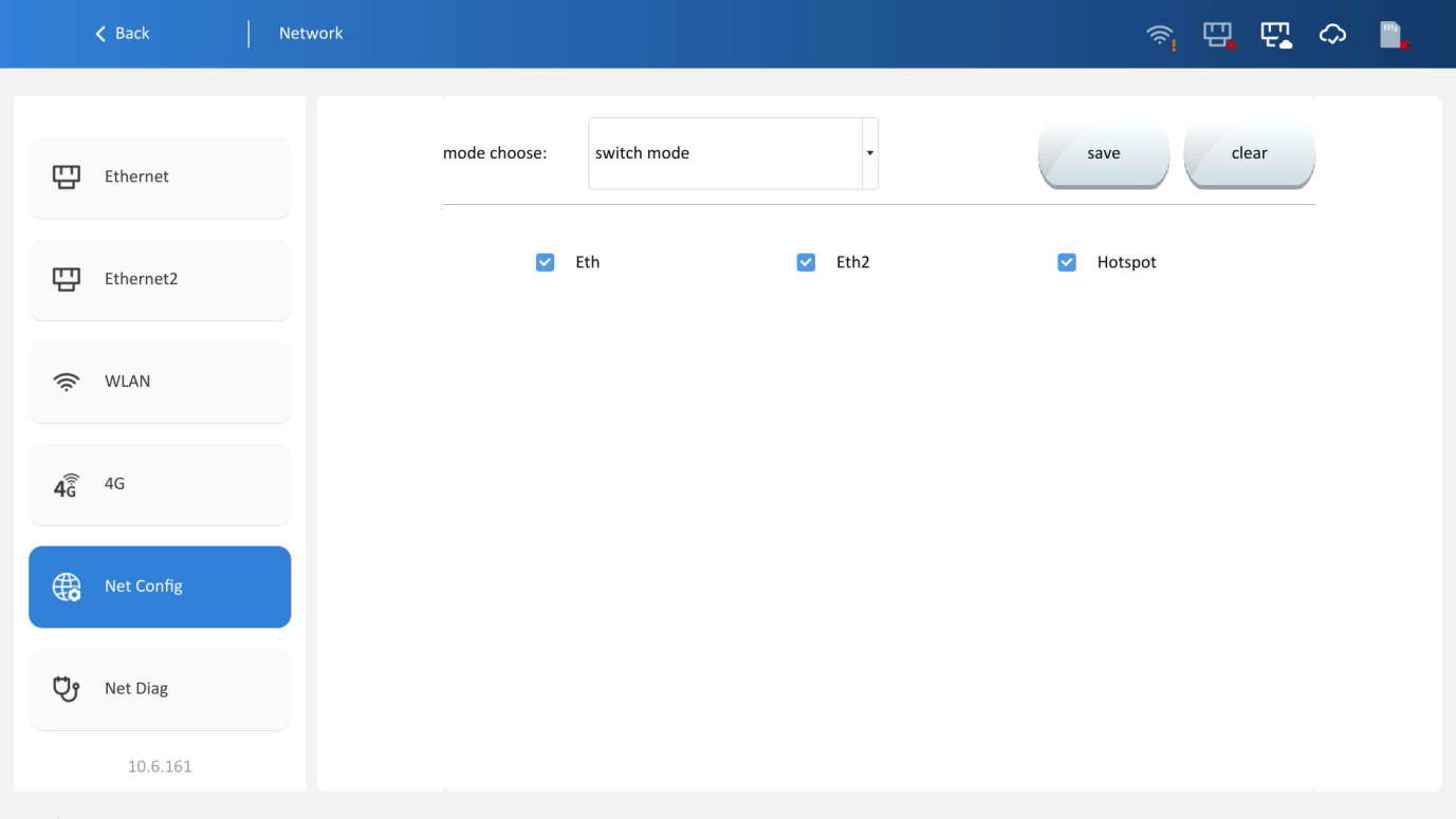
The device can be configured as a network switch to transmit data packets between multiple network interfaces. This mode is suitable for scenarios where multiple devices need to access the same network and communicate internally.
In switch mode, select at least two network cards (Ethernet, 4G, hotspot, etc.). After configuration and saving, the selected network cards will be assigned to the same network segment.
Router mode
The device can be configured as a router to transmit and communicate data between different networks. This mode is suitable for connecting multiple subnets or internal/external networks.
WAN port (Wide Area Network): Connects to the external network devices. Select a network card (Ethernet, 4G, Wi-Fi) for WAN.
LAN port (Local Area Network): Connects to internal network devices. Select a network card for LAN, configure IP address and subnet mask, and enable DHCP if needed to auto-assign IP address to internal devices.
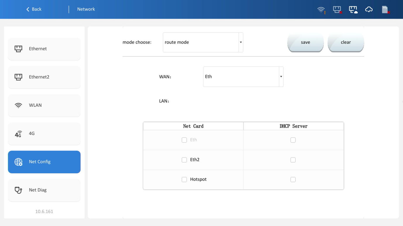
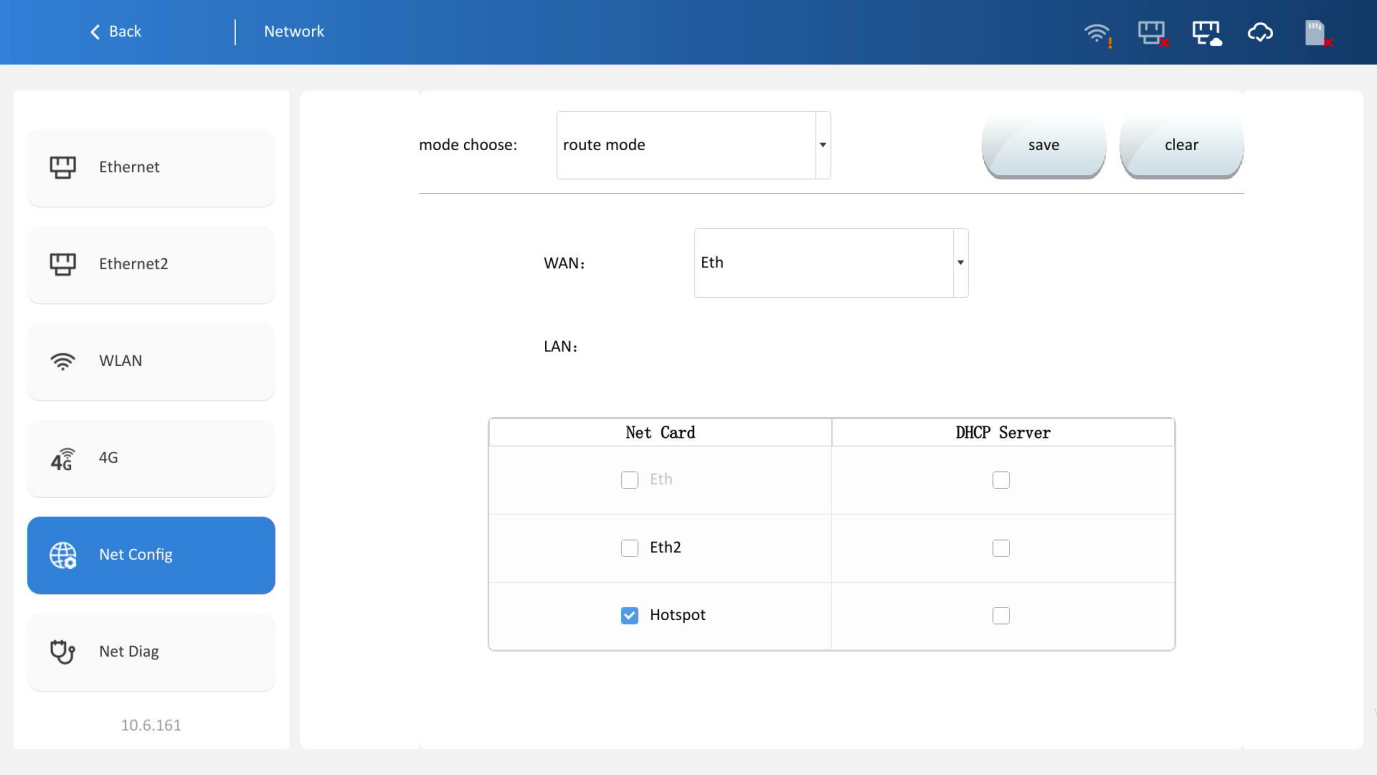
✎Note: If the device cannot obtain an IP address for an extended period after switching from switch mode to router mode, the DHCP server may still be retaining the previous IP address lease. Resolve this by re-plugging the Ethernet cable or restart the Ethernet interface.
4G
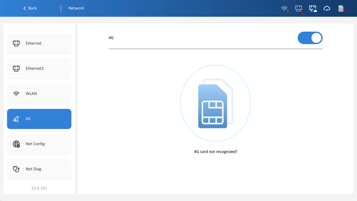
Insert a 4G card into the device and enable the [4G] function (the device must be equipped with a 4G module).
APN: Use the default APN in most cases; manually configure only when necessary.
Network diagnosis
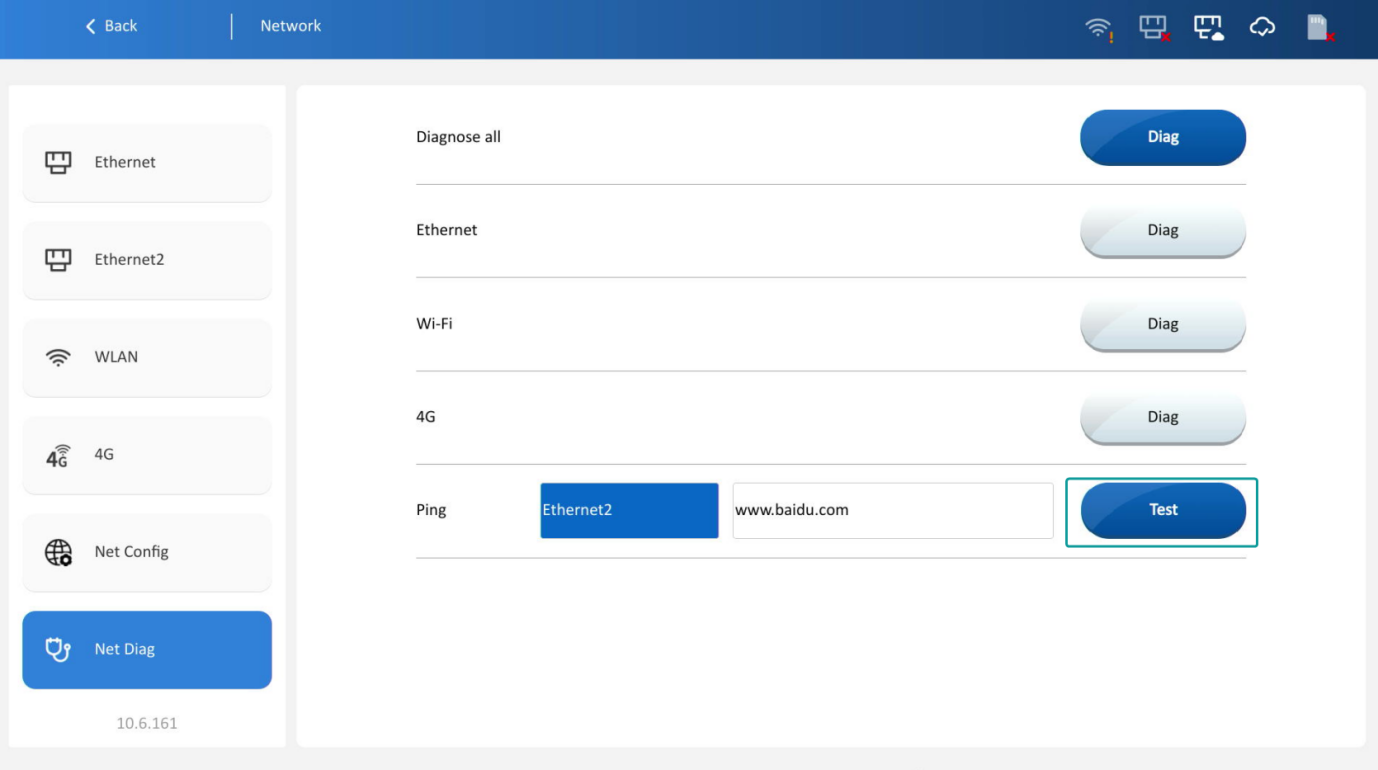
Detect and analyze network connection status to troubleshoot faults. Select full diagnosis or single-network-type diagnosis, and the diagnosis results will be displayed in the window, as shown in the figure below:
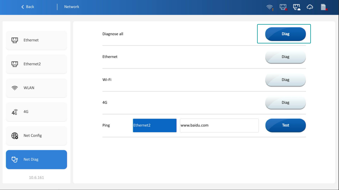
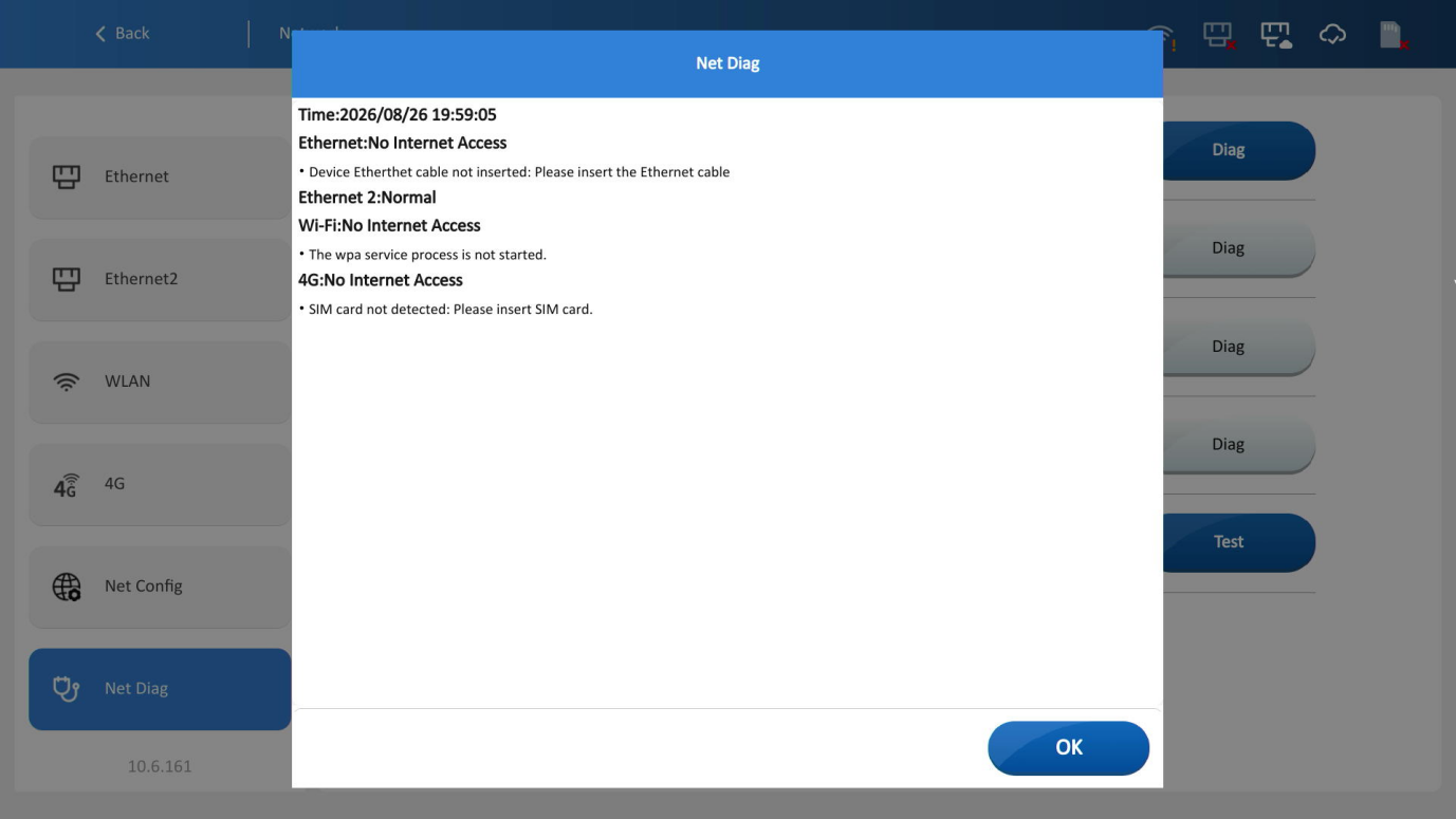
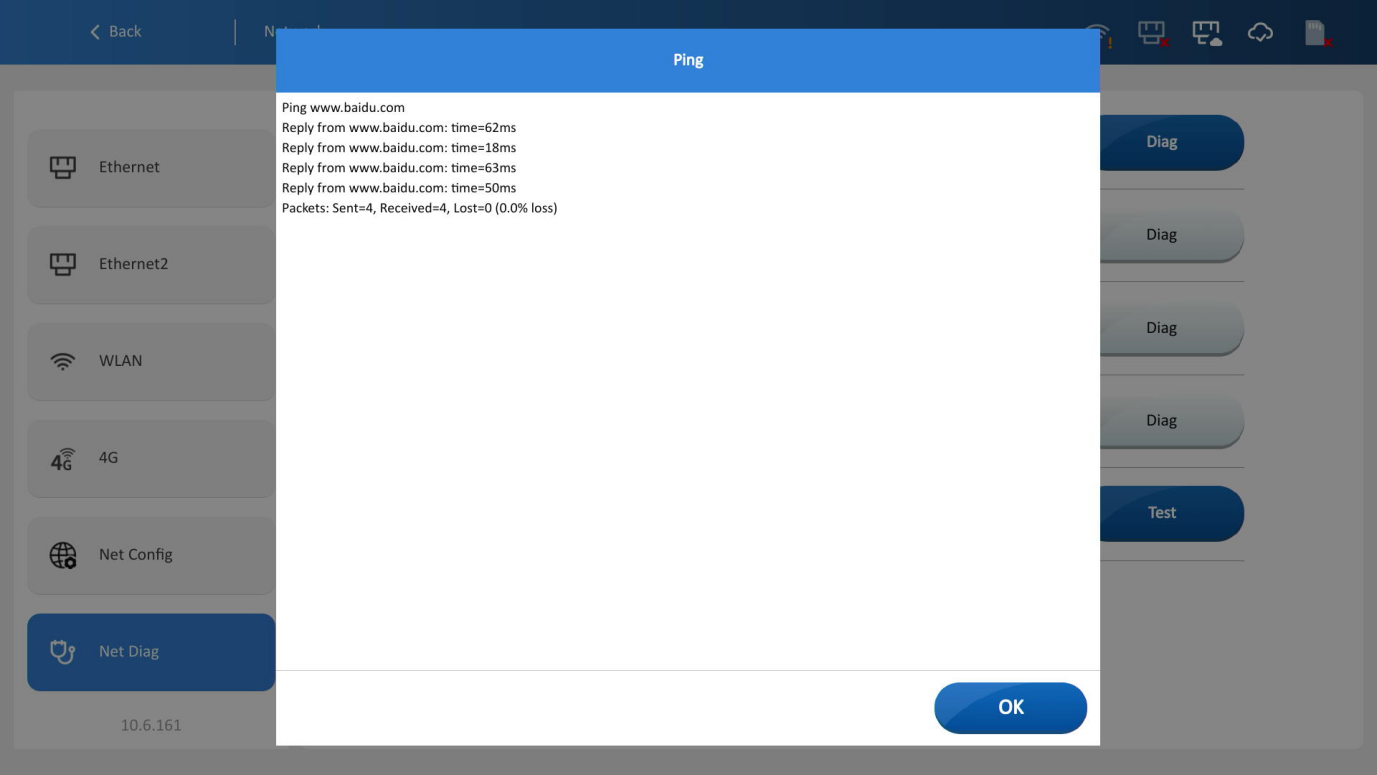
Click the test button on the right side to check the connection status between the device and target address.
System settings
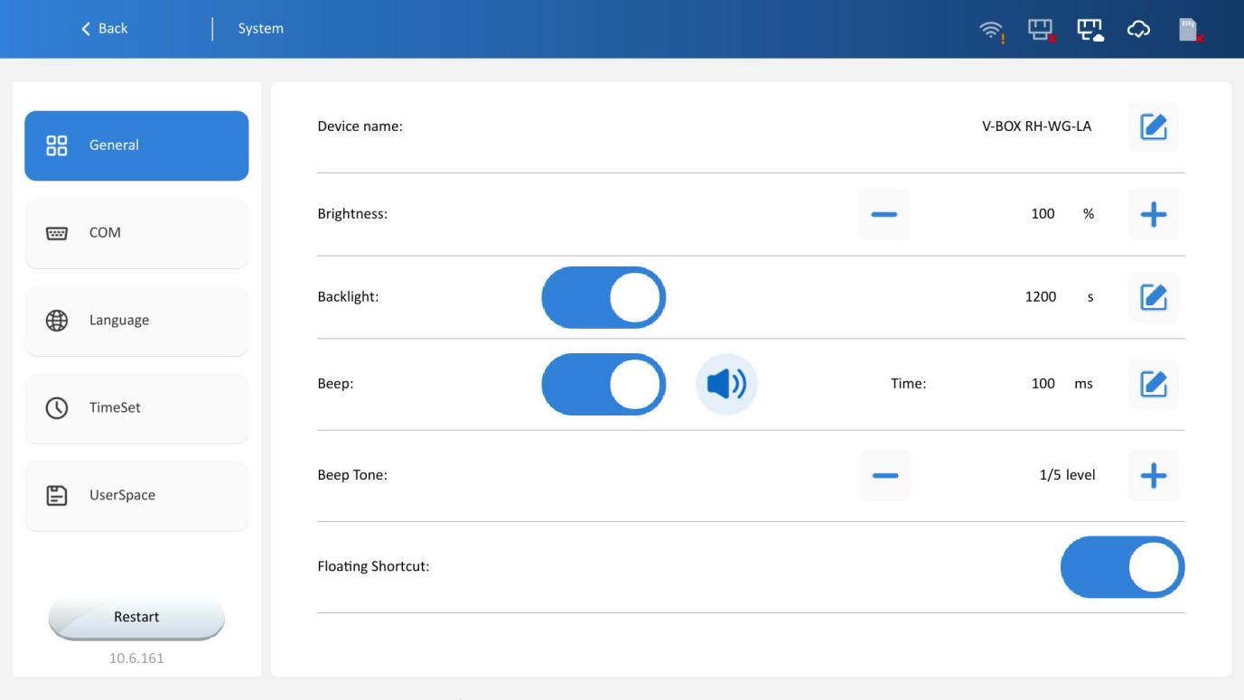
The [System settings] interface includes basic settings, communication settings, language, time settings, and storage space.
Basic settings
Device name: Set the HMI name
Backlight brightness: Adjust screen brightness
Backlight time: Set the screen-off time when there is no operation on HMI. (up to 3600s)
Beep: Enable/disable the buzzer; Time: Buzzer time adjustable 1~1000 ms.
Beep tone: Five adjustable frequencies
Floating shortcut: Enable/disable; when enabled, a floating shortcut will be displayed in the top-right corner of the HMI project screen for quick access to the HMI configuration interface.
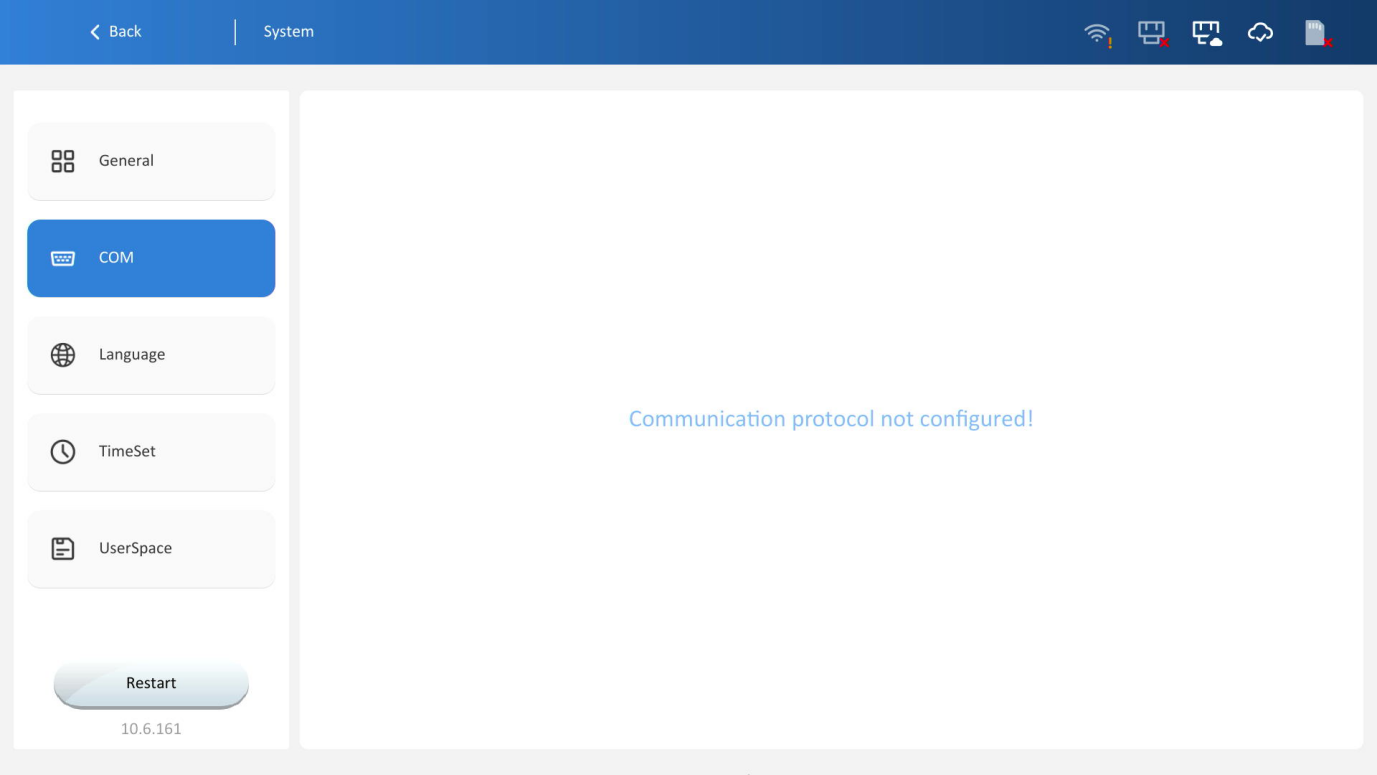
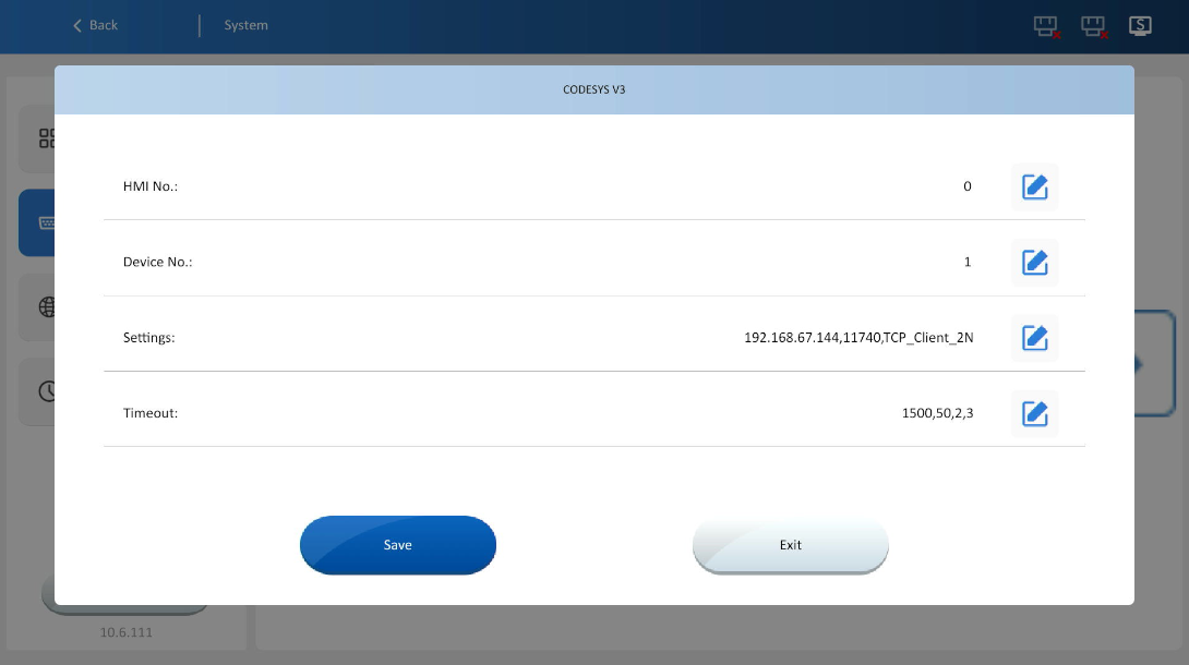
Communication settings
Select the serial port to configure and double-click to enter settings: HMI station number, device station number, communication parameters (serial port parameters), timeout.
✎Note: Do not modify serial communication settings unless necessary. Changes may cause communication failure of the device.
Click [Save] after finishing modifications.
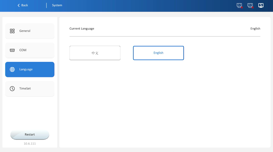
Language
Click to switch the background interface language. Chinese and English are supported, as shown below.
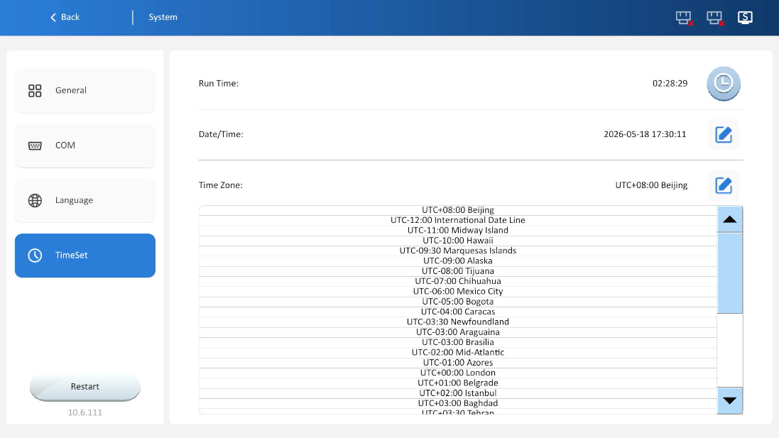
Time settings
Time settings include: Running time, Date/Time, and Time zone.
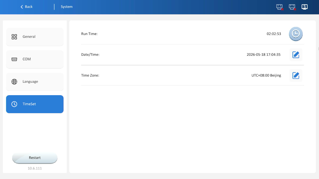
Run time: Display the operating duration after device startup.
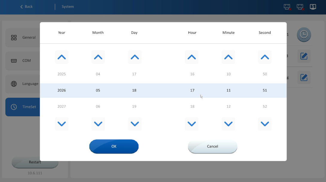
Date/Time: Shows the current system time. Click the button on the right to edit directly. Click [OK] after modification, otherwise the modification will be invalid.
Time Zone: Standard time zones divided by longitude. Default is "UTC+08:00 China". Click the button on the right to open the drop-down box and select the desired time.
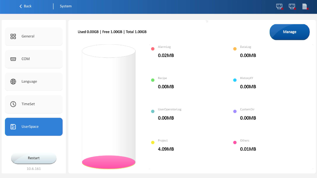
User space
1. Displays total available space, used space and remaining space of user storage. It also shows space occupied by alarm logs, data logs, recipes, historical XY data, operation logs, custom folders, projects and other files. Click the [Manage] button to enter the user storage cleanup page.
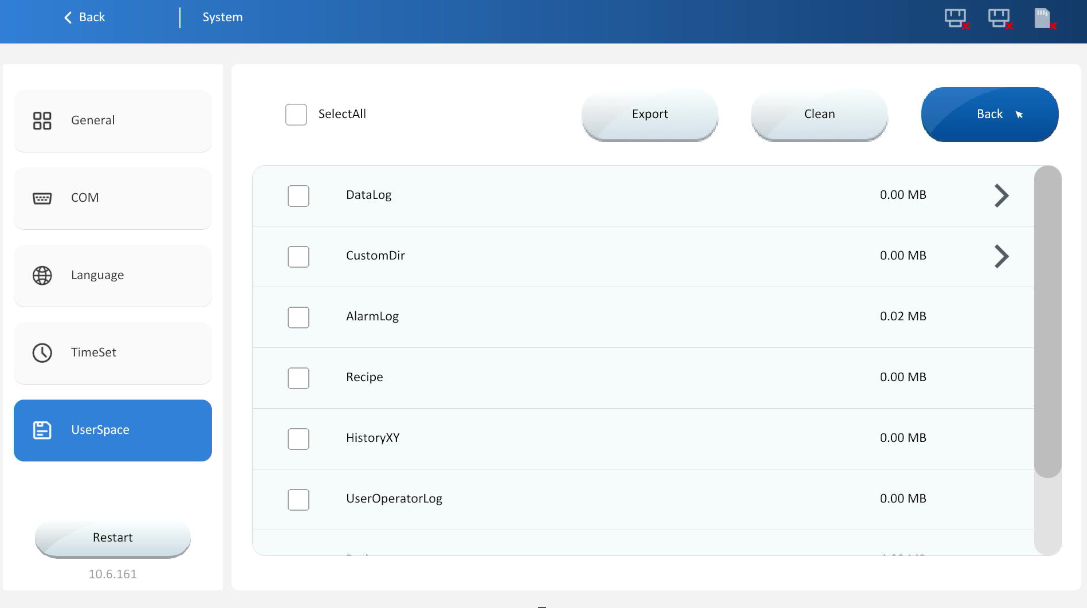
2.On the space cleaning interface, contents including data records, user-defined folders, alarm logs, recipes, historical XY data and user operation records can be cleared or exported. Click Back to return to the user space display interface.
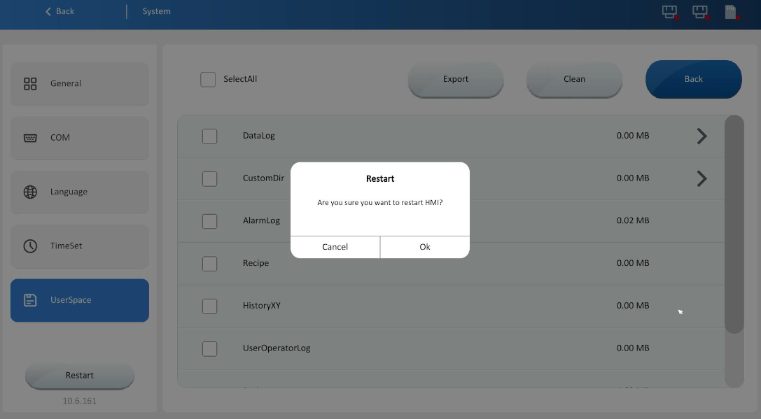
Restart
Click the restart button in the lower left corner to bring up the restart window, then click OK to restart the device, as shown in the image below.
Remote management
[Remote management] ensures the security of remote access and operation. The interface includes remote settings, access verification, device control, ip restriction, and access logs.
Remote HMI configuration interface
(1) Restrict HMI configuration interface access; disable to block remote access.
Default username: HMI configuration interface login account; Default password: 888888
Modify: Click the modify button to change the username and password.
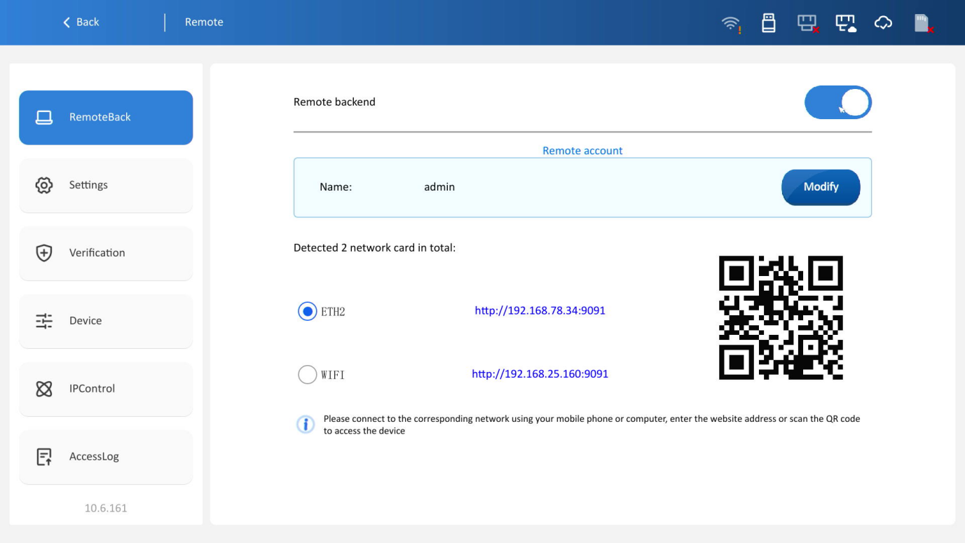
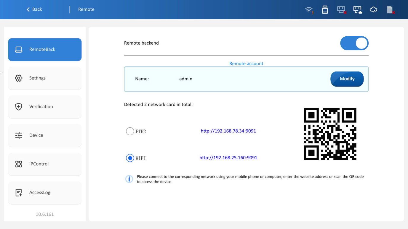
A total of 2 network adapters are detected:
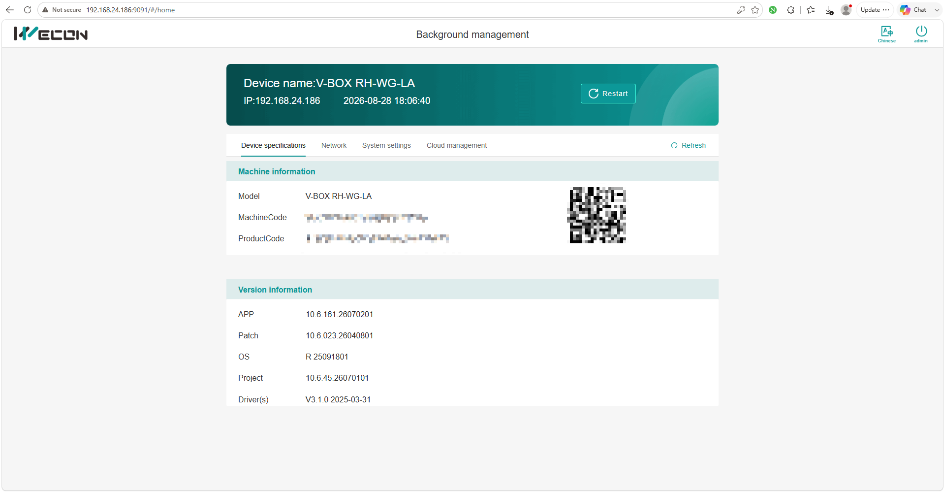
Corresponding access URLs will be displayed after available network adapters are detected. Connection to the same LAN as any adapter via mobile phones, PCs or other terminals, followed by URL input, enables access to the device HMI configuration interface.
QR code quick access is available. Matching QR codes are generated upon selection of different network adapters. Connection to the identical LAN via mobile phones, PCs or other terminals and QR code scanning grant access to the device HMI configuration interface.
Remote settings
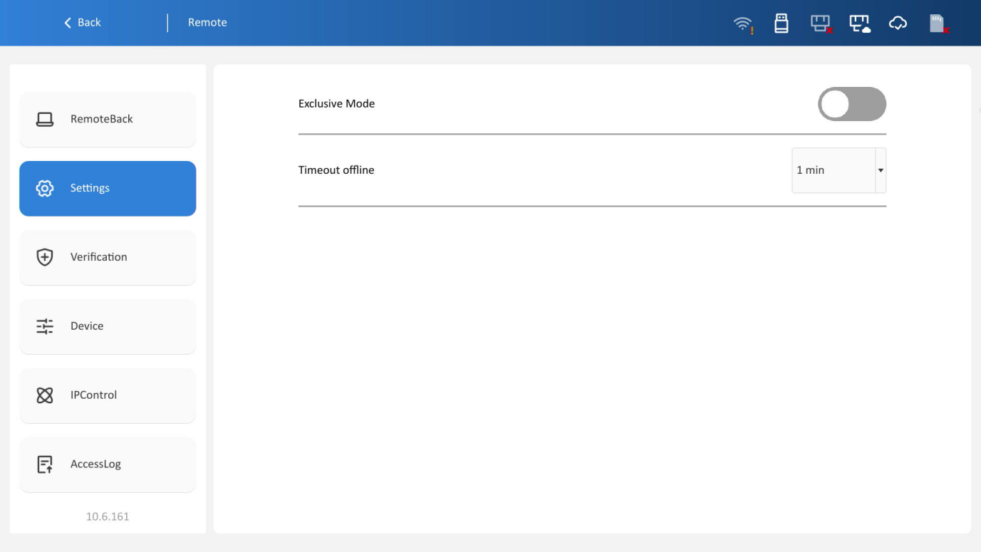
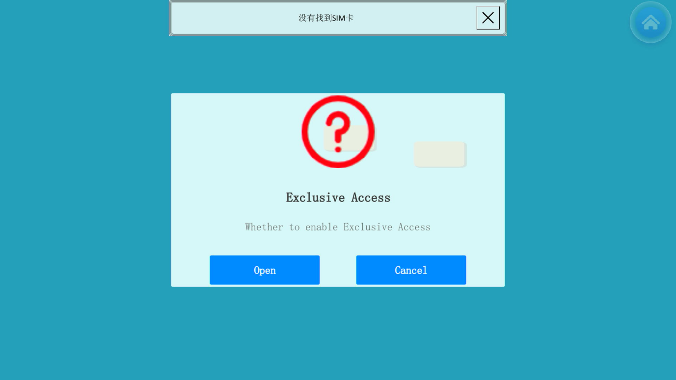
1. Exclusive mode: Once enabled, press and hold a blank area of the device's interface for 10 seconds to enter exclusive mode. In exclusive mode, only one client is allowed to remotely access the device at a time, as shown in the below:
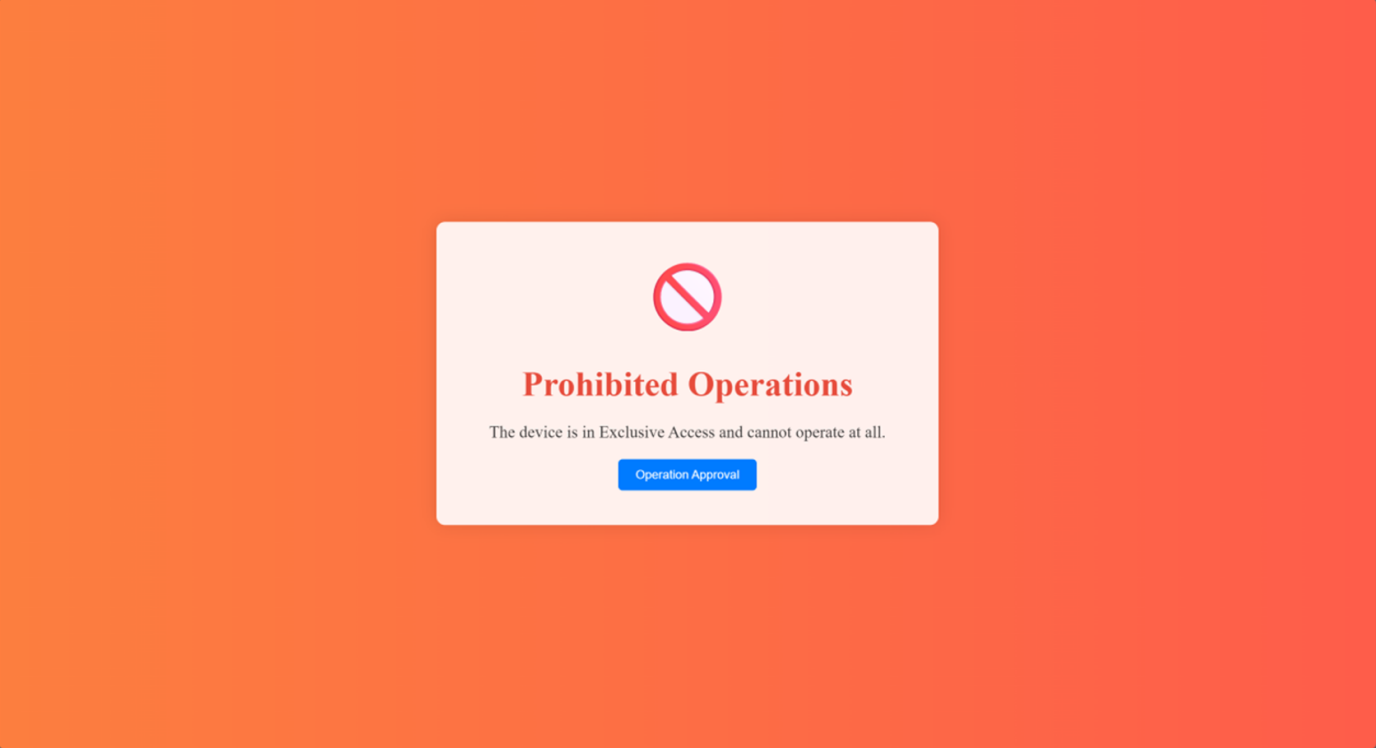
Once enabled, the following interface is displayed on other clients. Access to the device requires a request for authorization.
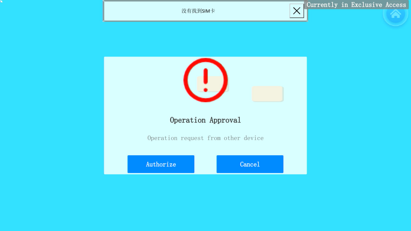
Once a device submits an access request, the currently exclusive occupied device will display the interface below. Click Authorize to transfer exclusive access rights to the requesting device.
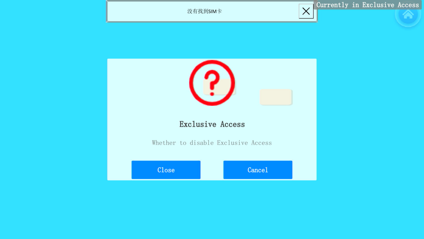
Long press the blank area on the device running interface for 10 seconds again to disable exclusive mode, as shown below:
2. Timeout offline: If no operation is performed on the device for the specified duration, the remote client will be forcibly logged out of access, as shown below:
Access verification
Enabling the access verification function enables access authentication for LAN monitoring and improves its security. A password verification is required to disable the access verification function.
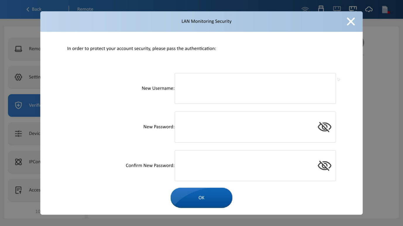
1. Remote account: A username and password must be configured upon initial activation. With these configured, users can securely log in to the LAN monitoring system, as shown in the figure below.
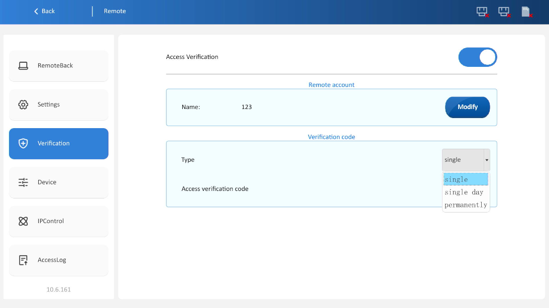
2. Verification code: Users can securely log in to LAN monitoring by entering a verification code. The validity period of the code can be configured by selecting different verification code types.
Users access LAN monitoring via verification codes
Single: Valid for one login only; the code refreshes automatically after a single use.
Daily valid: Valid for one day; auto-refreshes 24 hours after generation.
Long-term: Valid: Long-term: The verification code remains valid indefinitely; it does not automatically refresh.
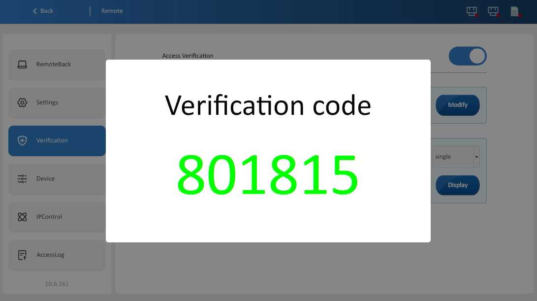
Click [Display] to view the current verification code content, as shown in the figure below.
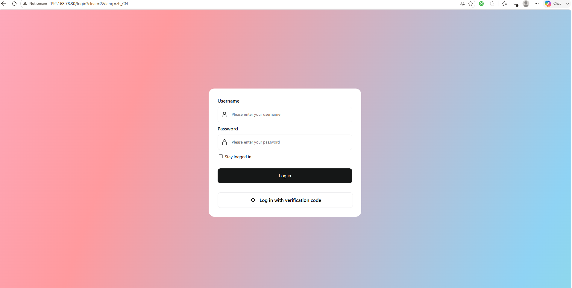
For example, entering the IP address of the device in the browser will jump to the login page, and users can access the device after entering the account password. As shown in the figure:
Device control
✎Note: Clients here refer to browsers, v-net software, device management tools.
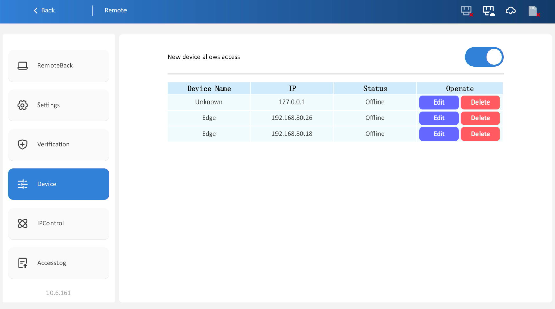
1. New device allows access to buttons: Enabled by default; If this button is turned off, new Clients (Clients that have not previously accessed) are not allowed to access.
2. Display data of accessed devices: Device name, IP address, online status. (online: The device is monitoring access remotely; Offline: Device ends remote monitoring access). The interface is shown in the figure below.
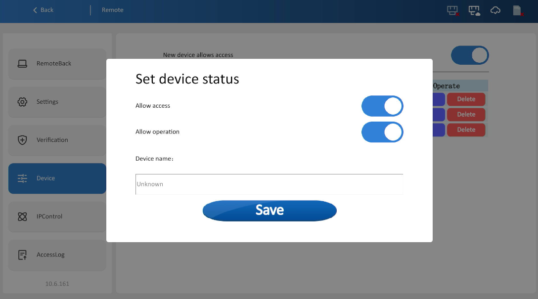
3. Click [Edit] button to pop up device setting window. Modify device access permission, operation permission and device name.
IP restriction
Switch between IP whitelist and blacklist to control client IP access rights.
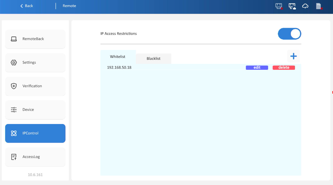
1. Whitelist: Only IPs in the list can access
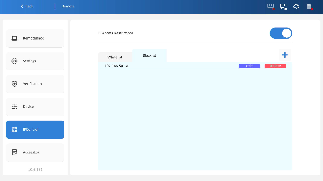
2.Blacklist: IPs in the list are blocked
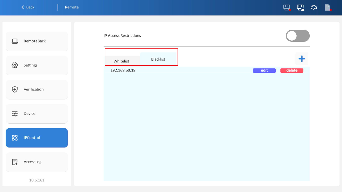
3. The whitelist and blacklist are mutually exclusive; the active mode depends on which window is selected. As shown in the below, the whitelist is currently enabled.
Access logs
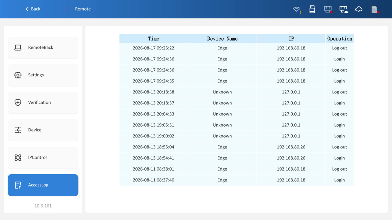
The access log function allows users to view all client operation records, including timestamps, device names, IP addresses, and the operations performed, as shown in the figure below.
Operation definition table
| Operation | Definition |
| Login | Remote monitoring in progress |
| Logout | Exited remote monitoring |
| Password error | Incorrect password during login |
| Verification code error | Incorrect verification code during login |
| IP restricted | When accessing remote monitoring, the following two scenarios
Restricted IP access will be recorded. |
| Device restricted | When accessing remote monitoring, the following two scenarios
|
Upgrade
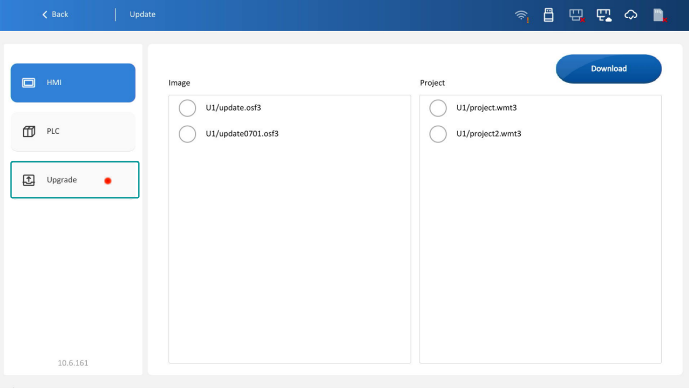
The [Upgrade] interface includes HMI project/image download, PLC download, and online upgrade, as shown in the figure below.
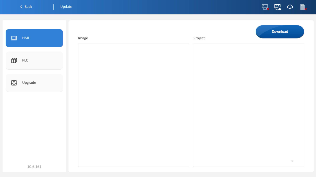
HMI project/image download
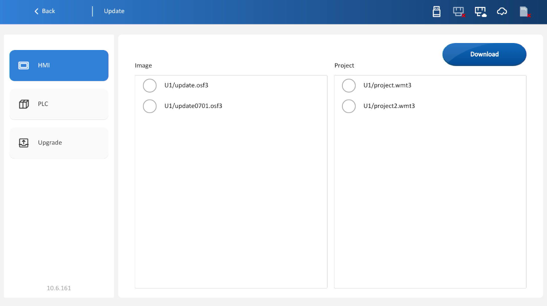
1. Use the USB download tool in PIStudio to create USB upgrade project/image files.

2. Insert the USB drive into the device, select the target file, and clock [Download].
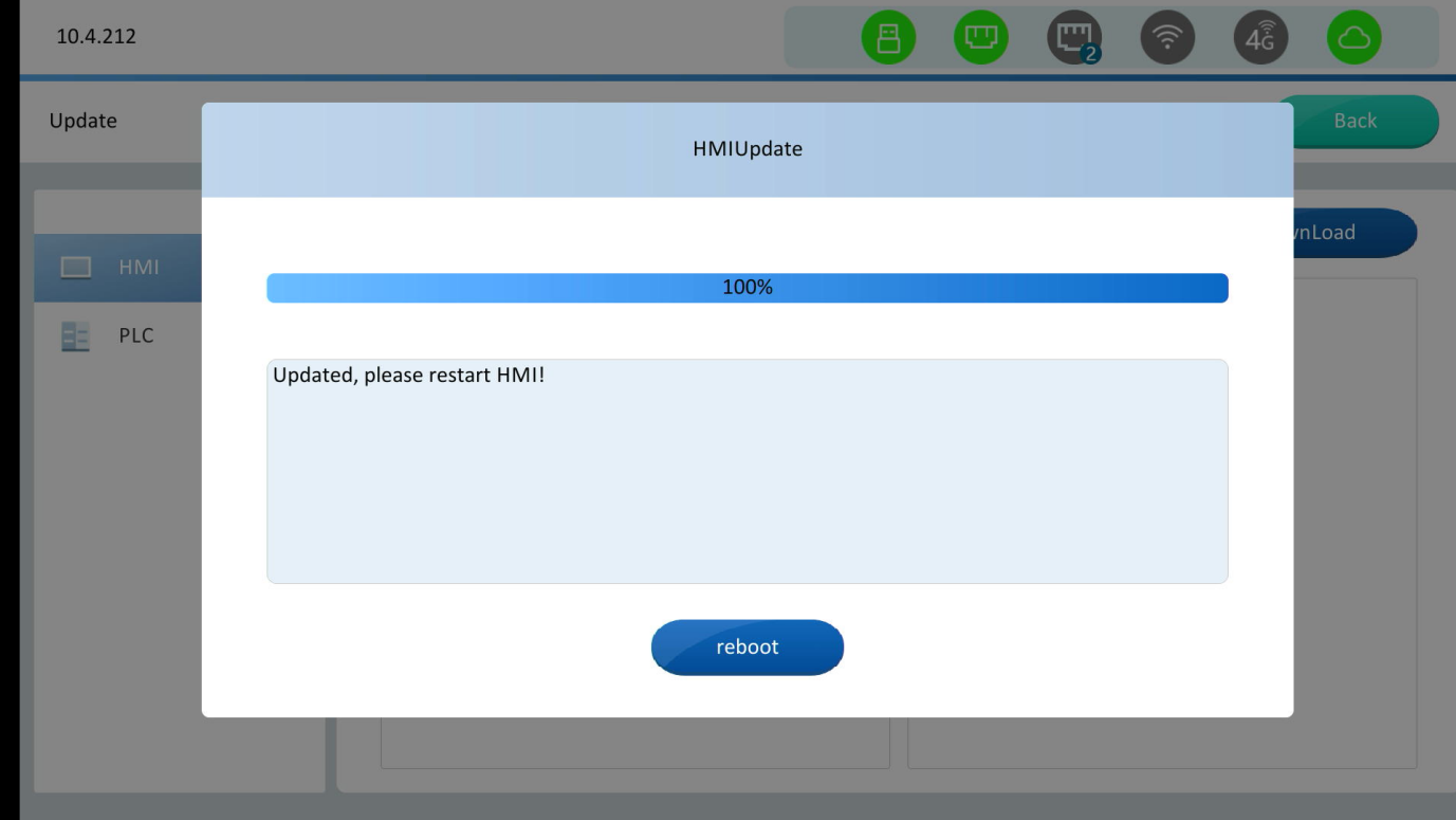
3. Pop-up prompt after download completes. Click [Restart], as shown in the figure below.
PLC program download
Download projects to Wecon 3V/5V/6V series PLCs:
1. Store PLC project files in USB root directory. Insert USB into device to view all project files. Select target file and click [Download].
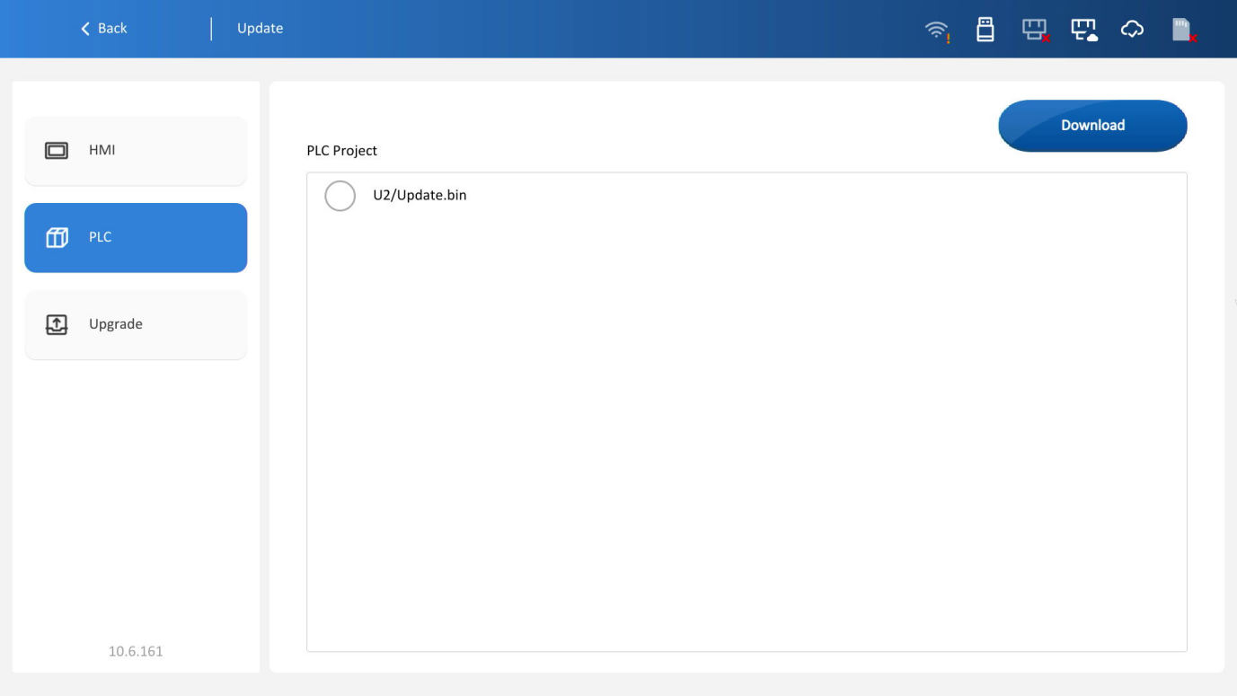
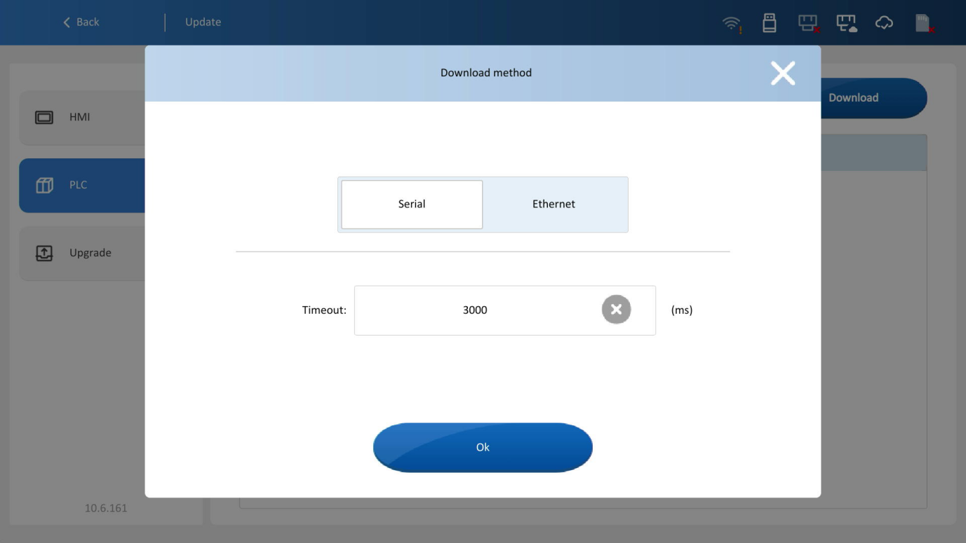
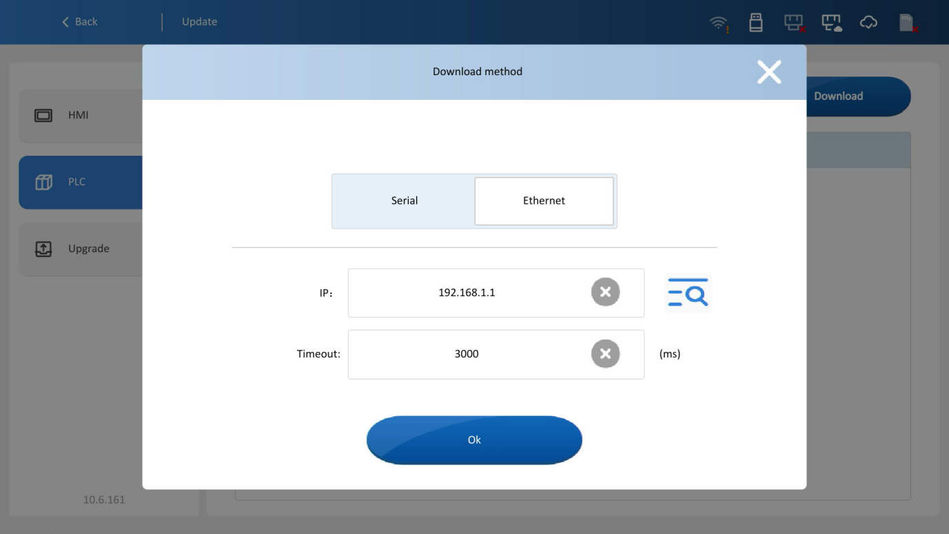
2. Select download mode (Serial/Ethernet) and set timeout (default 3000 ms).
3. For Ethernet download, enter the target PLC’s IP address.
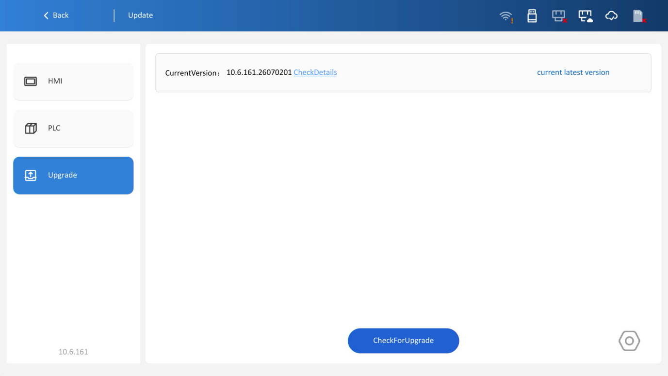
Online upgrade
Upgrade current device firmware online.
1. On the online upgrade page, click the [Check update] button to detect the latest upgradable version. Click the [Setting] button at the bottom right corner to enter the settings page.
If a new version is detected, a button for downloading the latest version will be provided. If the current version is already the latest, a prompt will indicate that you are using the latest version.
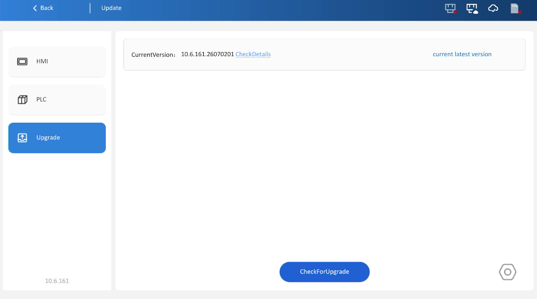
2. When new version detected, click [Download] to get upgrade package.
3. In the settings interface, enable update notifications. A pop-up will appear if the latest online upgrade version is detected; Click [Do not remind for this version] to close the pop-up and no longer receive update notifications for this specific version. Click Cancel to close the window. Click [Update] to jump directly to the HMI configuration online upgrade interface.
When a new version is available, a red dot will indicate this when you enter the background.
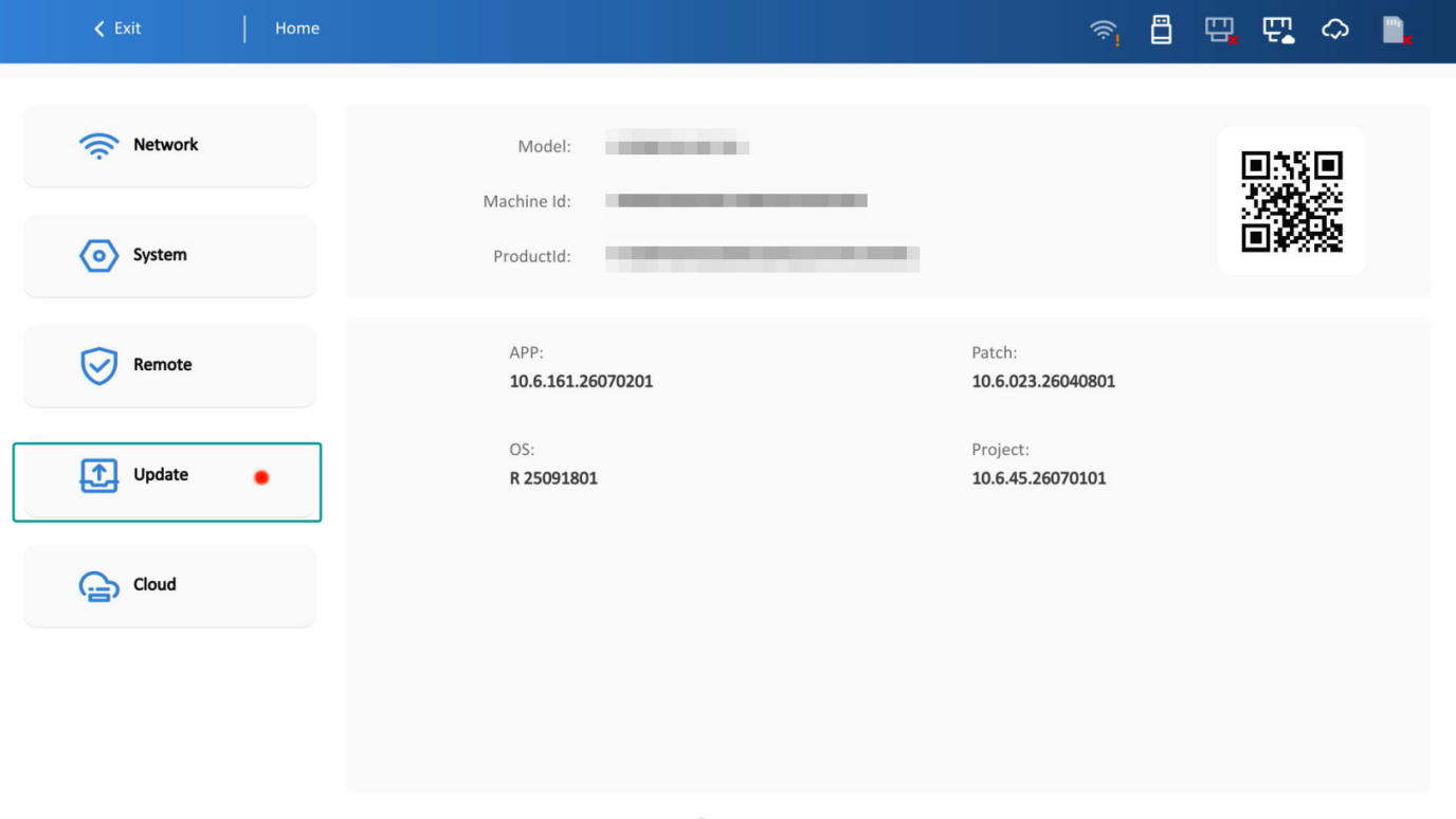
Click [Back] to return to the online upgrade interface
Cloud management
The [Cloud management] interface includes Basic Settings, IoT Card, and multi-machine interconnection.
Basic settings
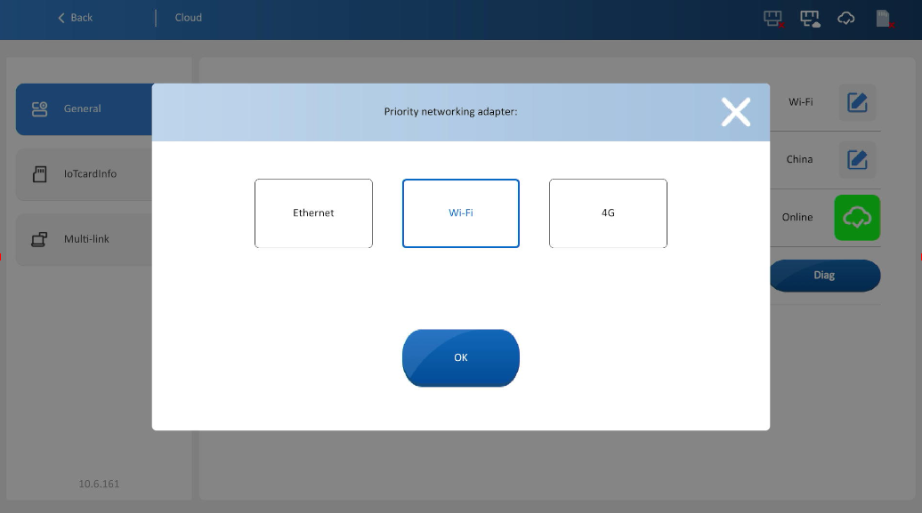
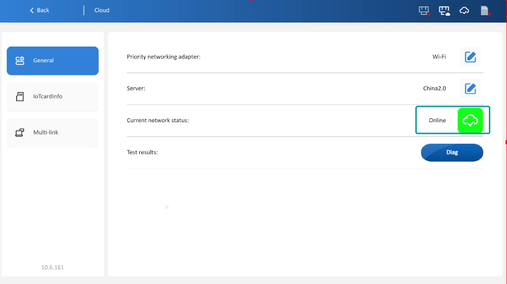
1. The basic settings for cloud management include: Preferred cloud network card, server, current status, and diagnostic results.
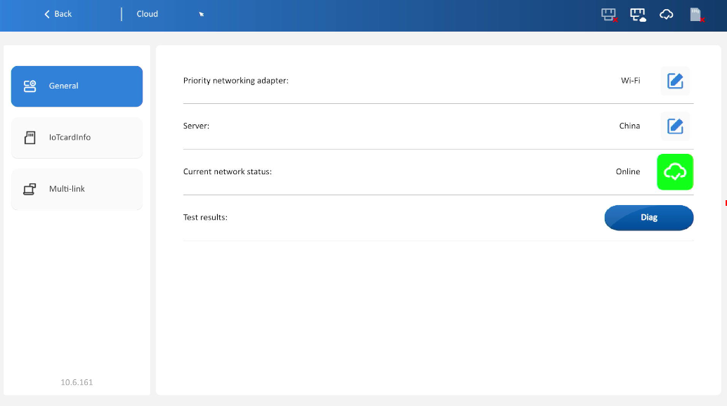
2. Preferred cloud network card: Select the network for cloud service, as shown in the figure below.
3. Server: Select the cloud server, as shown in the figure below.
Note: Select the corresponding 2.0 server for V-Net2.0
4. Current Status: Displays cloud connection status, as shown in the figure below.
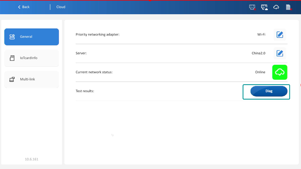
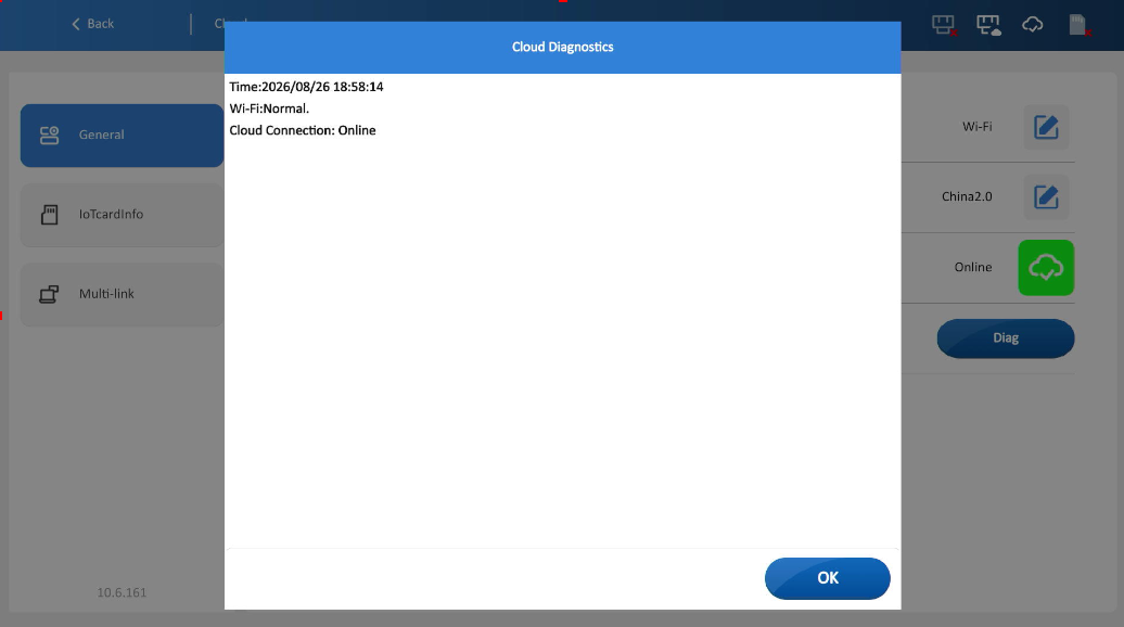
5. Diagnosis result: Display diagnostic results for Ethernet, Wi-Fi, 4G and cloud connection.
IoT card
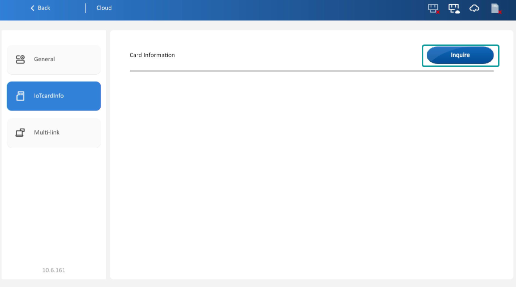
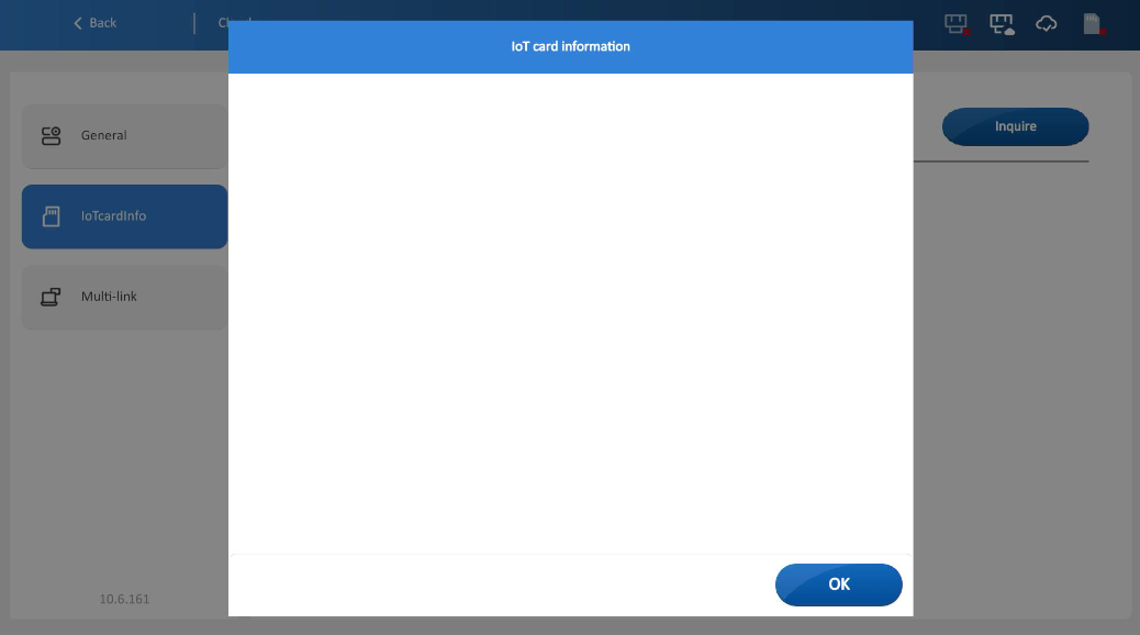
Click [Query] to view Wecon IoT card information. Only Wecon official IoT cards supported.
Multi-link
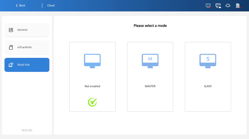
Multi-link adopts master-slave communication mode and uses Ethernet cables to realize enable one HMI project to display its interface on multiple screens. One HMI connects another HMI via Ethernet port to read or write PLC data connected to the master. In multi-machine interconnection, one HMI is the master and others are slaves. Only the master HMI can communicate with PLC and receive PLC data. The master transmits the received data to all slaves.
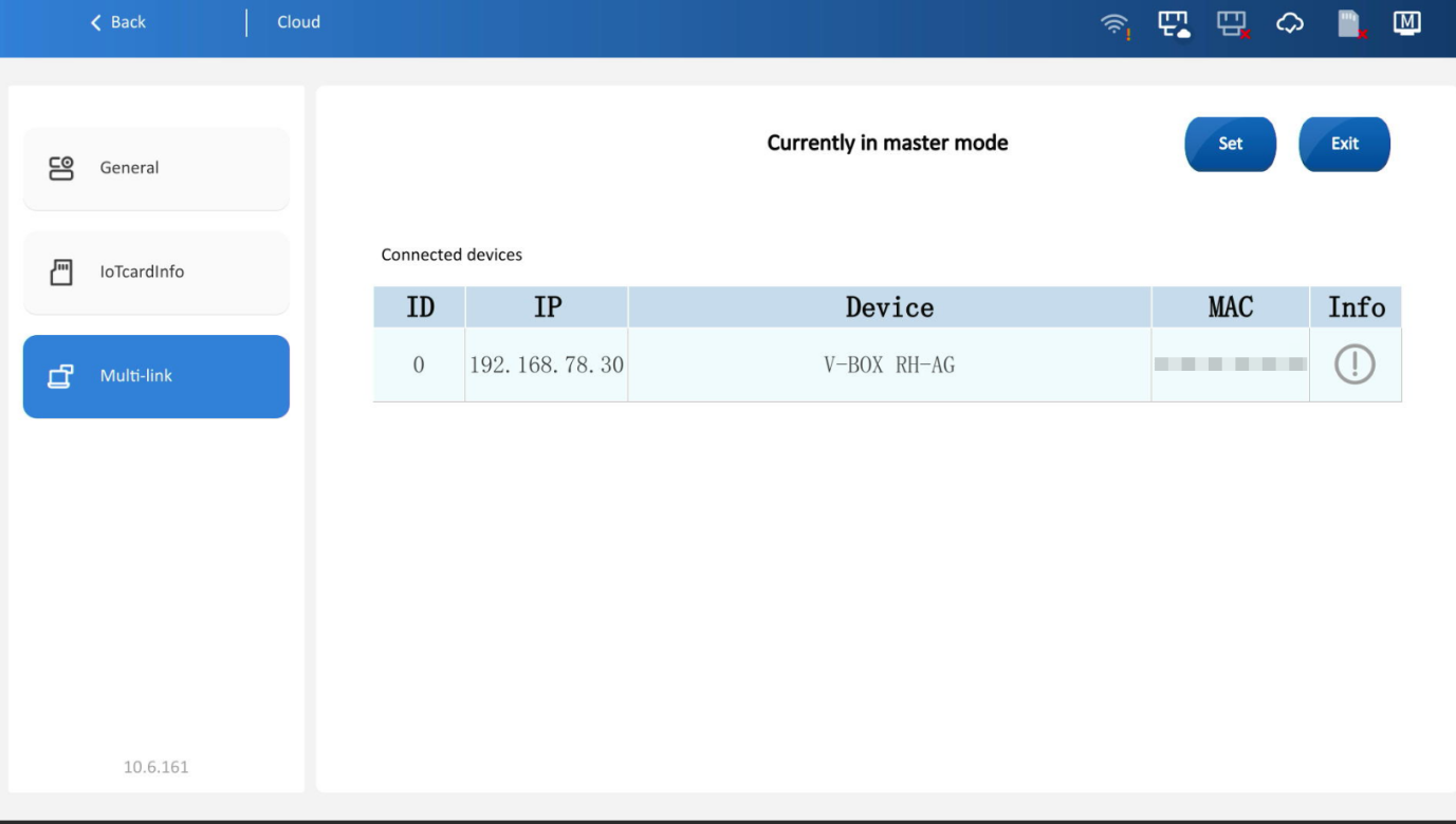
1.Master mode: Select master mode, and the slave can connect to the machine, as shown in the figure:
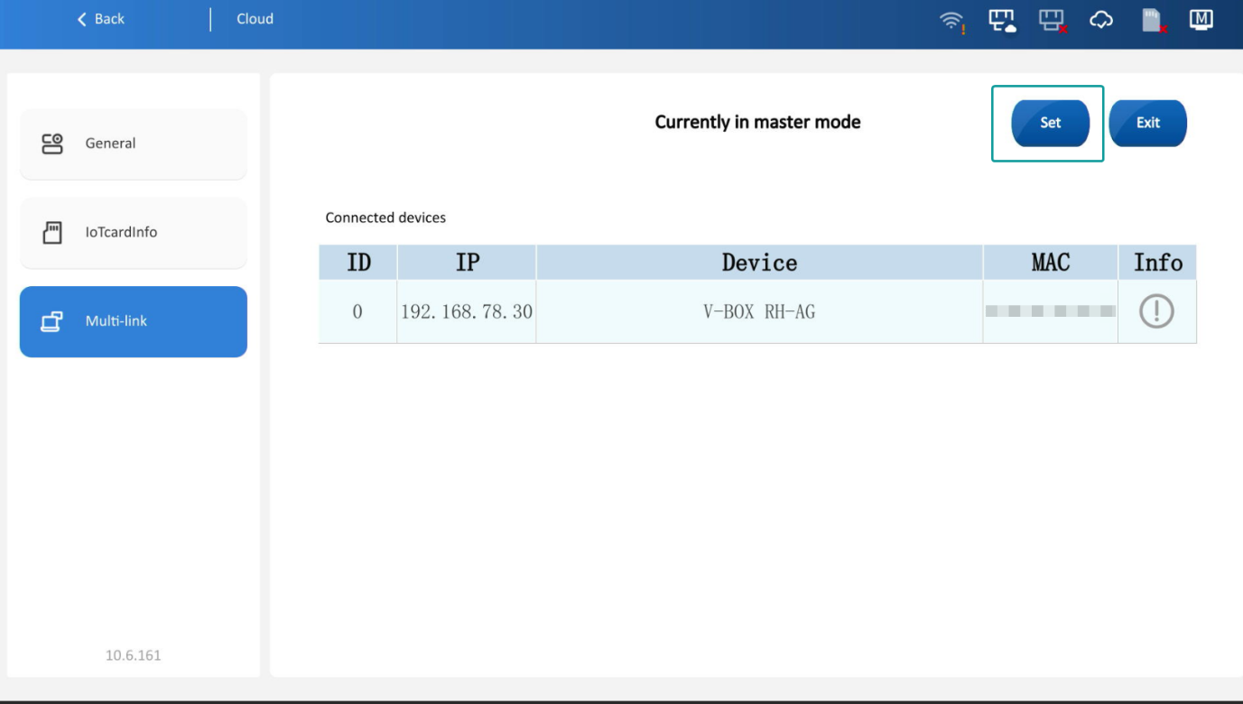
Click [Settings] to set connection passwords, customize device names, configure groups and set startup screens for each group.
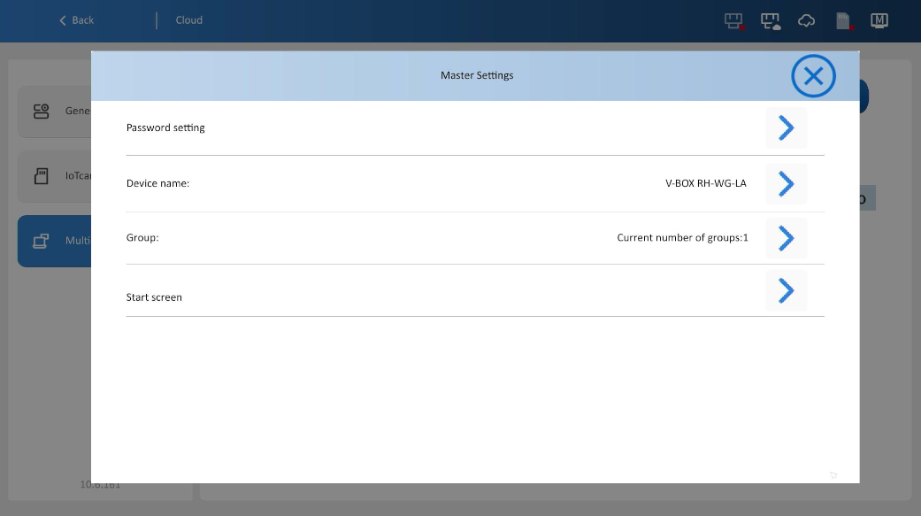
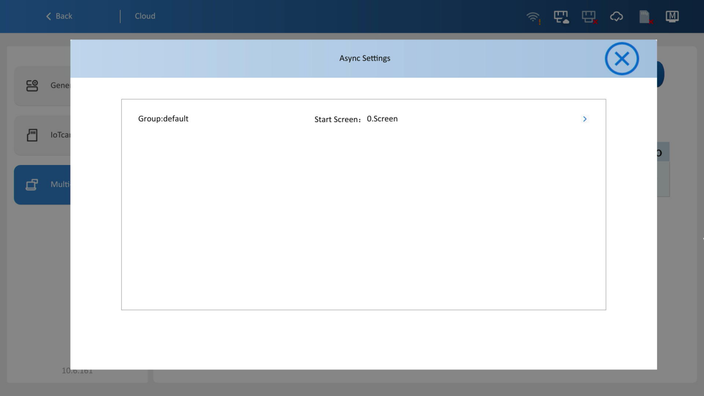
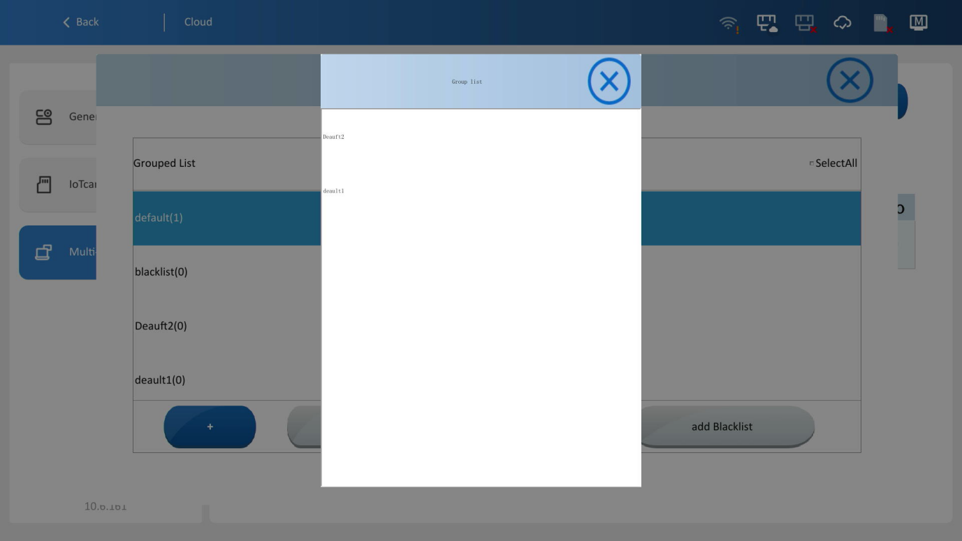
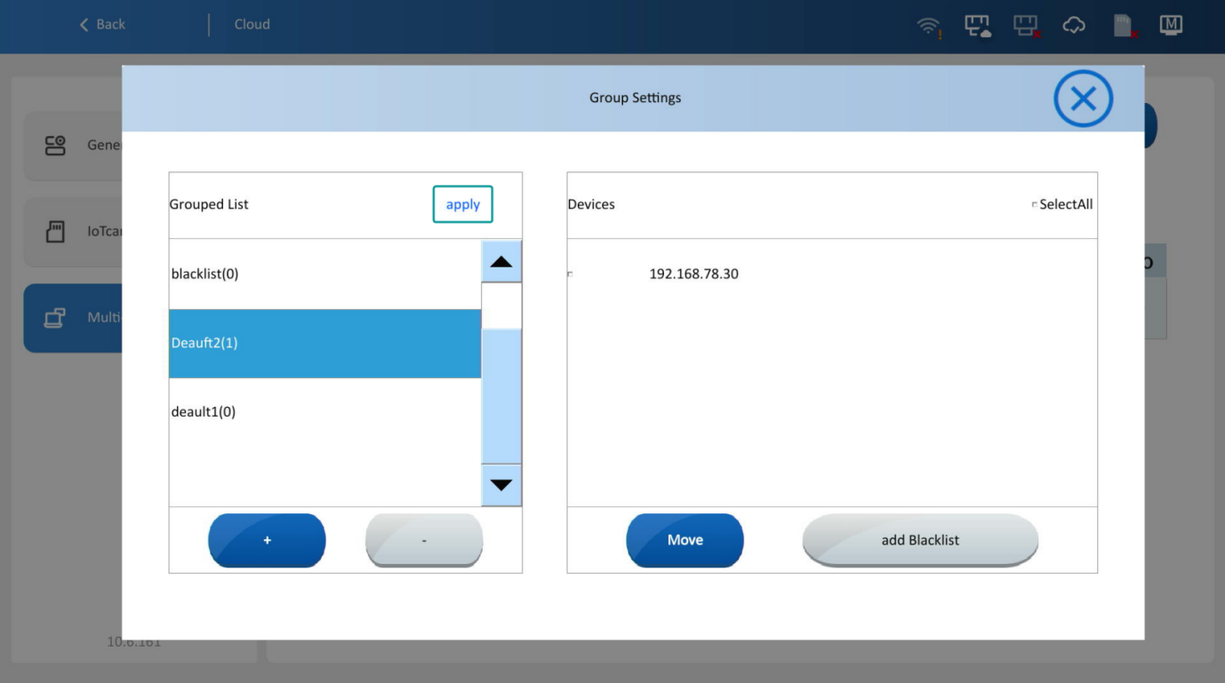
Group function: Devices are assigned to groups based on the different screens. Devices in the same group display the same screen (synchronized); Devices in different groups may display different screens (asynchronous). Devices in the default group share the same startup screen as the master. Other groups support configuration of different startup screens.
If a slave device is not assigned to any group, it will be automatically assigned to the default group and the screen be synchronized with the master. If it is assigned to a specific group, the screen will be asynchronous with the host (when the master switches screens, the slave will not switch).
For example:
Groups: Default group, the screen is synchronized with the host, and the startup screen cannot be modified.
Groups: Group one, the startup screen can be configured. The startup screen configured in the figure is circular chart.
Groups: Group two, the startup screen can be configured. The startup screen configured in the figure is XY chart.
When one device in any group switches screens, all devices in the same group will switch screens simultaneously, while the screens of other groups will remain unchanged.
If any device in any group switches its screen, all devices in the same group will switch screens together, while the screens of the remaining groups remain unchange
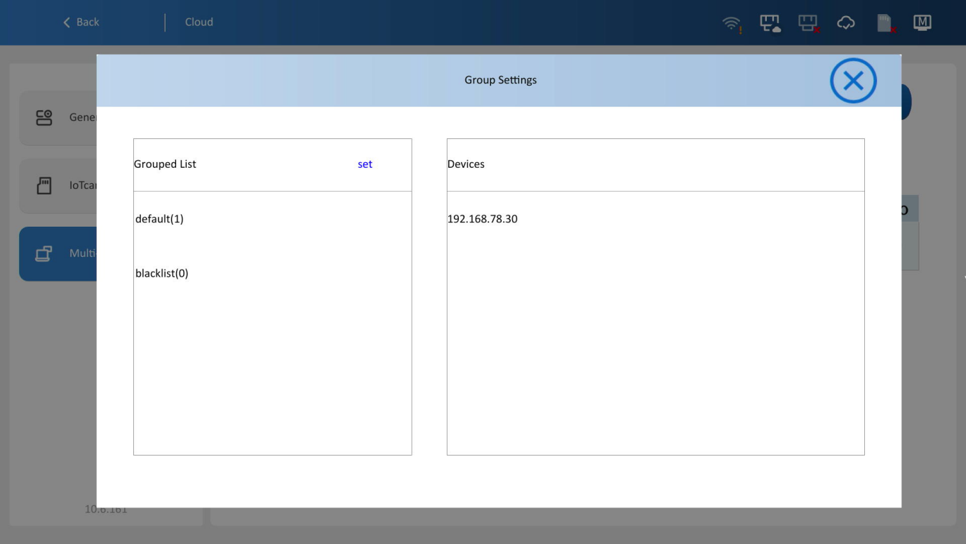
All unassigne slaves are in the default group.
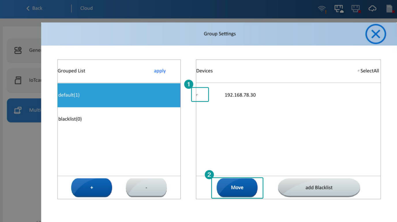
In the left list, select the original group. In the right list, select the device. Click "Move", then click "Group Two" to move the device to Group Two. Click "Apply" to complete the grouping. After that, the device (192.168.50.18) will be in Group Two, and its screen switching will no longer be affected by the host.
(If a slave device is added to the blacklist, it will be unable to connect to the host.)
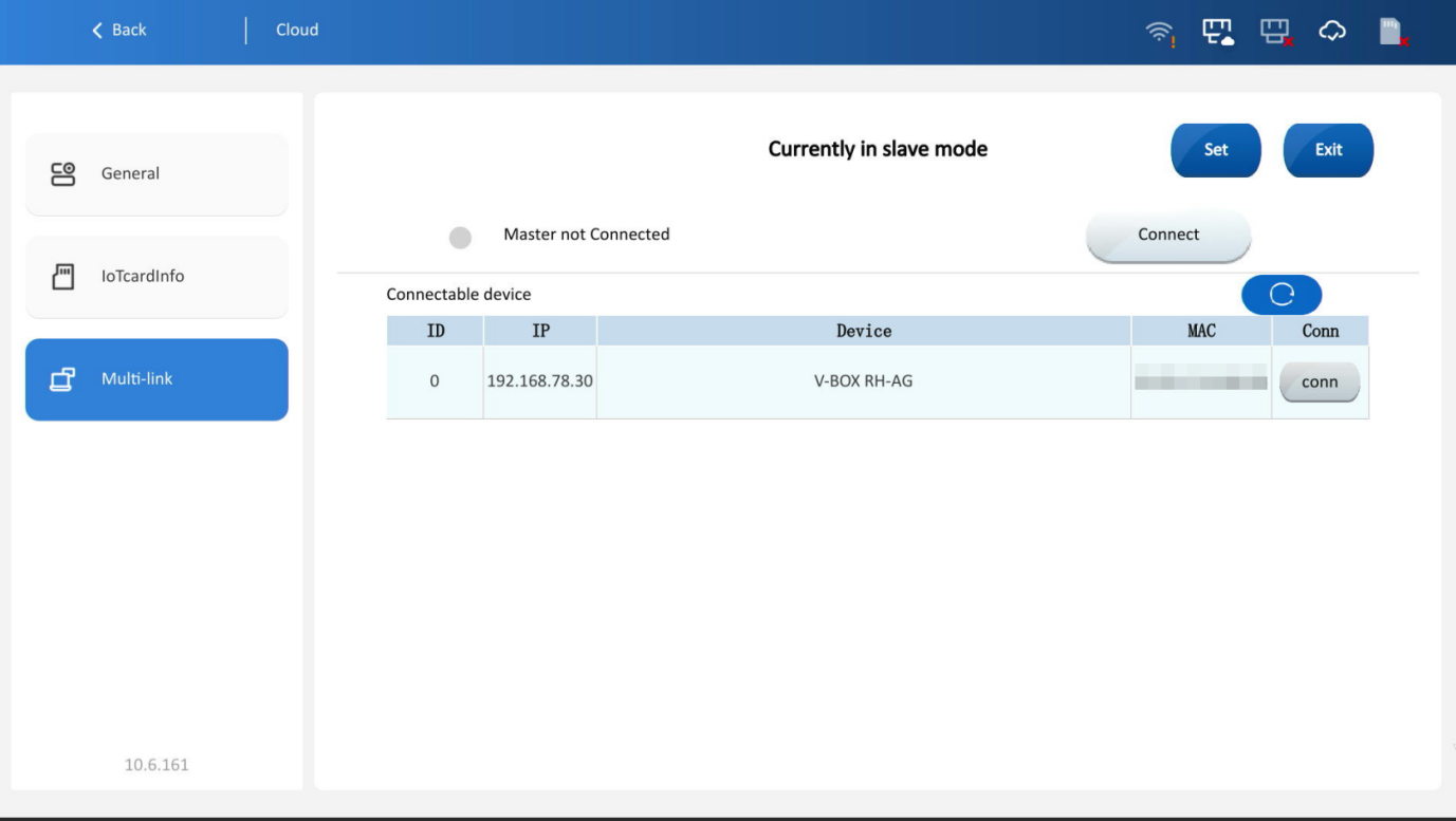
2. Slave mode: Switch to Slave Mode, search the device list, select the target master device, and click [Connect]. If the master requires a password, enter it and click OK.
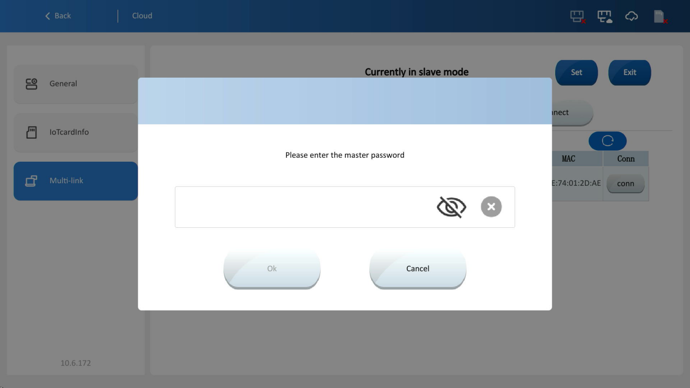
After successful connection, the device will automatically restart.. If the project displayed at startup matches that of the master, it indicates a successful connection.
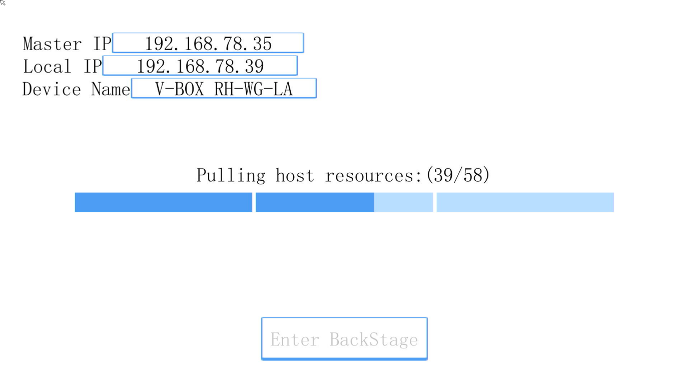
3. Screens with different sizes cannot connect to each other. Different screen mirroring versions also cannot be interconnected.