Schneider Modicon MODBUS RTU
HMI Setting
| Parameters | Recommended | Notes |
|---|---|---|
| Protocol | Schneider MODBUS RTU | |
| Connection | RS485 | |
| Baud rate | 19200 | |
| Data bit | 8 | |
| Parity | Even | |
| Stop bit | 1 | |
| PLC station No. | 1 |
PLC Setting
| Communication mode | Modbus RTU protocol |
|---|
Device Address
| Bit/Word | Device type | Format | Range | Memo |
|---|---|---|---|---|
| B | IX | DDDDDo | 0 ~ 655357 | Input bit (read only) |
| B | QX | DDDDDo | 0 ~ 655357 | Write multiple coils |
| B | MX | DDDDDDo | 0 ~ 9999997 | Output register bit (octal) |
| W | MW | DDDDDD | 0 ~ 999999 | Output register |
| DW | MD | DDDDDD | 0 ~ 999999 | Output register |
Wiring Diagram
RS-485 2W (RJ45 Connector): The following is the view from the soldering point of a connector.

TM218 Series
HMI Setting
| Parameters | Recommended | Notes |
|---|---|---|
| Protocol | Schneider Modicon MODBUS RTU | |
| Connection | RS485 | |
| Baud rate | 19200 | |
| Data bit | 8 | |
| Parity | Even | |
| Stop bit | 1 | |
| PLC station No. | 1 |
Device Address
| Bit/Word | Device type | Format | Range |
|---|---|---|---|
| B | IX | IX dddd.d | 0 to 65535 |
| B | QX | QX dddd.d | 0 to 65535 |
| B | MX | MX dddd.dd | 0 to 999999 |
| W | MW | MW dddd | 0 to 999999 |
Configure the communication protocol


PLC Setting:
Open SoMachine Central, create a new project or open the project that has been created.
Create new project: [Create a new project]→[Empty Project]→[OK]→[Open Configuration]


Into the [Open Configuration].
[Untitled]→[Add Device]→[Logic Controller]→[M218]→[TM218LDA16DRN]

PLC Default Parameters:
In the Devices tree [MyController]→[Serial Line 2]→[Modbus_Manager]
Modbus:
[Transmission Mode] RTU→[Addressing] Slave
Serial Line Settings:
[Baud rate] 19200, [Data bits] 8, [Stop bits] 1, [Parity] EVEN, [Physical Medium] RS485

Cable Wiring

Schneider TM221 Ethernet
Supported Series: Modicon M221 Series
HMI Setting
| Items | Settings | Note |
| Protocol | Schneider TM221 | |
| Connection | Ethernet | |
| Port No. | 502 | |
| Device No. | 1 | |
| HMI No. | 0 |
Address List
| Type | Address Type | Format | Range | Note |
|---|---|---|---|---|
| Bit | IWMB | IWMB DD.dd | 0~20.15 | Output Register(Bit type) |
| QWMB | QWMB DD.dd | 0~20.15 | Input Register(Bit type) | |
| MWB | MWB DDDD.dd | 0~8000.15 | Internal memory word(Bit type) | |
| M | M DDDD | 0~1024 | Internal memory bit | |
| IWB | IWB DDDDDD.dd | 0~255255.15 | Analog Input(Bit type) | |
| I | I DDD.dd | 0~255.13 | Digital Input | |
| Q | Q DDD.d | 0~255.9 | Digital Output | |
| S | S DDD | 0~159 | System Bit | |
| Word | IWM | IWM DD | 0~20 | Output Register |
| QWM | QWM DD | 0~20 | Input Register | |
| MW | MW DDDD | 0~7999 | Internal memory word | |
| MD | MD DDDD | 0~7998 | Internal memory double word | |
| MF | MF DDDD | 0~7998 | Internal memory floating point | |
| IW | IW DDDDDD | 0~255255 | Analog Input | |
| SW | SW DDD | 0~233 | System word | |
| KW | KW DDD | 0~511 | Constant word | |
| KD | KD DDD | 0~510 | Internal constant double word | |
| KF | KF DDD | 0~510 | Internal constant floating point | |
| TM_V | TM_V DDD | 0~254 | Timer | |
| TM_P | TM_P DDD | 0~254 | Timer |
PLC Settings
1.Open the software EcoStruxure Machine Expert - Basic, drag the corresponding model from M221 Logic Controller list into the [Configuration] tab.
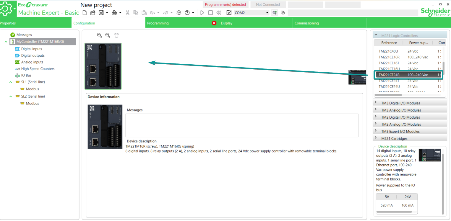
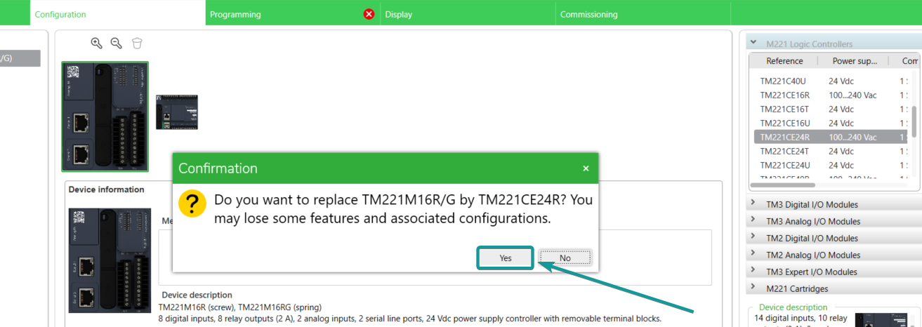
2.Click [Yes] to replace the model in current project.
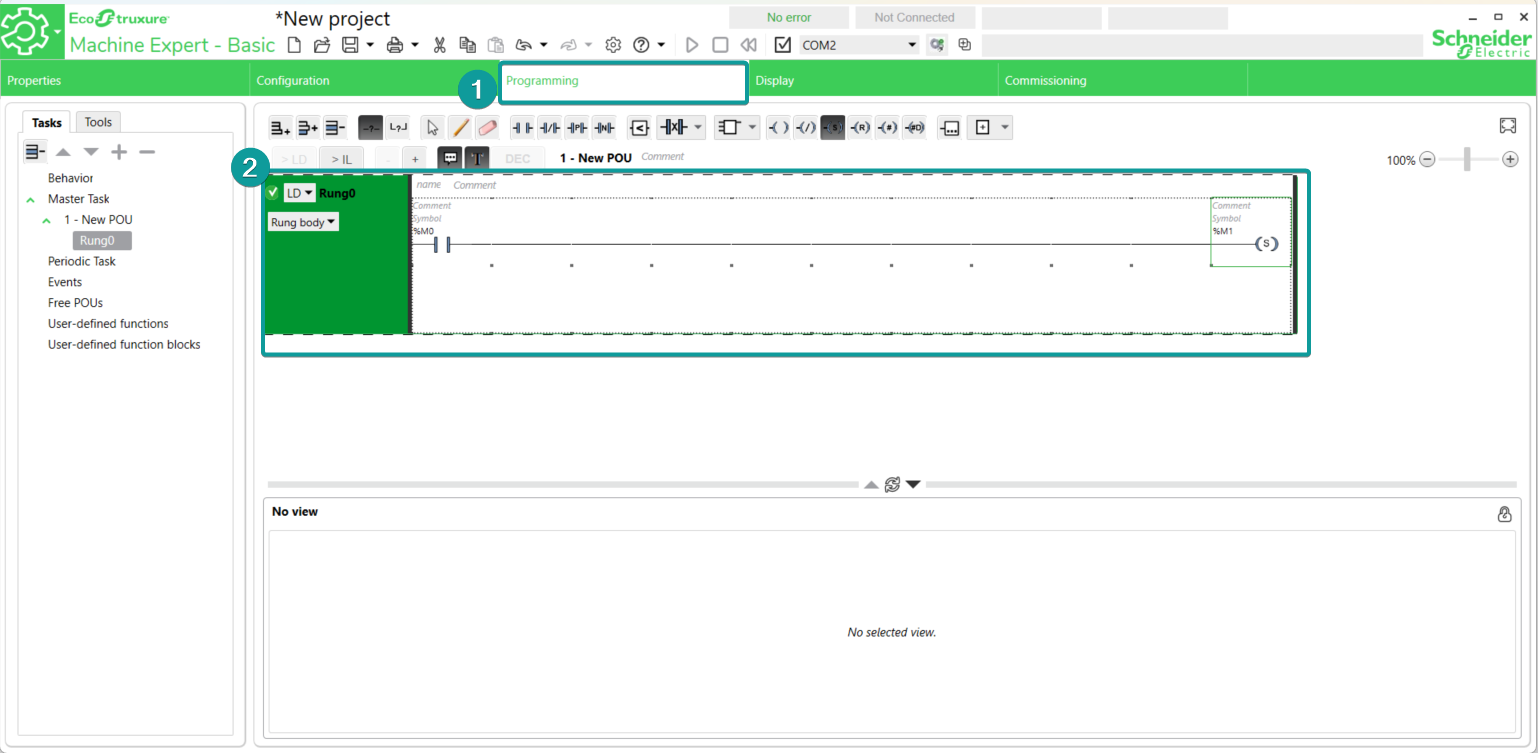
3.Program the PLC project in [Programming] tab.
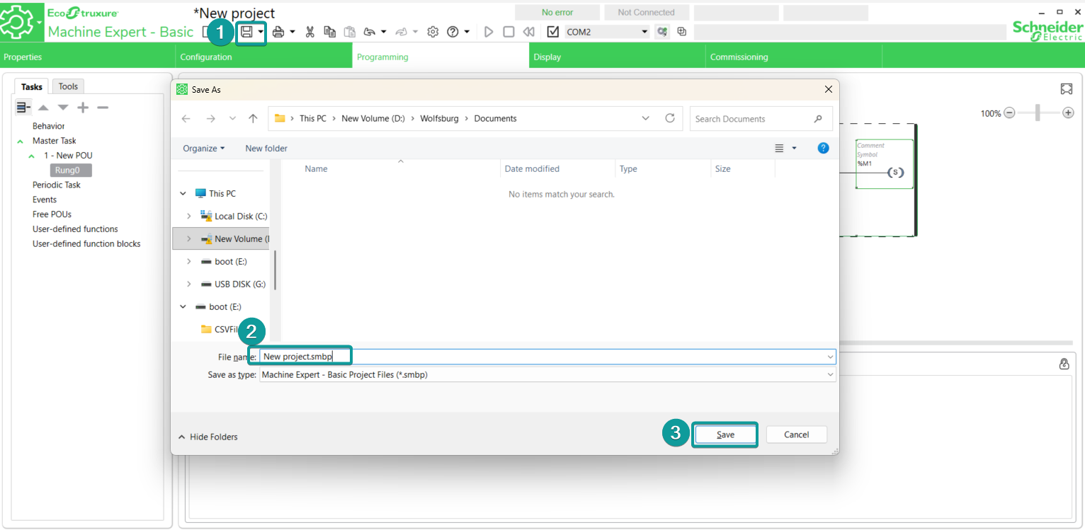
4. Click [Save] to save the project file.
5. Go to the Commissioning tab to login the PLC