04 Logic operation
NEG/16-bit complement
NEG(P)
After inverting the sign of the BIN 16-bit device specified in (D), store it in the device specified in (D).
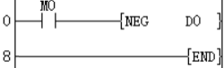
-[NEG (D)]
Content, range and data type
| Parameter | Content | Range | Data type | Data type (label) |
| (D) | The start device that stores the data complement of 2 | -32768 to 32767 | Signed BIN16 | ANY16_S |
Device used
| Instruction | Parameter | Devices | Offset modification | Pulse extension | ||||||||
| KnX | KnY | KnM | KnS | T | C | D | R | SD | [D] | XXP | ||
| NEG | Parameter 1 | ● | ● | ● | ● | ● | ● | ● | ● | ● | ● | ● |
Features
• Invert the sign of the BIN 16-bit device specified in (D), and store it in the device specified in (D).
• Used when inverting positive and negative signs.
Error code
| Error code | Content |
| 4085H | The output results of (D) in the read application instruction exceed the device range |
| 4086H | The output result of (D) in the write application instruction exceeds the device range |
Example
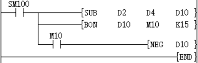
In the two examples below, if D2=K4 and D4=K8, or D2=K8 and D10 is always K4.
Each time M0 is set, the device value specified in D0 is reversed.
Take the absolute value of the difference of the subtraction operation.
If D2>D4, M10=On. If D2=D4, M11=On. If D2 <D4, M12=On. This ensures that D10 is positive.
It can also be represented by the following program:
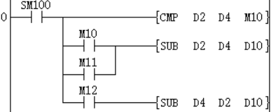
When bit15 of D10 is "1" (indicating that D10 is a negative number), M10 = On, use NEG instruction to complement D10 to obtain the absolute value of D10.
In the above two examples, if D2=K4, D4=K8; or D2=K8, D4=K4, the result of D10 is K4.
DNEG/32-bit complement
DNEG(P)
After inverting the sign of the BIN 32-bit device specified in (D), store it in the device specified in (D).
-[DNEG (D)]
Content, range and data type
| Parameter | Content | Range | Data type | Data type (label) |
| (D) | The start device that stores the data complement of 2 | -2147483648 to 2147483647 | Signed BIN16 | ANY16_S |
Device used
| Instruction | Parameter | Devices | Offset modification | Pulse extension | ||||||||||
| KnX | KnY | KnM | KnS | T | C | D | R | SD | LC | HSC | [D] | XXP | ||
| DNEG | Parameter 1 | ● | ● | ● | ● | ● | ● | ● | ● | ● | ● | ● | ● | ● |
Features
• Invert the sign of the BIN 32-bit device specified in (D) and store it in the device specified in (D).
• Used when inverting positive and negative signs.
Error code
| Error code | Content |
| 4085H | The output results of (D) in the read application instruction exceed the device range |
| 4086H | The output result of (D) in the write application instruction exceeds the device range |
Example
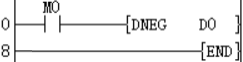
Each time M0 is set, the device value specified in (D1, D0) is reversed.
WOR/16-bit data logical OR
WOR(P)
Perform a logical OR operation on the BIN 16-bit data of the device specified in (S1) and the BIN 16-bit data of the device specified in (S2), and store the result in the device specified in (D).
-[WOR (S1) (S2) (D)]
Content, range and data type
| Parameter | Content | Range | Data type | Data type (label) |
| (S1) | Stores data for logical OR operation or a device that stores data | -32768 to 32767 | Signed BIN16 | ANY16_S |
| (S2) | Stores data for logical OR operation or a device that stores data | -32768to 32767 | Signed BIN16 | ANY16_S |
| (D) | Device for storing logic or result | Signed BIN16 | ANY16_S |
Device used
| Instruction | Parameter | Devices | Offset modification | Pulse extension | ||||||||||
| KnX | KnY | KnM | KnS | T | C | D | R | SD | K | H | [D] | XXP | ||
| WOR | Parameter 1 | ● | ● | ● | ● | ● | ● | ● | ● | ● | ● | ● | ● | ● |
| Parameter 2 | ● | ● | ● | ● | ● | ● | ● | ● | ● | ● | ● | ● | ● | |
| Parameter 3 | ● | ● | ● | ● | ● | ● | ● | ● | ● | ● | ||||
Features
• Perform a logical OR operation on the BIN 16-bit data of the device specified in (S1) and the BIN 16-bit data of the device specified in (S2), and store the result in the device specified in (D).
In the case of bit devices, bit devices after the number of points specified by the number of digits will be calculated as 0.
Error code
| Error code | Content |
| 4085H | The output results of (S1) and (S2) in the read application instruction exceed the device range |
| 4086H | The output result of (D) in the write application instruction exceeds the device range |
Example
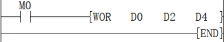
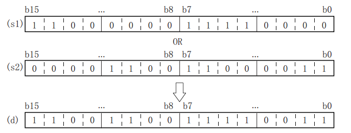
When M0 is set, (D0) and (D2) are logically performed, and the value is stored in (D4), that is (D0)∨(D2) → (D4)
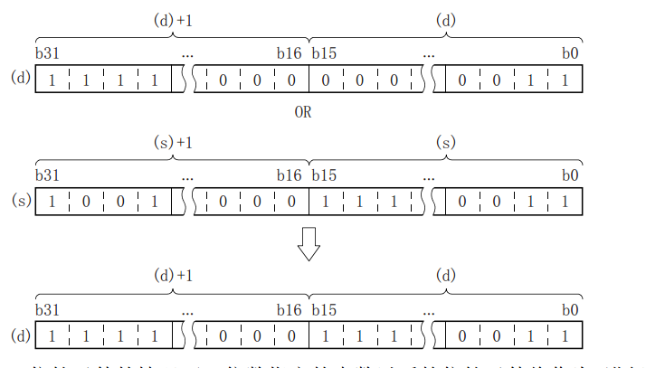
DOR/32-bit data logical OR
DOR(P)
After inverting the sign of the BIN 32-bit device specified in (D), store it in the device specified in (D).
-[DOR (S1) (S2) (D)]
Content, range and data type
| Parameter | Content | Range | Data type | Data type (label) |
| (S1) | Stores data for logical OR operation or a device that stores data | -2147483648 to 2147483647 | Signed BIN32 | ANY32_S |
| (S2) | Stores data for logical OR operation or a device that stores data | -2147483648 to 2147483647 | Signed BIN32 | ANY32_S |
| (D) | Device for storing logic or result | Signed BIN32 | ANY32_S |
Device used
| Instruction | Parameter | Devices | Offset modification | Pulse extension | ||||||||||||
| KnX | KnY | KnM | KnS | T | C | D | R | SD | LC | HSC | K | H | [D] | XXP | ||
| DOR | Parameter 1 | ● | ● | ● | ● | ● | ● | ● | ● | ● | ● | ● | ● | ● | ● | ● |
| Parameter 2 | ● | ● | ● | ● | ● | ● | ● | ● | ● | ● | ● | ● | ● | ● | ● | |
| Parameter 3 | ● | ● | ● | ● | ● | ● | ● | ● | ● | ● | ● | ● | ||||
Features
Perform a logical OR operation on the BIN 32-bit data of the device specified in (S1) and the BIN 32-bit data of the device specified in (S2), and store the result in the device specified in (D).
In the case of bit devices, bit devices after the number of points specified by the number of digits will be calculated as 0.
Error code
| Error code | Content |
| 4085H | The output results of (S1) and (S2) in the read application instruction exceed the device range |
| 4086H | The output result of (D) in the write application instruction exceeds the device range |
Example
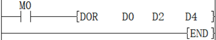
When M0 is set, (D1, D0) and (D3, D2) are logically performed, and the value is stored in (D5, D4), that is, (D1, D0)∨(D3, D2) → (D5, D4) ).
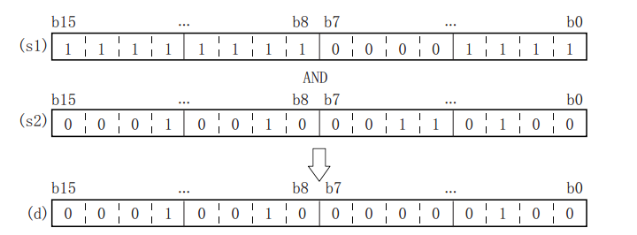
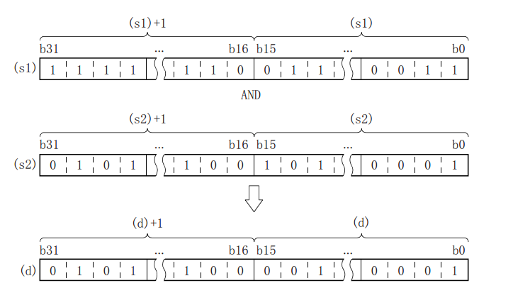
WAND/16-bit data logic AND
WAND(P)
Perform a logical AND operation on each bit of the BIN 16-bit data of the device specified in (S1) and the BIN 16-bit data of the device specified in (S2), and store the result in the device specified in (D).
-[WAND (S1) (S2) (D)]
Content, range and data type
| Parameter | Content | Range | Data type | Data type (label) |
| (S1) | Store the data for logical AND operation or the device storing the data | -32768to 32767 | Signed BIN16 | ANY16_S |
| (S2) | Store the data for logical AND operation or the device storing the data | -32768 to 32767 | Signed BIN16 | ANY16_S |
| (D) | Device for storing logic and result | Signed BIN16 | ANY16_S |
Device used
| Instruction | Parameter | Devices | Offset modification | Pulse extension | ||||||||||
| KnX | KnY | KnM | KnS | T | C | D | R | SD | K | H | [D] | XXP | ||
| WAND | Parameter 1 | ● | ● | ● | ● | ● | ● | ● | ● | ● | ● | ● | ● | ● |
| Parameter 2 | ● | ● | ● | ● | ● | ● | ● | ● | ● | ● | ● | ● | ● | |
| Parameter 3 | ● | ● | ● | ● | ● | ● | ● | ● | ● | ● | ||||
Features
Perform a logical AND operation on each bit of the BIN 16-bit data of the device specified in (S1) and the BIN 16-bit data of the device specified in (S2), and store the result in the device specified in (D).
In the case of bit devices, bit devices after the number of points specified by the number of digits will be calculated as 0.
Error code
| Error code | Content |
| 4085H | The output results of (S1) and (S2) in the read application instruction exceed the device range |
| 4086H | The output result of (D) in the write application instruction exceeds the device range |
Example
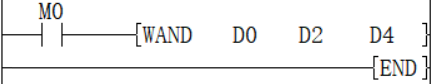
When M0 is set, the logical AND operation of (D0) and (D2) is performed, and the value is stored in (D4), that is, (D0) ∧ (D2) → (D4).
DAND/32-bit data logic AND
DAND(P)
Perform a logical AND operation on each bit of the BIN 32-bit data of the device specified in (S1) and the BIN 32-bit data of the device specified in (S2), and store the result in the device specified in (D).
-[DAND (S1) (S2) (D)]
Content, range and data type
| Parameter | Content | Range | Data type | Data type (label) |
| (S1) | Store the data for logical AND operation or the device storing the data | -2147483648 to +2147483647 | Signed BIN32 | ANY32_S |
| (S2) | Store the data for logical AND operation or the device storing the data | -2147483648 to +2147483647 | Signed BIN32 | ANY32_S |
| (D) | Device for storing logic and result | Signed BIN32 | ANY32_S |
Device used
| Instruction | Parameter | Devices | Offset modification | Pulse extension | ||||||||||||
| KnX | KnY | KnM | KnS | T | C | D | R | SD | LC | HSC | K | H | [D] | XXP | ||
| DAND | Parameter 1 | ● | ● | ● | ● | ● | ● | ● | ● | ● | ● | ● | ● | ● | ● | ● |
| Parameter 2 | ● | ● | ● | ● | ● | ● | ● | ● | ● | ● | ● | ● | ● | ● | ● | |
| Parameter 3 | ● | ● | ● | ● | ● | ● | ● | ● | ● | ● | ● | ● | ||||
Features
Perform a logical AND operation on each bit of the BIN 32-bit data of the device specified in (S1) and the BIN 32-bit data of the device specified in (S2), and store the result in the device specified in (D).
In the case of bit devices, bit devices after the number of points specified by the number of digits will be calculated as 0.
Error code
| Error code | Content |
| 4085H | The output results of (S1) and (S2) in the read application instruction exceed the device range |
| 4086H | The output result of (D) in the write application instruction exceeds the device range |
Example
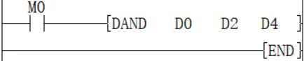
When M0 is set, perform logical AND operation of (D1, D0) and (D3, D2), and store the value in (D5, D4), (D1, D0) ∧ (D3, D2) → (D5, D4) .
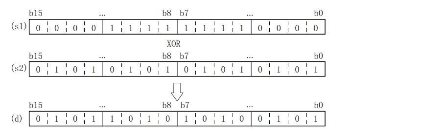
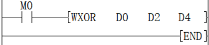
WXOR/16-bit data logic exclusive OR
WXOR(P)
Perform an exclusive OR operation on the BIN 16-bit data of the device specified in (S1) and the BIN 16-bit data of the device specified in (S2), and store the result in the device specified in (D).
-[WXOR (S1) (S2) (D)]
Content, range and data type
| Parameter | Content | Range | Data type | Data type (label) |
| (S1) | Store the data for exclusive OR operation or the device storing the data | -32768 to 32767 | Signed BIN16 | ANY16_S |
| (S2) | Store the data for exclusive OR operation or the device storing the data | -32768 to +32767 | Signed BIN16 | ANY16_S |
| (D) | Device for storing XOR result | Signed BIN16 | ANY16_S |
Device used
| Instruction | Parameter | Devices | Offset modification | Pulse extension | ||||||||||
| KnX | KnY | KnM | KnS | T | C | D | R | SD | K | H | [D] | XXP | ||
| WXOR | Parameter 1 | ● | ● | ● | ● | ● | ● | ● | ● | ● | ● | ● | ● | ● |
| Parameter 2 | ● | ● | ● | ● | ● | ● | ● | ● | ● | ● | ● | ● | ● | |
| Parameter 3 | ● | ● | ● | ● | ● | ● | ● | ● | ● | ● | ||||
Features
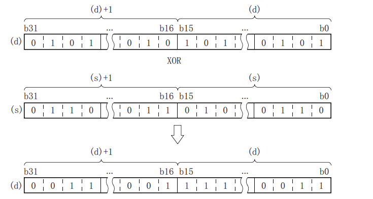
• Perform logical exclusive OR operation on the BIN 16-bit data of the device specified in (S1) and the BIN 16-bit data of the device specified in (S2), and store the result in the device specified in (D).
In the case of bit devices, bit devices after the number of points specified by the number of digits will be calculated as 0.
Error code
| Error code | Content |
| 4085H | The output results of (S1) and (S2) in the read application instruction exceed the device range |
| 4086H | The output result of (D) in the write application instruction exceeds the device range |
Example
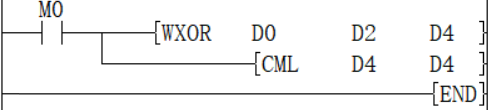
Example 1: When M0 is set, (D0) and (D2) are XOR operation, and the value is stored in (D4), (D0)∀(D2)→(D4).
Example 2: When used with the CML instruction, it can realize the logic exclusive OR (XORNOT) operation:
DXOR/32-bit data logic exclusive OR
DXOR(P)
Perform an exclusive OR operation on the BIN 32-bit data of the device specified in (S1) and the BIN 32-bit data of the device specified in (S2), and store the result in the device specified in (D).
-[DXOR (S1) (S2) (D)]
Content, range and data type
| Parameter | Content | Range | Data type | Data type (label) |
| (S1) | Store the data for exclusive OR operation or the device storing the data | -2147483648 to 2147483647 | Signed BIN32 | ANY32_S |
| (S2) | Store the data for exclusive OR operation or the device storing the data | -2147483648 to 2147483647 | Signed BIN32 | ANY32_S |
| (D) | Device for storing XOR result | Signed BIN32 | ANY32_S |
Device used
| Instruction | Parameter | Devices | Offset modification | Pulse extension | ||||||||||||
| KnX | KnY | KnM | KnS | T | C | D | R | SD | LC | HSC | K | H | [D] | XXP | ||
| DXOR | Parameter 1 | ● | ● | ● | ● | ● | ● | ● | ● | ● | ● | ● | ● | ● | ● | ● |
| Parameter 2 | ● | ● | ● | ● | ● | ● | ● | ● | ● | ● | ● | ● | ● | ● | ● | |
| Parameter 3 | ● | ● | ● | ● | ● | ● | ● | ● | ● | ● | ● | ● | ||||
Features
Perform an exclusive OR operation on the BIN 32-bit data of the device specified in (S1) and the BIN 32-bit data of the device specified in (S2), and store the result in the device specified in (D).
In the case of bit devices, bit devices after the number of points specified by the number of digits will be calculated as 0.
Error code
| Error code | Content |
| 4085H | The output results of (S1) and (S2)in the read application instruction exceed the device range |
| 4086H | The output result of (D) in the write application instruction exceeds the device range |
Example
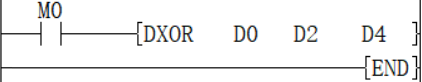
When M0 is set, (D1, D0) and (D3, D2) are XOR operation, and the value is stored in (D5, D4), that is, (D1, D0) ∀ (D3, D2) → (D5, D4) )
PRUN/8 digit transmission (16-bit data)
PRUN(P)
After processing the device numbers of (s) and (d) with designated digits as octal numbers, transfer the data.
-[PRUN (s) (d)]
Content, range and data type
| Parameter | Content | Range | data | Data type (label) |
| (s) | Digit designation*1 | - | BIN16 bit | ANY16 |
| (d) | Transfer destination device number*1 | - | BIN16 bit | ANY16 |
Device used
| Instruction | Parameter | Devices | Offset modification | Pulse extension | ||
| KnX | KnY | KnM | [D] | XXP | ||
| PRUN | Parameter 1 | ● | ● | ● | ● | |
| Parameter 2 | ● | ● | ● | ● | ||
Features
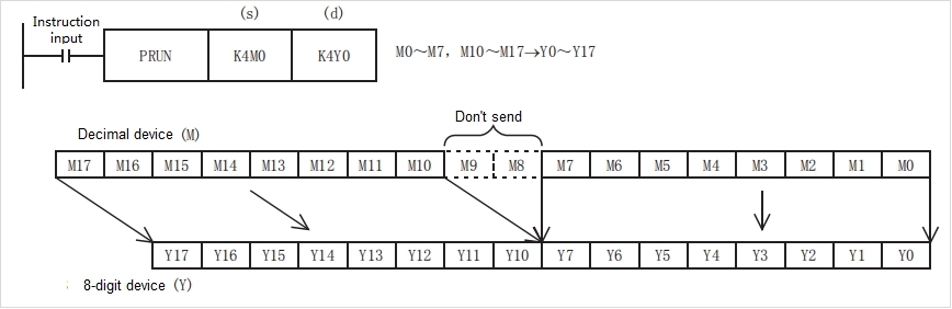
• 8-digit device → decimal device
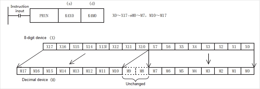
• Decimal digit device → octal digit device
Error code
| Error code | Content |
| 4085H | When reading the specified device range exceeds the corresponding device range |
| 4086H | When the specified device range for writing exceeds the range of the corresponding device |
Example
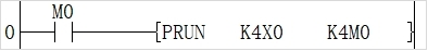
As shown in the above Circuit program:
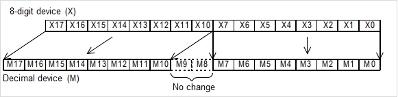
X0 to X17 take the value of octal digits and pass it to the Devices corresponding to M.
Data processing instructions
BCC/BIN16 and BIN8 bit data addition, subtraction and exclusive check
BCC (P)
Specify the calculation method of BCC in (S1), specify the destination start address in (S2), and specify the destination data length in (S3), and then store the operation result in the device specified in (D).
- [BCC (S1) (S2) (S3) (D)]
Content, range and data type
| Parameter | Content | Range | Data type | Data type (label) |
| (S1) | 16-bit constant or the calculation method of 16-bit regions (block check code) | 0 to 2 | BIN16 bit | ANY16_S |
| (S2) | Calculate the initial 16-bit regions of BCC | - | BIN16 bit | ANY16_S |
| (S3) | 16-bit constant or 16-bit regions (specify the number of bytes calculated by BCC) | 0 to 32767 | BIN16 bit | ANY16_S |
| (D) | Stores 16-bit regions of BCC results | - | BIN16 bit | ANY16_S |
Device used
| Instruction | Parameter | Devices | Offset modification | Pulse extension | ||||||||||
| KnX | KnY | KnM | KnS | T | C | D | R | SD | K | H | [D] | XXP | ||
| BCC | (S1) | ● | ● | ● | ● | ● | ● | ● | ● | ● | ● | ● | ● | ● |
| (S2) | ● | ● | ● | ● | ● | ● | ● | |||||||
| (S3) | ● | ● | ● | ● | ● | ● | ● | ● | ● | ● | ● | ● | ● | |
| (D) | ● | ● | ● | ● | ● | ● | ● | ● | ● | ● | ||||
Features
According to the calculation method specified by S1, starting from the 16-bit data specified by S2, calculate the ASCII block check code (BCC) of the number of bytes specified by S3, and then store the result of BCC code in the low byte of 16-bit data specified by D.
S1: Specify the calculation method of BCC.
K0: Addition operation
K1: Subtraction operation
K2: Exclusive or operation
S2 and s3: Specify the destination data
For example, if the destination is the 12 bytes data starting from D0, the settings are as below.
S2: D0
S3: K12 (specify the data by decimal)
The modes used in the calculation of this instruction are 16-bit conversion mode and 8-bit conversion mode. For the actions of each mode, refer to the followings.
(1) 16-bit conversion mode (When SM161 is OFF)
Calculate the high 8-bit (byte) and low 8-bit (byte) of device that started from (S2) and specify the byte length by (S3), and store the low 8-bit of device specified by (D). The conversion result is as below.
(2) 8-bit conversion mode (When SM161 is ON)
Calculate the low 8-bit (byte) of device that started from (S2) and specify the byte length by (S3), and store the low 8-bit of device specified by (D). The conversion result is as below.
Error code
| Error code | Content |
| 4084H | The read application instructions (S1) and (S3) input the data that exceeds the specified range |
| 4085H | The device specified in the read application instructions (S1), (S2) and (S3) exceeds the corresponding device range |
| 4086H | The device specified in the write application instruction (D) exceeds the corresponding device range |
Example
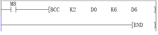
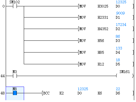
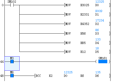
When the trigger M0 is ON, calculate the a block check code (BCC) of 12-bit bytes of ASCII data starting from data register D0 by “exclusive or operation”. The block check code (BCC) is stored in the low bit byte of data register D6.
Application example
In the example ,calculate the BCC code and send as information after adding to the string “%01→RC”.
The data transmission is carried out in the form of ASCII codes.
CC calculations use logical exclusive OR, addition, and subtraction.
The information is stored as follows:
| Data register | D6 | D2 | D1 | D0 |
| ASCII hexadecimal code | 4 3 5 2 | 2 3 3 1 | 3 0 2 5 | |
| ASCII code | C R | # 1 | 0 % |

↑
BCC check code 6 byte
BCC instruction is as below: Execution or operation
| a | b | OR result |
| 0 | 0 | 0 |
| 0 | 1 | 1 |
| 1 | 0 | 1 |
| 1 | 1 | 0 |


S1: logic exclusive OR
S2: The start of destination data
S3: destination data lengt
D: calculation result
After the execution BCC code is stored in the last byte of D6.
How to calculate block check code (BCC)
Calculate block check code (BCD) with XOR for each ASCII code.
BCC code
| ASCII hexadecimal code | 1 | 6 |
| ASCII binary code | 0 0 0 1 | 0 1 1 0 |
The calculation result is stored in the low bit byte of D6
MAX/BIN16 bit the maximum value of 16-bit data
MAX (P)
Specify the destination start address in (S1), and specify the destination end address in (S2), and then store the operation result in the device specified in (D).
- [MAX (S1) (S2) (D)]
Content, range and data type
| Parameter | Content | Range | Data type | Data type (label) |
| (S1) | Device that stores the start address when getting the max data | -32768 to 32767 | Signed BIN16 | ANY16_S |
| (S2) | Device that stores the end address when getting the max data | -32768 to 32767 | Signed BIN16 | ANY16_S |
| (D) | Stores the max value between the device data of (S1) and (S2) | -32768 to 32767 | Signed BIN16 | ANY16_S |
Device used
| Instruction | Parameter | Devices | Offset modification | Pulse extension | ||||
| T | C | D | R | SD | [D] | XXP | ||
| MAX | (S1) | ● | ● | ● | ● | ● | ● | ● |
| (S2) | ● | ● | ● | ● | ● | ● | ● | |
| (D) | ● | ● | ● | ● | ● | ● | ● | |
Features
Use the BIN16 bit data specified in (S1) as the start address, and use the BIN16 bit data specified in (S2) as the end address to get the maximum value between the device of (S1) and (S2).
Error code
| Error code | Content |
| 4084H | The read application instructions (S1) and (S2) input the data that exceeds the specified range |
| 4085H | The device specified in the read application instructions (S1) and (S2) exceeds the device range |
| 4086H | The device specified in the write application instruction (D) exceeds the device range |
| 4093H | The specified ranges (S1) and (S2) are not the same device |
| 4094H | The sequence of specified ranges (S1) and (S2) is abnormal |
Example
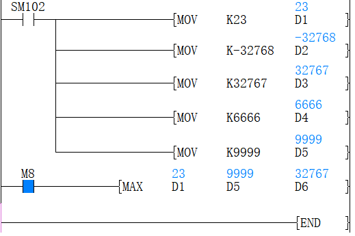
Use (D1) as the start address, and use (D5) as the end address to get the max value between them and store the result in (D6). As the figure above, the max value between (D1) and (D5) is the value in (D3) which is stored in (D6) for output.
DMAX/BIN32 bit the maximum value of 32-bit data
DMAX (P)
Specify the destination start address in (S1), and specify the destination end address in (S2), and then store the operation result in the device specified in (D).
- [DMAX (S1) (S2) (D)]
Content, range and data type
| Parameter | Content | Range | Data type | Data type (label) |
| (S1) | Device that stores the start address when getting the max data | -2147483648 to 2147483647 | Signed BIN32 | ANY32_S |
| (S2) | Device that stores the end address when getting the max data | -2147483648 to 2147483647 | Signed BIN32 | ANY32_S |
| (D) | Stores the max value between the device data of (S1) and (S2) | -2147483648 to 2147483647 | Signed BIN32 | ANY32_S |
Device used
| Instruction | Parameter | Devices | Offset modification | Pulse extension | ||||||
| T | C | D | R | SD | LC | HSC | [D] | XXP | ||
| DMAX | (S1) | ● | ● | ● | ● | ● | ● | ● | ● | ● |
| (S2) | ● | ● | ● | ● | ● | ● | ● | ● | ● | |
| (D) | ● | ● | ● | ● | ● | ● | ● | ● | ● | |
Features
Use the BIN32 bit data specified in (S1) as the start address, and use the BIN32 bit data specified in (S2) as the end address to get the maximum value between the device of (S1) and (S2).
Error code
| Error code | Content |
| 4084H | The read application instructions (S1) and (S2) input the data that exceeds the speicified range |
| 4085H | The device specified in the read application instructions (s1) and (S2) exceeds the device range |
| 4086H | The device specified in the write application instruction (D) exceeds the device range |
| 4093H | The specified ranges (S1) and (S2) are not the same device |
| 4094H | The sequence of specified ranges (S1) and (S2) is abnormal |
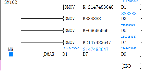
Example
Use (D1) as the start address, and use (D7) as the end address to get the max value between them and store the result in (D9). As the figure above, the max value between (D1) and (D7) is the value in (D7) which is stores in (D9) for output.
MIN/BIN16 bit the minimum value of 16-bit data
MIN (P)
Specify the destination start address in (S1), and specify the destination end address in (S2), and then store the operation result in the device specified in (D).
- [MIN (S1) (S2) (D)]
Content, range and data type
| Parameter | Content | Range | Data type | Data type (label) |
| (S1) | Device that stores the start address when getting the minimum data | -32768 to 32767 | Signed BIN16 | ANY16_S |
| (S2) | Device that stores the end address when getting the minimum data | -32768 to 32767 | Signed BIN16 | ANY16_S |
| (D) | Stores the minimum value between the device data of (S1) and (S2) | -32768 to 32767 | Signed BIN16 | ANY16_S |
Device used
| Instruction | Parameter | Devices | Offset modification | Pulse extension | ||||
| T | C | D | R | SD | [D] | XXP | ||
| MIN | (S1) | ● | ● | ● | ● | ● | ● | ● |
| (S2) | ● | ● | ● | ● | ● | ● | ● | |
| (D) | ● | ● | ● | ● | ● | ● | ● | |
Features
Use the BIN16 bit data specified in (S1) as the start address, and use the BIN16 bit data specified in (S2) as the end address to get the maximum value between the device of (S1) and (S2).
✎Note
1. The devices specified by (S1) and (S2) should be the same type. The type of device (D) that gets the results could be different.
2. The device size specified by (S1) can’t exceed the device size specified by (S2). For example, MAX D1 D5 D10 works, but MAX D5 D1 D10 doesn't.
Error code
| Error code | Content |
| 4084H | The read application instructions (S1) and (S2) input the data that exceeds the specified range |
| 4085H | The device specified in the read application instructions (S1) and (S2) exceeds the device range |
| 4086H | The device specified in the write application instruction (D) exceeds the device range |
| 4093H | The specified ranges (S1) and (S2) are not the same device |
| 4094H | The sequence of specified ranges (S1) and (S2) is abnormal |
Example
Use (D1) as the start address, and use (D5) as the end address to get the max value between them and store the result in (D6). As the figure above, the max value between (D1) and (D5) is the value in (D3) which is stored in (D6) for output.
DMIN/BIN32 bit the minimum value of 32-bit data
DMIN (P)
Specify the destination start address in (S1), and specify the destination end address in (S2), and then store the operation result in the device specified in (D).
- [DMIN (S1) (S2) (D)]
Content, range and data type
| Parameter | Content | Range | Data type | Data type (label) |
| (S1) | Device that stores the start address when getting the minimum data | -2147483648 to 2147483647 | Signed BIN16 | ANY16_S |
| (S2) | Device that stores the end address when getting the minimum data | -2147483648 to 2147483647 | Signed BIN16 | ANY16_S |
| (D) | Stores the minimum value between the device data of (S1) and (S2) | -2147483648 to 2147483647 | Signed BIN16 | ANY16_S |
Device used
| Instruction | Parameter | Devices | Offset modification | Pulse extension | ||||
| T | C | D | R | SD | [D] | XXP | ||
| DMIN | (S1) | ● | ● | ● | ● | ● | ● | ● |
| (S2) | ● | ● | ● | ● | ● | ● | ● | |
| (D) | ● | ● | ● | ● | ● | ● | ● | |
Features
Use the BIN32 bit data specified in (S1) as the start address, and use the BIN32 bit data specified in (S2) as the end address to get the maximum value between the device of (S1) and (S2).
✎Note
1. The devices specified by (S1) and (S2) should be the same type. The type of device (D) that gets the results could be different.
2. The device size specified by (S1) can’t exceed the device size specified by (S2). For example, MAX D1 D5 D10 works, but MAX D5 D1 D10 doesn't.
Error code
| Error code | Content |
| 4084H | The read application instructions (S1) and (S2) input the data that exceeds the specified range |
| 4085H | The device specified in the read application instructions (S1) and (S2) exceeds the device range |
| 4086H | The device specified in the write application instruction (D) exceeds the device range |
| 4093H | The specified ranges (S1) and (S2) are not the same device |
| 4094H | The sequence of specified ranges (S1) and (S2) is abnormal |
Example
Use (D1) as the start address, and use (D5) as the end address to get the max value between them and store the result in (D6). As the figure above, the max value between (D1) and (D5) is the value in (D3) which is stored in (D6) for output.
ANS/alarm settings
ANS(P)
Used to set alarm instructions.
-[ANS (S) (N) (D)]
Content, range and data type
| Parameter | Content | Range | Data type | Data type (label) |
| (S) | Timer number for judging time | - | Signed BIN 16 bit | ANY16 |
| (N) | Data that judges time | 1 to 32767 | Signed BIN 16 bit | ANY16 |
| (D) | The set alarm device | - | Bit | ANY16_BOOL |
Device used
| Instruction | Parameter | Devices | Offset modification | Pulse extension | |||||||||||
| S | KnX | KnY | KnM | KnS | T | C | D | R | SD | K | H | [D] | XXP | ||
| ANS | Parameter 1 | ● | ● | ● | |||||||||||
| Parameter 2 | ● | ● | ● | ● | ● | ● | ● | ● | ● | ● | ● | ● | ● | ||
| Parameter 3 | ● | ● | ● | ||||||||||||
Features
When the instruction input continues to be ON for the judgment time [(N)×100ms, timer (S)], set (D). If the instruction time turns off below the judgment time [(N)×100ms], the current value of the judgment timer (S) is reset, and (D) is not set. In addition, if the instruction input turns off, the judgment timer will be reset.
1. Judge the time ((N)X 100ms or less)
2. Judgment time or more (inclusive) ((N) X 100ms or more (inclusive))
Related device
| Devices | Name | Content |
| SM249 | Signal alarm is valid | After SM249 is ON, the following SM248 and SD249 act. |
| SM248 | Signal alarm action | SM249 is ON, when any one of the states S900 to S999 is active, SM248 is ON |
| SD249 | Signal alarm ON state minimum number | Save the smallest number of actions in S900 to S999. |
Error code
| Error code | Content |
| 4084H | The value specified in (N1) and (N2) exceeds the range of 0 to 32767 |
| The timer number is not in the range of T0 to T199. | |
| The signal alarm is not in the range of S900 to S999. | |
| 4085H | When the device specified in the read application instructions (S) and (N) exceeds the corresponding device range |
| 4086H | When the device specified in the write application instruction (D) exceeds the corresponding device range |
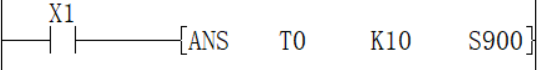
Example
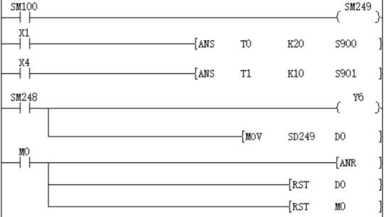
The fault number is displayed by the signal alarm.
Monitoring is effective after SM249 is turned ON
As shown below, when you write a program for diagnosing external faults, such as monitoring the content of SM249 (the smallest number in the ON state), the smallest number in the ON state among S900 to S999 will be displayed. When multiple faults occur at the same time, the next fault number can be obtained after eliminating the fault with the smallest number.
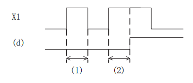
Detect X1 for 2 seconds, turn ON, set S900
X4 is detected for 1 second, turn ON, set S901
SM248 will act after any one of S900 to S999 is ON, and the output fault display YY6 will act
Display the fault number to the D0 device
Through the external fault diagnosis program, use the reset button M0 to turn off the activated state. Each time M0 turns ON, the action status of the new number is set in turn, and the new number that is already ON is reset.
ANR/Alarm reset
ANR(P)
The instruction to reset the small number that is ON in the alarm.
-[ANR]
Content, range and data type
| Parameter | Content | Range | Data type | Data type (label) |
| No | No parameter setting | - | - | - |
Device used
| Instruction | Parameter | Devices | Offset modification | Pulse extension | |||||||||||||||||||||||
| X | Y | M | S | SM | T(bit) | C(bit) | LC(bit) | HSC(bit) | D.b | KnX | KnY | KnM | KnS | T | C | D | R | SD | LC | HSC | K | H | E | [D] | XXP | ||
| ANR | No | No object device | |||||||||||||||||||||||||
Features
If the instruction input is ON, reset the active alarm in the alarm.
If multiple alarms are operating, reset the smaller number. If the input instruction is turned ON again, the next small number in the alarm that is operating will be reset.
Related device
| Devices | Name | Content |
| SM249 | Signal alarm is valid | After SM249 is ON, the following SM248 and SD249 act. |
| SM248 | Signal alarm action | SM249 is ON, when any one of the states S900 to S999 is active, SM248 is ON. |
| SD249 | Signal alarm ON state minimum number | Save the smallest number of actions in S900 to S999. |
✎Note:
If you use the ANR instruction, reset in sequence every cycle.
If the ANRP instruction is used, it will be executed in only one operation cycle.
Error code
No operation error.
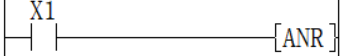
Example
The fault number is displayed by the signal alarm.
As shown below, when you write a program for diagnosing external faults, such as monitoring the content of SM249 (the smallest number in the ON state), the smallest number in the ON state among S900 to S999 will be displayed. When multiple faults occur at the same time, the next fault number can be obtained after eliminating the fault with the smallest number.
Monitoring is effective after SM249 is turned ON
Detect X1 for 2 seconds, turn ON, set S900
X4 is detected for 1 second, turn ON, set S901
SM248 will act after any one of S900 to S999 is ON, and the output fault display YY6 will act
Display the fault number to the D0 device
Through the external fault diagnosis program, use the reset button M0 to turn off the activated state. Each time M0 turns ON, the action status of the new number is set in turn, and the new number that is already ON is reset.
BON/16-bit data bit judgment
BON(P)
Check whether the state of the BIN 16-bit data (N) bit of the device specified in (S) is ON or OFF, and output the result to the device specified in (D).
-[BON (S) (N) (D)]
Content, range and data type
| Parameter | Content | Range | Data type | Data type (label) |
| (S) | Data storage destination word device number | - | Signed BIN 16 bit | ANY16 |
| (D) | Bit device number of drive | - | Bit | ANY16_BOOL |
| (N) | The position of the bit to be judged | 0 to 15 | Signed BIN 16 bit | ANY16 |
Device used
| Instruction | Parameter | Devices | Offset modification | Pulse extension | |||||||||||||||
| Y | M | S | SM | D.b | KnX | KnY | KnM | KnS | T | C | D | R | SD | K | H | [D] | XXP | ||
| BON | Parameter 1 | ● | ● | ● | ● | ● | ● | ● | ● | ● | ● | ● | ● | ● | |||||
| Parameter 2 | ● | ● | ● | ● | ● | ● | ● | ● | ● | ● | |||||||||
| Parameter 3 | ● | ● | ● | ● | ● | ● | ● | ● | ● | ● | ● | ● | ● | ||||||
Features
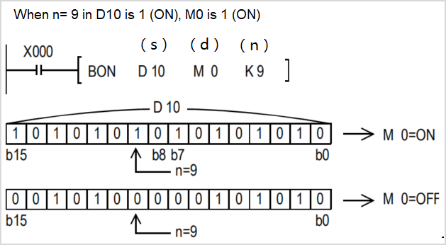
Check whether the state of the BIN 16-bit data (N) bit of the device specified in (S) is ON or OFF, and output the result to the device specified in (D).
If the above result is ON, then (D)=ON, if it is OFF, then (D)=OFF.
If a constant (K) is specified in the device specified in (S), it will be automatically converted to BIN.
Error code
| Error code | Content |
| 4084H | The data input in (N) exceeds the specified range of 0 to 15. |
| 4085H | When the device specified in the read application instructions (S) and (N) exceeds the corresponding device range |
| 4086H | When the device specified in the write application instruction (D) exceeds the corresponding device range |
Example
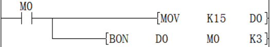
When n in D0 = the third bit is 1 (ON), M0 is set to 1 (ON).
DBON/32-bit data bit judgment
DBON(P)
Check whether the state of the BIN 32-bit data (N) bit of the device specified in (S) is ON or OFF, and output the result to the device specified in (D).
-[DBON (S) (N) (D)]
Content, range and data type
| Parameter | Content | Range | Data type | Data type (label) |
| (S) | Data storage destination word device number | - | Signed BIN 32 bit | ANY32 |
| (D) | Bit device number of drive | - | Bit | ANY32_BOOL |
| (N) | The position of the bit to be judged | 0 to 31 | Signed BIN 32 bit | ANY32 |
Device used
| Instruction | Parameter | Devices | Offset modification | Pulse extension | |||||||||||||||||
| Y | M | S | SM | D.b | KnX | KnY | KnM | KnS | T | C | D | R | SD | LC | HSC | K | H | [D] | XXP | ||
| DBON | Parameter 1 | ● | ● | ● | ● | ● | ● | ● | ● | ● | ● | ● | ● | ● | ● | ● | |||||
| Parameter 2 | ● | ● | ● | ● | ● | ● | ● | ● | ● | ● | |||||||||||
| Parameter 3 | ● | ● | ● | ● | ● | ● | ● | ● | ● | ● | ● | ● | ● | ● | ● | ||||||
Features
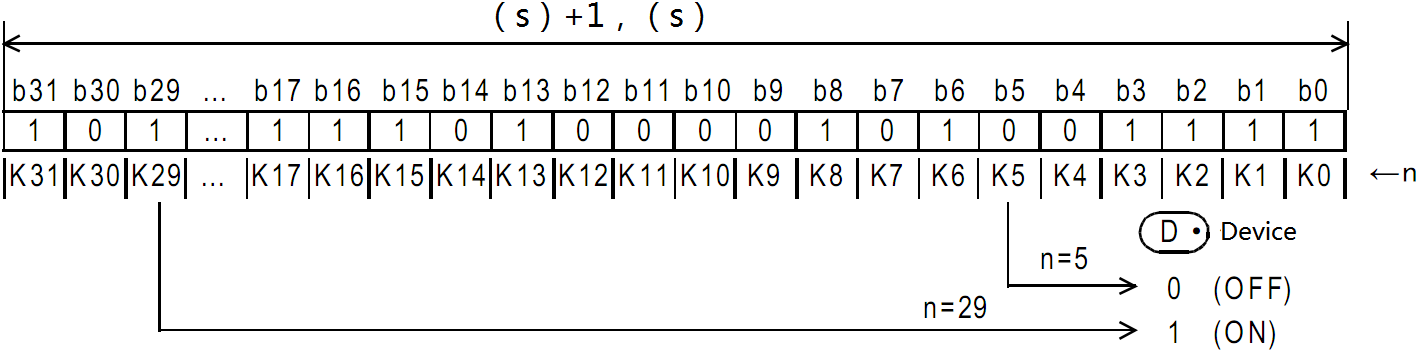
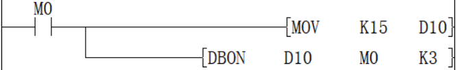
Check whether the BIN 32-bit data (N) bit status of the device specified in (S) is ON or OFF, and output the result to the device specified in (D).
If the above result is ON, then (D)=ON, if it is OFF, then (D)=OFF.
If a constant (K) is specified in the device specified in (S), it will be automatically converted to BIN.
Error code
| Error code | Content |
| 4084H | The data input in (N) exceeds the specified range of 0 to 31. |
| 4085H | When the device specified in the read application instructions (S) and (N) exceeds the corresponding device range |
| 4086H | When the device specified in the write application instruction (D) exceeds the corresponding device range |
Example
When n in D0 = the third bit is 1 (ON), M0 is set to 1 (ON).
ENCO/Encode
ENCO(P)
Encode the data of the 2th (N)th power from (S) and store it in (D).
-[ENCO (S) (N) (D)]
Content, range and data type
| Parameter | Content | Range | Data type | Data type (label) |
| (S) | Start device for storing coded data | - | Bit/Signed BIN 16 bit | ANY_ELEMENTARY |
| (D) | Device number storing the encoding result | - | Signed BIN 16 bit | ANY_ELEMENTARY |
| (N) | Effective bit length | 0 to 8 | Signed BIN 16 bit | ANY16 |
Device used
| Instruction | Parameter | Devices | Offset modification | Pulse extension | |||||||||||||||
| X | Y | M | S | SM | KnX | KnY | KnM | KnS | T | C | D | R | SD | K | H | [D] | XXP | ||
| ENCO | Parameter 1 | ● | ● | ● | ● | ● | ● | ● | ● | ● | ● | ● | ● | ||||||
| Parameter 2 | ● | ● | ● | ● | ● | ● | ● | ● | ● | ● | |||||||||
| Parameter 3 | ● | ● | ● | ● | ● | ● | ● | ● | ● | ● | ● | ● | ● | ||||||
Features
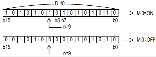
The BIN value corresponding to the bit from 2 (N) bits of (S) to 1 is stored in (D).
When (N)=0, it will be no processing, and the content of the device specified in (D) will not change.
Bit devices are treated as 1 bit, and word devices are treated as 16 bits.
When multiple digits are 1, it will be processed at the upper position.
Error code
| Error code | Content |
| 4084H | In the bit device specification of (S), when (N) is other than 0 to 8. |
| In the word device specification of (S), when (N) is other than 0 to 4. | |
| When the data of 2(N) bits starting from (S) are all 0. | |
| 4085H | When the device specified in the read application instructions (S) and (N) exceeds the corresponding device range |
| 4086H | When the device specified in the write application instruction (D) exceeds the corresponding device range |
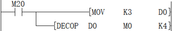
Example
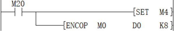
When M20 is turned ON, the D0 device is 16 after encoding.
DECO/Decode
DECO(P)
Decode the lower (N) bits of the device specified in (S), and store the result in the 2 (N)th power of the device specified in (D).
-[DECO (S) (N) (D)]
Content, range and data type
| Parameter | Content | Range | Data type | Data type (label) |
| (S) | Decoded data or the device number storing the decoded data | - | Bit/Signed BIN 16 bit | ANY_ELEMENTARY |
| (D) | The start device storing the decoding result | - | Signed BIN 16 bit | ANY_ELEMENTARY |
| (N) | Effective bit length | 0 to 8 | Signed BIN 16 bit | ANY16 |
Device used
| Instruction | Parameter | Devices | Offset modification | Pulse extension | |||||||||||||||
| X | Y | M | S | SM | KnX | KnY | KnM | KnS | T | C | D | R | SD | K | H | [D] | XXP | ||
| DECO | Parameter 1 | ● | ● | ● | ● | ● | ● | ● | ● | ● | ● | ● | ● | ● | ● | ● | ● | ● | |
| Parameter 2 | ● | ● | ● | ● | ● | ● | ● | ● | ● | ● | ● | ||||||||
| Parameter 3 | ● | ● | ● | ● | ● | ● | ● | ● | ● | ● | ● | ● | ● | ||||||
Features
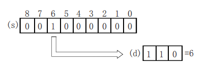
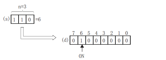
Turn ON the position of (D) corresponding to the BIN value specified in the lower (N) bit of (S).
When (N)=0, it will be no processing, and the content of the device specified in (D) will not change.
Bit devices are treated as 1 bit, and word devices are treated as 16 bits.
Error code
| Error code | Content |
| 4084H | In the bit device specification of (D), when (N) is other than 0 to 8. |
| In the word device specification of (D), when (N) is other than 0 to 4. | |
| 4085H | When the device specified in the read application instructions (S) and (N) exceeds the corresponding device range |
| 4086H | When the device specified in the write application instruction (D) exceeds the corresponding device range |
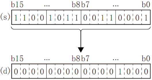
Example
When M20 is ON, M3 will be turned ON.
SUM/The ON bits of 16-bit data
SUM(P)
Store the total number of bits at 1 in the BIN 16-bit data of the device specified in (S) to the device specified in (D).
-[SUM (S) (D)]
Content, range and data type
| Parameter | Content | Range | Data type | Data type (label) |
| (S) | The device start number that counts the total number of bits at 1 | - | Signed BIN 16 bit | ANY16 |
| (D) | The device start number of the total number of storage bits | - | Signed BIN 16 bit | ANY16 |
Device used
| Instruction | Parameter | Devices | Offset modification | Pulse extension | ||||||||||
| KnX | KnY | KnM | KnS | T | C | D | R | SD | K | H | [D] | XXP | ||
| SUM | Parameter 1 | ● | ● | ● | ● | ● | ● | ● | ● | ● | ● | ● | ● | ● |
| Parameter 2 | ● | ● | ● | ● | ● | ● | ● | ● | ● | ● | ||||
Features
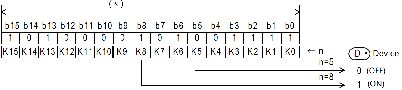
Store the total number of bits at 1 in the BIN 16-bit data of the device specified in (S) to the device specified in (D).
When the BIN 16-bit data of the device specified in (S) is all 0, the zero flag (SM153) turns on.
The total number of 1 (ON) is stored in BIN.
There are 8 in the example on the left.
Error code
| Error code | Content |
| 4085H | When the device specified in the read application instructions (S) exceeds the corresponding device range |
| 4086H | When the device specified in the write application instruction (D) exceeds the corresponding device range |
Example
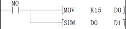
When M0 is ON, the number of ON bits in D0 is counted and stored in D1. The value after D1 is executed is 4.
DSUM/The ON bits of 32-bit data
DSUM(P)
Store the total number of bits at 1 in the BIN 32-bit data of the device specified in (S) to the device specified in (D).
-[SUM (S) (D)]
Content, range and data type
| Parameter | Content | Range | Data type | Data type (label) |
| (S) | The device start number that counts the total number of bits at 1 | - | Signed BIN 32 bit | ANY32 |
| (D) | The device start number of the total number of storage bits | - | Signed BIN 32 bit | ANY32 |
Device used
| Instruction | Parameter | Devices | Offset modification | Pulse extension | ||||||||||||
| KnX | KnY | KnM | KnS | T | C | D | R | SD | LC | HSC | K | H | [D] | XXP | ||
| DSUM | Parameter 1 | ● | ● | ● | ● | ● | ● | ● | ● | ● | ● | ● | ● | ● | ● | ● |
| Parameter 2 | ● | ● | ● | ● | ● | ● | ● | ● | ● | ● | ● | ● | ||||
Features
Store the total number of bits at 1 in the BIN 32-bit data of the device specified in (S) to the device specified in (D).
When the BIN 32-bit data of the device specified in (S) is all 0 (OFF), the zero flag (SM153) turns on.
The total number of 1 (ON) is stored in BIN.
There are 16 in the example on the left.
✎Note: When the instruction input is OFF, the instruction will not be executed, and the output of the ON digits of the action will remain the same as before.
Error code
| Error code | Content |
| 4085H | When the device specified in the read application instructions (S) exceeds the corresponding device range |
| 4086H | When the device specified in the write application instruction (D) exceeds the corresponding device range |
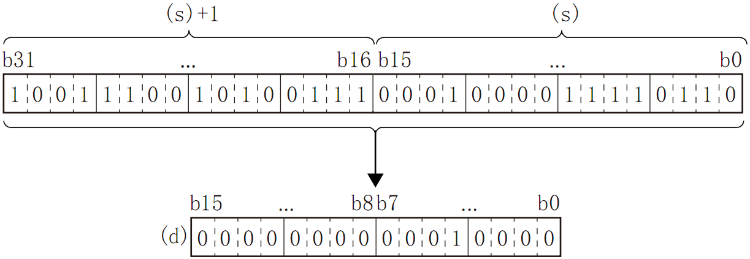
Example
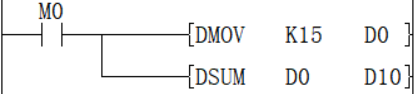
When M0 is ON, the number of ON bits in D0 is counted and stored in D10, and the value after D10 is executed is 4.
MEAN/Mean value of 16-bit data
MEAN(P)
Store the total number of bits at 1 in the BIN 16-bit data of the device specified in (S) to the device specified in (D).
-[MEAN (S) (D) (N)]
Content, range and data type
| Parameter | Content | Range | Data type | Data type (label) |
| (S) | The device start number storing the data for average calculation | - | Signed BIN 16 bit | ANY16 |
| (D) | The device start number storing the average value | - | Signed BIN 16 bit | ANY16 |
| (N) | Number of data or the device number storing the number of data | 1 to 32767 | Signed BIN 16 bit | ANY16 |
Device used
| Instruction | Parameter | Devices | Offset modification | Pulse extension | ||||||||||
| KnX | KnY | KnM | KnS | T | C | D | R | SD | K | H | [D] | XXP | ||
| MEAN | Parameter 1 | ● | ● | ● | ● | ● | ● | ● | ● | ● | ● | ● | ||
| Parameter 2 | ● | ● | ● | ● | ● | ● | ● | ● | ● | ● | ||||
| Parameter 3 | ● | ● | ● | ● | ● | ● | ● | ● | ● | ● | ● | ● | ● | |
Features
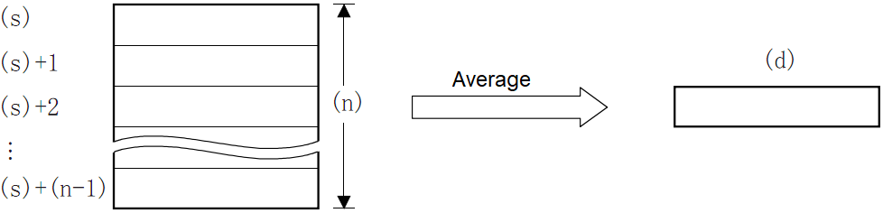
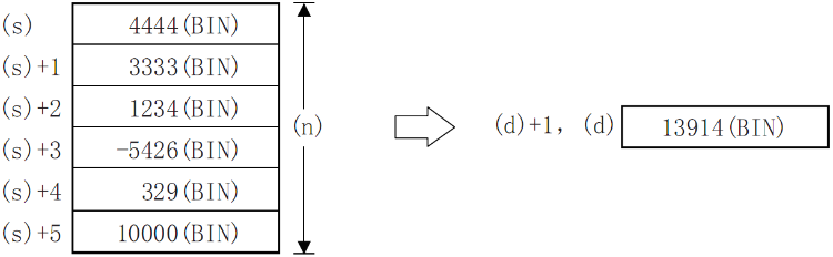
Calculate the average value of the 16-bit data at (N) points starting from the device specified in (S) and store it in the device specified in (D).
The total is calculated from the algebraic sum and divided by (N).
The remainder is rounded off.
Error code
| Error code | Content |
| 4084H | The data input by (N) in the application instruction exceeds the specifiable range. N≤0 |
| 4085H | When the device specified in the read application instructions (S) and (N) exceeds the corresponding device range |
| 4086H | When the device specified in the write application instruction (D) exceeds the corresponding device range |
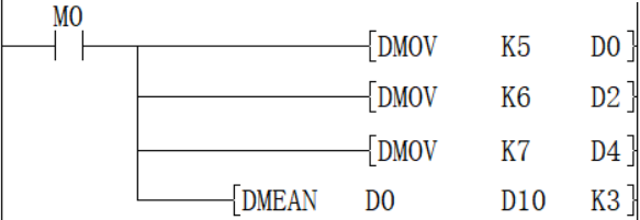
Example
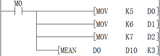
Add the data of D0, D1, and D2 and save the value obtained after dividing by 3 in D10. The calculated average value is 6.
DMEAN/Mean value of 16-bit data
DMEAN(P)
Store the total number of bits at 1 in the BIN 32-bit data of the device specified in (S) to the device specified in (D).
-[DMEAN (S) (D) (N)]
Content, range and data type
| Parameter | Content | Range | Data type | Data type (label) |
| (S) | The device start number storing the data for average calculation | - | Signed BIN 32 bit | ANY32 |
| (D) | The device start number storing the average value | - | Signed BIN 32 bit | ANY32 |
| (N) | Number of data or the device number storing the number of data | 1 to 2147483647 | Signed BIN 32 bit | ANY32 |
Device used
| Instruction | Parameter | Devices | Offset modification | Pulse extension | ||||||||||||
| KnX | KnY | KnM | KnS | T | C | D | R | SD | LC | HSC | K | H | [D] | XXP | ||
| DMEAN | Parameter 1 | ● | ● | ● | ● | ● | ● | ● | ● | ● | ● | ● | ● | ● | ||
| Parameter 2 | ● | ● | ● | ● | ● | ● | ● | ● | ● | ● | ● | ● | ||||
| Parameter 3 | ● | ● | ● | ● | ● | ● | ● | ● | ● | ● | ● | ● | ● | ● | ● | |
Features
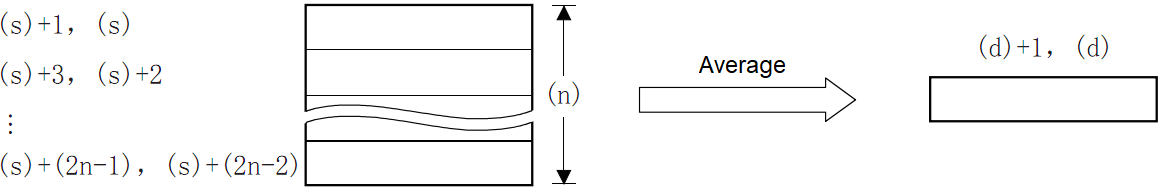
Calculate the mean value of BIN 32-bit data at (N) points starting from the device specified in (S) and store it in the device specified in (D).
The total is calculated from the algebraic sum and divided by (N).
The remainder is rounded off.
✎Note: When the device number exceeds, (N) is handled as a smaller value within the allowable range.
Error code
| Error code | Content |
| 4084H | The data input in (N) exceeds the specifiable range. N≤0 |
| 4085H | When the device specified in the read application instructions (S) and (N) exceeds the corresponding device range |
| 4086H | When the device specified in the write application instruction (D) exceeds the corresponding device range |
Example
Add the data of D0, D2, and D4, and save the value obtained after dividing by 3 in D10 and D11, and the calculated average value is 6.
SQR/16-bit square root
SQR(P)
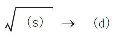
Calculate the square root of the BIN 16-bit data specified in (S), and store the calculation result in (D).
-[SQR (S) (D)]
Content, range and data type
| Parameter | Content | Range | Data type | Data type (label) |
| (S) | The data device storing for square root calculation | 0 to +32767 | Signed BIN 16 bit | ANY16 |
| (D) | The device storing the calculated square root | - | Signed BIN 16 bit | ANY16 |
Device used
| Instruction | Parameter | Devices | Offset modification | Pulse extension | ||||
| D | R | SD | K | H | [D] | XXP | ||
| SQR | Parameter 1 | ● | ● | ● | ● | ● | ● | ● |
| Parameter 2 | ● | ● | ● | ● | ● | |||
Features
Calculate the square root of the BIN 16-bit data specified in (S), and store the calculation result in (D).
✎Note: The decimal point of operation result will be rounded off and become an integer. If rounding occurs, SM152 (borrow flag) turns ON.
When the operation result is really 0, SM153 (zero flag) turns ON.
Error code
| Error code | Content |
| 4084H | When a negative value is specified in (S). |
| 4085H | When the device specified in the read application instructions (S) exceeds the corresponding device range |
| 4086H | When the device specified in the write application instruction (D) exceeds the corresponding device range |
Example
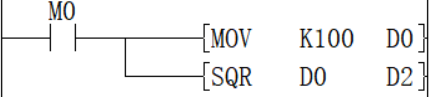
The square root of D0 is stored in D2, and the value of D0 is 100, so the value of D2 is 10.
DSQR/32-bit square root
DSQR(P)
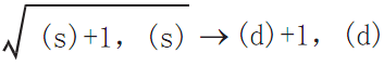
Calculate the square root of the BIN 32-bit data specified in (S), and store the calculation result in (D).
-[DSQR (S) (D)]
Content, range and data type
| Parameter | Content | Range | Data type | Data type (label) |
| (S) | The data device storing for square root calculation | 0 to 2147483647 | Signed BIN 32 bit | ANY32 |
| (D) | The device storing the calculated square root | - | Signed BIN 32 bit | ANY32 |
Device used
| Instruction | Parameter | Devices | Offset modification | Pulse extension | ||||||
| D | R | SD | LC | HSC | K | H | [D] | XXP | ||
| DSQR | Parameter 1 | ● | ● | ● | ● | ● | ● | ● | ● | ● |
| Parameter 2 | ● | ● | ● | ● | ● | ● | ● | |||
Features
Calculate the square root of the BIN 32-bit data specified in (S) and store the calculation result in (D).
✎Note: The decimal point of operation result will be rounded off and become an integer. If rounding occurs, SM152 (borrow flag) turns ON.
When the operation result is really 0, SM153 (zero flag) turns on.
Error code
| Error code | Content |
| 4084H | When a negative value is specified in (S). |
| 4085H | When the device specified in the read application instructions (S) exceeds the corresponding device range |
| 4086H | When the device specified in the write application instruction (D) exceeds the corresponding device range |
Example
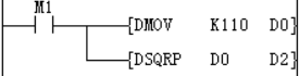
The square root of D0 is stored in D2, and the value of D0 is 110, so the value in the D2 soft component is 10 (the fractional part is discarded), and the borrow flag SM152 is turned ON.
WSUM/The sum value of 16-bit data
WSUM(P)
After adding all the BIN 16-bit data of point (n) starting from the device specified in (S), it is stored in the device specified in (D).
-[WSUM (S) (D) (N)]
Content, range and data type
| Parameter | Content | Range | Data type | Data type (label) |
| (S) | The device start number storing the data for sum value calculation | - | Signed BIN 16 bit | ANY16 |
| (D) | The device start number storing the sum value | - | Signed BIN 32 bit | ANY32 |
| (N) | Number of data | - | Signed BIN 16 bit | ANY16 |
Device used
| Instruction | Parameter | Devices | Offset modification | Pulse extension | ||||||||||
| KnX | KnY | KnM | KnS | T | C | D | R | SD | K | H | [D] | XXP | ||
| WSUM | Parameter 1 | ● | ● | ● | ● | ● | ● | ● | ||||||
| Parameter 2 | ● | ● | ● | ● | ● | ● | ● | ● | ● | ● | ||||
| Parameter 3 | ● | ● | ● | ● | ● | ● | ● | ● | ● | ● | ● | ● | ● | |
Features
After adding all the BIN 16-bit data of point (N) starting from the device specified in (S), it is stored in the device specified in (D).
Error code
| Error code | Content |
| 4084H | When a negative value is specified in (N). |
| 4085H | When the device specified in the read application instructions (S) and (N) exceeds the corresponding device range |
| 4086H | When the device specified in the write application instruction (D) exceeds the corresponding device range |
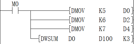
Example
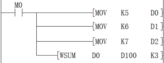
When M0=ON, the total of 16-bit data of D0 to D2 is saved in [D100, D101], and the accounting result is 18.
DWSUM/The sum value of 32-bit data
DWSUM(P)
Add all the 32-bit BIN data of point (N) starting from the device specified in (S) and store it in the device specified in (D).
-[DWSUM (S) (D) (N)]
Content, range and data type
| Parameter | Content | Range | Data type | Data type (label) |
| (S) | The device start number storing the data for total value calculation | - | Signed BIN 32 bit | ANY32 |
| (D) | The device start number storing the total value | - | Signed BIN64 bit | ANY64 |
| (N) | Number of data | - | Signed BIN 32 bit | ANY32 |
Device used
| Instruction | Parameter | Devices | Offset modification | Pulse extension | ||||||||||||
| KnX | KnY | KnM | KnS | T | C | D | R | SD | LC | HSC | K | H | [D] | XXP | ||
| DWSUM | Parameter 1 | ● | ● | ● | ● | ● | ● | ● | ● | ● | ||||||
| Parameter 2 | ● | ● | ● | ● | ● | ● | ● | ● | ● | ● | ● | ● | ||||
| Parameter 3 | ● | ● | ● | ● | ● | ● | ● | ● | ● | ● | ● | ● | ● | ● | ● | |
Features
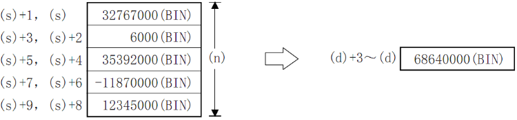
Add all the 32-bit BIN data of point (n) starting from the device specified in (s) and store it in the device specified in (d).
✎Note: When the number of bits is specified in (D), the value of n ranges from 1 to 8, such as K8 (32-bit instructions, such as K8M0) without K16 (64-bit instructions).
Error code
| Error code | Content |
| 4084H | When a negative value is specified in (N). |
| 4085H | When the device specified in the read application instructions (S) and (N) exceeds the corresponding device range |
| 4086H | When the device specified in the write application instruction (D) exceeds the corresponding device range |
Example
When M0=ON, the total of 16-bit data of D0 to D2 is saved in [D100, D101], and the accounting result is 18.
SORT/16-bit data sorting
SORT
Sort the data rows in ascending order based on the group data of column (N3) in the BIN 16-bit data table (sorting source) of (N1×N2) points specified in (S) and store them in the specified in (D) (N1×N2) points in the BIN 16-bit data table (after sorting).
-[SORT (S) (N1) (N2) (D) (N3)]
Content, range and data type
| Parameter | Content | Range | Data type | Data type (label) |
| (S) | The start device number storing the data table | - | Signed BIN 16 bit | ANY16 |
| (N1) | Number of data (rows) | 1 to 32 | Signed BIN 16 bit | ANY16 |
| (N2) | Number of group data (columns) | 1 to 6 | Signed BIN 16 bit | ANY16 |
| (D) | The start device number storing the operation result | - | Signed BIN 16 bit | ANY16 |
| (N3) | The column number of the group data (column) as the sorting basis | - | Signed BIN 16 bit | ANY16 |
Device used
| Instruction | Parameter | Devices | Offset modification | Pulse extension | ||||||||||
| KnX | KnY | KnM | KnS | T | C | D | R | SD | K | H | [D] | XXP | ||
| SORT | Parameter 1 | ● | ● | ● | ● | ● | ● | |||||||
| Parameter 2 | ● | ● | ● | ● | ● | ● | ● | ● | ● | ● | ● | ● | ||
| Parameter 3 | ● | ● | ● | ● | ● | ● | ● | ● | ● | ● | ● | ● | ||
| Parameter 4 | ● | ● | ● | ● | ● | ● | ||||||||
| Parameter 5 | ● | ● | ● | ● | ● | ● | ● | ● | ● | ● | ● | ● | ||
Features
The BIN 16-bit data table (sorting source) of (N1×N2) points specified in (S), based on the group data of column (N3), sort the data rows in ascending order, and store them in (D). The (N1×N2) point of the BIN 16-bit data table (after sorting).
Take (N1)=K3, (N2)=K4 in the sort source as an example, the data table structure is as follows. In the case of a sorted data table, (S) should be replaced with (D).
| Number of groups (N2) ((N2)=K4) | |||||
| Column NO. 1 | Column NO. 2 | Column NO. 3 | Column NO. 4 | ||
| Management number | Height | Weight | Age | ||
| When the number of data (N1)=3 | Line NO.1 | (S) | (S) +3 | (S) +6 | (S) +9 |
| Line NO.2 | (S)+1 | (S) +4 | (S) +7 | (S) +10 | |
| Line NO.3 | (S)+2 | (S) +5 | (S) +8 | (s) +11 | |
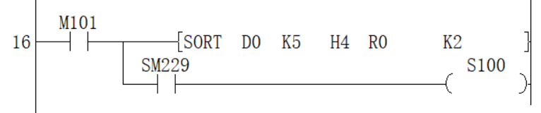
Data alignment starts when instruction input is ON, data alignment ends after (N1) scan, instruction execution end flag SM229 is set to ON. According to the source data sorted as follows, an example of the operation is shown below. In addition, by putting serial numbers such as management numbers in the first column in advance, the original row number can be judged based on the content, which is very convenient.
| Number of groups (N2) ((N2)=K4) | |||||
| Column NO. 1 | Column NO. 2 | Column NO. 3 | Column NO. 4 | ||
| Management number | Height | Weight | Age | ||
| When the number of data (N1) = 5 | Line NO.1 | (S) | (S) +5 | (S) +10 | (S) +15 |
| 1 | 150 | 45 | 20 | ||
| Line NO.2 | (S)+1 | (S) +6 | (S) +11 | (S) +16 | |
| 2 | 180 | 50 | 40 | ||
| Line NO.3 | (S)+2 | (S) +7 | (S) +12 | (S) +17 | |
| 3 | 160 | 70 | 30 | ||
| Line NO.4 | (S) +3 | (S) +8 | (S) +13 | (S) +18 | |
| 4 | 100 | 20 | 8 | ||
| Line NO.5 | (S) +4 | (S) +9 | (S) +14 | (S) +19 | |
| 5 | 150 | 50 | 45 | ||
Press (N3)=K2 (column number 2) to execute the sorting result.
| Number of groups (N2) ((N2)=K4) | |||||
| Column NO.1 | Column NO.2 | Column NO.3 | Column NO.4 | ||
| Management number | Height | Weight | Age | ||
| When the number of data (N1) = 5 | Line NO.1 | (D) | (D) +5 | (D) +10 | (D) +15 |
| 4 | 100 | 20 | 8 | ||
| Line NO.2 | (D) +1 | (D) +6 | (D) +11 | (D) +16 | |
| 1 | 150 | 45 | 20 | ||
| Line NO.3 | (D) +2 | (D) +7 | (D) +12 | (D) +17 | |
| 5 | 150 | 50 | 45 | ||
| Line NO.4 | (D) +3 | (D) +8 | (D) +13 | (D) +18 | |
| 3 | 160 | 70 | 30 | ||
| Line NO.5 | (D) +4 | (D) +9 | (D) +14 | (D) +19 | |
| 2 | 180 | 50 | 40 | ||
Press (N3)=K3 (column number 3) to execute the sorting result.
| Number of groups (N2) ((N2)=K4) | |||||
| Column NO.1 | Column NO.2 | Column NO.3 | Column NO.4 | ||
| Management number | Height | Weight | Age | ||
| When the number of data (N1) = 5 | Line NO.1 | (D) | (D) +5 | (D) +10 | (D) +15 |
| 4 | 100 | 20 | 8 | ||
| Line NO.2 | (D) +1 | (D) +6 | (D) +11 | (D) +16 | |
| 1 | 150 | 45 | 20 | ||
| Line NO.3 | (D) +2 | (D) +7 | (D) +12 | (D) +17 | |
| 2 | 180 | 50 | 40 | ||
| Line NO.4 | (D) +3 | (D) +8 | (D) +13 | (D +18 | |
| 5 | 150 | 50 | 45 | ||
| Line NO.5 | (D) +4 | (D) +9 | (D) +14 | (D) +19 | |
| 3 | 160 | 70 | 30 | ||
✎Note: only ascending order is supported by SORT instruction .
Do not change the operand and data content during operation.
When executing again, the instruction input should be turned OFF once.
SORT instruction can drive at most one in the program.
When the same device is specified in (S) and (D), the source data is rewritten to the sorted data order. Please pay special attention not to change the content of (S) before the end of execution.
Error code
| Error code | Content |
| 4084H | When the value specified in (N1) exceeds the range of 1 to 32 |
| When the value specified in (N2) exceeds the range of 1 to 6 | |
| When the value specified in (N3) exceeds the range of 1 to n2 | |
| 4085H | When the device specified in read application instruction (S), (N1), (N2 )and (N3) exceeds the corresponding device range |
| 4086H | When the device specified in the write application instruction (D) exceeds the corresponding device range |
| 4087H | When the (D) parameter in the application instruction uses an unsupported device |
| 4089H | The number of application instructions exceeds the limit. |
Example
Refer to the function description example.
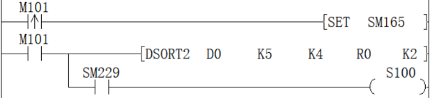
SORT2/16-bit data sorting
SORT2(P)
Sort the data rows in ascending or descending order based on the group data in column (N3), and store them in (D), based on the BIN 16-bit data table (sorting source) of (N1×N2) points specified in (S) In the BIN 16-bit data table (after sorting) of the specified (N1×N2) points.
-[SORT2 (S) (N1) (N2) (D) (N3)]
Content, range and data type
| Parameter | Content | Range | Data type | Data type (label) |
| (S) | The start device number storing the data table | - | Signed BIN 16 bit | ANY16 |
| (N1) | Number of data (rows) | 1 to 32 | Signed BIN 16 bit | ANY16 |
| (N2) | Number of group data (columns) | 1 to 6 | Signed BIN 16 bit | ANY16 |
| (D) | The start device number storing the operation result | - | Signed BIN 16 bit | ANY16 |
| (N3) | The column number of the group data (column) as the sorting basis | - | Signed BIN 16 bit | ANY16 |
Device used
| Instruction | Parameter | Devices | Offset modification | Pulse extension | ||||||||||
| KnX | KnY | KnM | KnS | T | C | D | R | SD | K | H | [D] | XXP | ||
| SORT2 | Parameter 1 | ● | ● | ● | ● | ● | ● | |||||||
| Parameter 2 | ● | ● | ● | ● | ● | ● | ● | ● | ● | ● | ● | ● | ||
| Parameter 3 | ● | ● | ● | ● | ● | ● | ● | ● | ● | ● | ● | ● | ||
| Parameter 4 | ● | ● | ● | ● | ● | ● | ||||||||
| Parameter 5 | ● | ● | ● | ● | ● | ● | ● | ● | ● | ● | ● | ● | ||
Features
Sort the data rows in ascending or descending order based on the group data in column (N3) and store them in (D) (N1×N2) point specified in the BIN 16-bit data table (after sorting).
Take (N1)=K3, (N2)=K4 in the sort source as an example, the data table structure is as follows. In the case of a sorted data table, (S) should be replaced with (D).
| When the number of groups (N2) (N2) = K4 | |||||
| Column NO.1 | Column NO.2 | Column NO.3 | Column NO.4 | ||
| Management number | Height | Weight | Age | ||
| When the number of data (N1)=3 | Line NO.1 | (S) | (S)+1 | (S) +2 | (S) +3 |
| Line NO.2 | (S) +4 | (S) +5 | (S) +6 | (S) +7 | |
| Line NO.3 | (S) +8 | (S) +9 | (S) +10 | (S) +100 | |
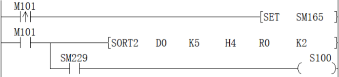
Sequence is set by the ON/OFF status of SM165
| Sort order setting instruction | |
| SM165=ON | Descending |
| SM165=OFF | Ascending |
Data alignment starts when instruction input is ON, data alignment ends after (N1) scan, instruction execution end flag SM229 is set to ON.
According to the source data sorted as follows, an example of the operation is shown below. In addition, by putting serial numbers such as management numbers in the first column in advance, the original row number can be judged based on the content, which is very convenient.
| When the number of groups (N2) (N2) = K4 | |||||
| Column NO.1 | Column NO.2 | Column NO.3 | Column NO.4 | ||
| Management number | Height | Weight | Age | ||
| When the number of data (N1) = 5 | Line NO.1 | (S) | (S)+1 | (S) +2 | (S) +3 |
| 1 | 150 | 45 | 20 | ||
| Line NO.2 | (S) +4 | (S) +5 | (S) +6 | (S) +7 | |
| 2 | 180 | 50 | 40 | ||
| Line NO.3 | (S) +8 | (S) +9 | (S) +10 | (S) +100 | |
| 3 | 160 | 70 | 30 | ||
| Line NO.4 | (S) +12 | (S) +13 | (S) +14 | (S) +15 | |
| 4 | 100 | 20 | 8 | ||
| Line NO.5 | (S) +16 | (S) +17 | (S) +18 | (S) +19 | |
| 5 | 150 | 50 | 45 | ||
Press (N3)=K2 (column number 2) to execute the sorting result (SM165=OFF in the case of ascending order)
| When the number of groups (N2) (N2) = K4 | |||||
| Column NO.1 | Column NO.2 | Column NO.3 | Column NO.4 | ||
| Management number | Height | Weight | Age | ||
| When the number of data (N1) = 5 | Line NO.1 | (D) | (D) +1 | (D) +2 | (D) +3 |
| 4 | 100 | 20 | 8 | ||
| Line NO.2 | (D) +4 | (D) +5 | (D) +6 | (D) +7 | |
| 1 | 150 | 45 | 20 | ||
| Line NO.3 | (D) +8 | (D) +9 | (D) +10 | (D) +100 | |
| 5 | 150 | 50 | 45 | ||
| Line NO.4 | (D) +12 | (D) +13 | (D) +14 | (D) +15 | |
| 3 | 160 | 70 | 30 | ||
| Line NO.5 | (D) +16 | (D) +17 | (D) +18 | (D) +19 | |
| 2 | 180 | 50 | 40 | ||
Press (N3)=K3 (column number 3) to execute the sorting result (SM165=ON in the case of ascending order)
| When the number of groups (N2) (N2) = K4 | |||||
| Column NO.1 | Column NO.2 | Column NO.3 | Column NO.4 | ||
| Management number | Height | Weight | Age | ||
| When the number of data (N1) = 5 | Line NO.1 | (D) | (D) +1 | (D) +2 | (D) +3 |
| 3 | 160 | 70 | 30 | ||
| Line NO.2 | (D) +4 | (D) +5 | (D) +6 | (D) +7 | |
| 2 | 180 | 50 | 40 | ||
| Line NO.3 | (D) +8 | (D) +9 | (D) +10 | (D) +100 | |
| 5 | 150 | 50 | 45 | ||
| Line NO.4 | (D) +12 | (D) +13 | (D) +14 | (D) +15 | |
| 1 | 150 | 45 | 20 | ||
| Line NO.5 | (D) +16 | (D) +17 | (D) +18 | (D) +19 | |
| 4 | 100 | 20 | 8 | ||
✎Note: Do not change the operand and data content during operation.
When executing again, the instruction input should be turned OFF once.
The SORT2 instruction can only be written in the program to drive 2 at most.
When the same device is specified in (S) and (D), the source data is rewritten to the sorted data order. Please pay special attention not to change the content of (S) before the end of execution.
Do not overlap the source data and the sorted data.
Error code
| Error code | Content |
| 4084H | When the value specified in (N1) exceeds the range of 1 to 32 |
| When the value specified in (N2) exceeds the range of 1 to 6 | |
| When the value specified in (N3) exceeds the range of 1 to n2 | |
| 4085H | When the device specified in read application instruction (S), (D), (N1), (N2 )and (N3) exceeds the corresponding device range |
| 4086H | When the device specified in the write application instruction (D) exceeds the corresponding device range |
| 4089H | The number of application instructions exceeded the limit. |
Example
Refer to the function description example.
DSORT2/32-bit data sorting
DSORT2(P)
Sort the data rows in ascending or descending order based on the group data of column (N3) in the BIN 32-bit data table (sorting source) of (N1×N2) points specified in (S) and store them in (D) The specified (N1×N2) point BIN 32-bit data table (after sorting).
-[DSORT2 (S) (N1) (N2) (D) (N3)]
Content, range and data type
| Parameter | Content | Range | Data type | Data type (label) |
| (S) | The start device number storing the data table | - | Signed BIN 32 bit | ANY32 |
| (N1) | Number of data (rows) | 1 to 32 | Signed BIN 32 bit | ANY32 |
| (N2) | Number of group data (columns) | 1 to 6 | Signed BIN 32 bit | ANY32 |
| (D) | The start device number storing the operation result | - | Signed BIN 32 bit | ANY32 |
| (N3) | The column number of the group data (column) as the sorting basis | - | Signed BIN 32 bit | ANY32 |
Device used
| Instruction | Parameter | Devices | Offset modification | Pulse extension | ||||||||||||
| KnX | KnY | KnM | KnS | T | C | D | R | SD | LC | HSC | K | H | [D] | XXP | ||
| DSORT2 | Parameter 1 | ● | ● | ● | ● | ● | ● | ● | ● | |||||||
| Parameter 2 | ● | ● | ● | ● | ● | ● | ● | ● | ● | ● | ● | ● | ● | ● | ||
| Parameter 3 | ● | ● | ● | ● | ● | ● | ● | ● | ● | ● | ● | ● | ● | ● | ||
| Parameter 4 | ● | ● | ● | ● | ● | ● | ● | ● | ||||||||
| Parameter 5 | ● | ● | ● | ● | ● | ● | ● | ● | ● | ● | ● | ● | ● | ● | ||
Features
Sort the data rows in ascending or descending order based on the group data in the (N3) column of the (N1×N2) point BIN 32-bit data table (sorting source) specified in (S), and store to (d) (N1×N2) specified in the BIN 32-bit data table (after sorting).
Take (N1)=K3, (N2)=K4 in the sort source as an example, the data table structure is as follows. In the case of a sorted data table, (S) should be replaced with (D).
| When the number of groups (N2) (N2) = K4 | |||||
| Column NO.1 | Column NO.2 | Column NO.3 | Column NO.4 | ||
| Management number | Height | Weight | Age | ||
| When the number of data (N1)=3 | Line NO.1 | (S)+1, (S) | (S)+3, (S)+2 | (S)+5, (S)+4 | (S) +7, (S) +6 |
| Line NO.2 | (S) +9, (S) +8 | (S)+11, (S)+10 | (S) +13, (S) +12 | (S) +15, (S) +14 | |
| Line NO.3 | (S) +17, (S) +16 | (S) +19, (S) +18 | (S) +21, (S) +20 | (S) +23, (S) +22 | |
Sequence is set by the ON/OFF status of SM165
| Sort order setting instructions | |
| SM165=ON | Descending |
| SM165=OFF | Ascending |
Data alignment starts when instruction input is ON, data alignment ends after (n1) scan, instruction execution end flag SM229 is set to ON.
According to the source data sorted as follows, an example of the operation is shown below. In addition, by putting serial numbers such as management numbers in the first column in advance, the original row number can be judged based on the content, which is very convenient.
| When the number of groups (N2) (N2) = K4 | |||||
| Column NO.1 | Column NO.2 | Column NO.3 | Column NO.4 | ||
| Management number | height | body weight | age | ||
| When the number of data (N1) = 5 | Line NO.1 | (S)+1, (S) | (S)+3, (S)+2 | (S)+5, (S)+4 | (S) +7, (S) +6 |
| 1 | 150 | 45 | 20 | ||
| Line NO.2 | (S) +9, (S) +8 | (S)+11, (S)+10 | (S) +13, (S) +12 | (S) +15, (S) +14 | |
| 2 | 180 | 50 | 40 | ||
| Line NO.3 | (S) +17, (S) +16 | (S) +19, (S) +18 | (S) +21, (S) +20 | (S) +23, (S) +22 | |
| 3 | 160 | 70 | 30 | ||
| Line NO.4 | (S) +25, (S) +24 | (S) +27, (S) +26 | (S) +29, (S) +28 | (S) +31, (S) +30 | |
| 4 | 100 | 20 | 8 | ||
| Line NO.5 | (S) +33, (S) +32 | (S) +35, (S) +34 | (S) +37, (S) +36 | (S) +39, (S) +38 | |
| 5 | 150 | 50 | 45 | ||
Press (N3)=K2 (column NO.2) to execute the sorting result (SM165=OFF in the case of ascending order)
| When the number of groups (N2) (N2) = K4 | |||||
| Column NO.1 | Column NO.2 | Column NO.3 | Column NO.4 | ||
| Management number | height | body weight | age | ||
| When the number of data (N1) = 5 | Line NO.1 | (S)+1, (S) | (S)+3, (S)+2 | (S)+5, (S)+4 | (S) +7, (S) +6 |
| 4 | 100 | 20 | 8 | ||
| Line NO.2 | (S) +9, (S) +8 | (S)+11, (S)+10 | (S) +13, (S) +12 | (S) +15, (S) +14 | |
| 1 | 150 | 45 | 20 | ||
| Line NO.3 | (S) +17, (S) +16 | (S) +19, (S) +18 | (S) +21, (S) +20 | (S) +23, (S) +22 | |
| 5 | 150 | 50 | 45 | ||
| Line NO.4 | (S) +25, (S) +24 | (S) +27, (S) +26 | (S) +29, (S) +28 | (S) +31, (S) +30 | |
| 3 | 160 | 70 | 30 | ||
| Line NO.5 | (S) +33, (S) +32 | (S) +35, (S) +34 | (S) +37, (S) +36 | (S) +39, (S) +38 | |
| 2 | 180 | 50 | 40 | ||
Press (N3)=K3 (column NO.3) to execute the sorting result (SM165=ON in the case of ascending order)
| When the number of groups (N2) (N2) = K4 | |||||
| Column NO.1 | Column NO.2 | Column NO.3 | Column NO.4 | ||
| Management number | height | body weight | age | ||
| When the number of data (N1) = 5 | Line NO.1 | (S)+1, (S) | (S)+3, (S)+2 | (S)+5, (S)+4 | (S) +7, (S) +6 |
| 3 | 160 | 70 | 30 | ||
| Line NO.2 | (S) +9, (S) +8 | (S)+11, (S)+10 | (S) +13, (S) +12 | (S) +15, (S) +14 | |
| 2 | 180 | 50 | 40 | ||
| Line NO.3 | (S) +17, (S) +16 | (S) +19, (S) +18 | (S) +21, (S) +20 | (S) +23, (S) +22 | |
| 5 | 150 | 50 | 45 | ||
| Line NO.4 | (S) +25, (S) +24 | (S) +27, (S) +26 | (S) +29, (S) +28 | (S) +31, (S) +30 | |
| 1 | 150 | 45 | 20 | ||
| Line NO.5 | (S) +33, (S) +32 | (S) +35, (S) +34 | (S) +37, (S) +36 | (S) +39, (S) +38 | |
| 4 | 100 | 20 | 8 | ||
✎Note: Do not change the operand and data content during operation.
When executing again, the instruction input should be turned OFF once.
The SORT2 instruction can only be written twice in the program.
When the same device is specified in (S) and (D), the source data is rewritten to the sorted data order. Please pay special attention not to change the content of (S) before the end of execution.
Do not overlap the source data and the sorted data.
Error code
| Error code | Content |
| 4084H | When the value specified in (N1) exceeds the range of 1 to 32 |
| When the value specified in (N2) exceeds the range of 1 to 6 | |
| When the value specified in (N3) exceeds the range of 1 to n2 | |
| 4085H | When the device specified in read application instruction (S), (D), (N1), (N2 )and (N3) exceeds the corresponding device range |
| 4086H | When the device specified in the write application instruction (D) exceeds the corresponding device range |
| 4089H | The number of application instructions exceeded the limit. |
Example
Refer to the function description example.
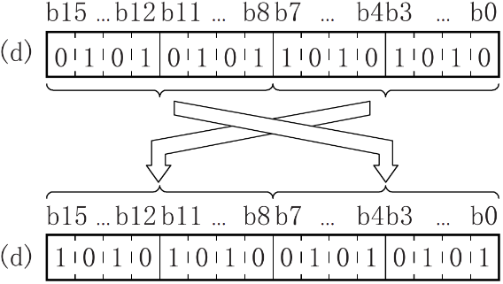
SWAP/16-bit data high and low byte swap
SWAP(P)
Swap the high and low 8-bit value of the device specified in (D).
-[SWAP (D)]
Content, range and data type
| Parameter | Content | Range | Data type | Data type (label) |
| (D) | Word device with high and low byte swap | - | Signed BIN 16 bit | ANY16 |
Device used
| Instruction | Parameter | Devices | Offset modification | Pulse extension | |||||||
| KnY | KnM | KnS | T | C | D | R | SD | [D] | XXP | ||
| SWAP | Parameter 1 | ● | ● | ● | ● | ● | ● | ● | ● | ● | ● |
Features
Convert the high and low 8-bit value of the device specified in (D).
Error code
| Error code | Content |
| 4085H | When the device specified in the read application instruction (D) exceeds the corresponding device range |
| 4086H | When the device specified in the write application instruction (D) exceeds the corresponding device range |
Example
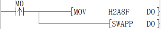
When the rising edge of M0 is triggered, swap the low 8 bits and high 8 bits of D0 to get H8F2A.
DSWAP/32-bit data high and low byte swap
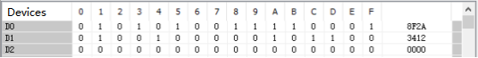
DSWAP(P)
The devices specified in (D) and (D)+1 will be converted to the high and low 8-bit values respectively.
-[DSWAP (D)]
Content, range and data type
| Parameter | Content | Range | Data type | Data type (label) |
| (D) | Word device with high and low byte swap | - | Signed BIN 32 bit | ANY32 |
Device used
| Instruction | Parameter | Devices | Offset modification | Pulse extension | |||||||||
| KnY | KnM | KnS | T | C | D | R | SD | LC | HSC | [D] | XXP | ||
| DSWAP | Parameter 1 | ● | ● | ● | ● | ● | ● | ● | ● | ● | ● | ● | ● |
Features
The devices specified in (D) and (D)+1 will be converted to the upper and lower 8-bit values respectively.
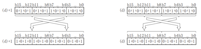
✎Note: If continuous execution instructions are used, conversion will be performed every scan cycle.
Error code
| Error code | Content |
| 4085H | When the device specified in the read application instruction (D) exceeds the corresponding device range |
| 4086H | When the device specified in the write application instruction (D) exceeds the corresponding device range |
Example
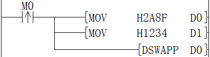
When the rising edge of M0 is triggered, the low 8 bits and the high 8 bits of D0 and D1 are swapped, and D0=H8F2A, D1=H3412 are obtained.
BTOW/Byte unit data merge
BTOW(P)
Combine the low 8 bits of (N) bytes of BIN 16-bit data stored after the device number specified in (S) into word units and store it after the device number specified in (D).
-[BTOW (S) (D) (N)]
Content, range and data type
| Parameter | Content | Range | Data type | Data type (label) |
| (S) | The start device that stores the data merging in byte units | - | Signed BIN 16 bit | ANY16 |
| (D) | The start device that stores the result of merging in byte units | - | Signed BIN 16 bit | ANY16 |
| (N) | Number of byte data merged | 0-32767 | Signed BIN 16 bit | ANY16 |
Device used
| Instruction | Parameter | Devices | Offset modification | Pulse extension | ||||||||||
| KnX | KnY | KnM | KnS | T | C | D | R | SD | K | H | [D] | XXP | ||
| BTOW | Parameter 1 | ● | ● | ● | ● | ● | ● | ● | ||||||
| Parameter 2 | ● | ● | ● | ● | ● | ● | ● | |||||||
| Parameter 3 | ● | ● | ● | ● | ● | ● | ● | ● | ● | ● | ● | ● | ● | |
Features
After the device number specified in (s), the lower 8 bits of the 16-bit BIN data stored in (n) bytes are combined into word units and stored in the device number specified in (d) or later.
The upper 8 bits of (n) word data stored after the device number specified in (s) will be ignored. In addition, when (n) is an odd number, 0 is stored in the upper 8 bits of the device storing the (n)th byte of data.
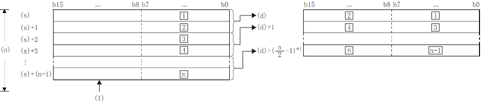
£: the £th byte data;
(1): Ignore the high byte
*1: Carry below the decimal point.
Example
When (N)=5, the data up to the lower 8 bits of (S)+(S)+4 is stored in (D)+(D)+2.
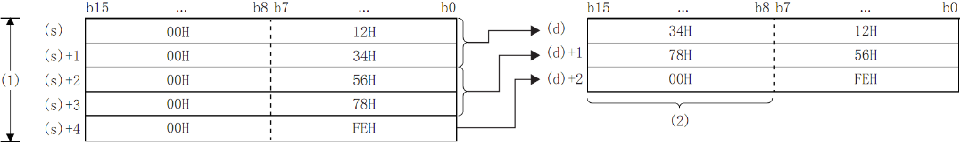
(1): When (N)=5
(2): Change to 00H
By setting the number of bytes in (N), the range of byte data specified in (S) and the range of the device storing the combined data specified in (D) will be automatically determined.
When the number of bytes specified in (N) is 0, no processing is performed.
The upper 8 bits of the byte data storage device specified in (S) will be ignored, and the lower 8 bits will be the target.
Example
When the low 8 bits of D11 to D16 is stored in D12 to D14.
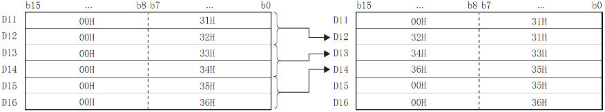
Even if the device range storing the data before merging overlaps the device rangestoring merged data, it will be handled as normal.
| Device range storing the data before merging | Device range for storing merged data |
| (S)+0 to (S)+(N)-1 | (D) to (D) + (N/2-1) |
Error code
| Error code | Content |
| 4084H | The value specified in (N) exceed range of 0 to 32767 |
| 4085H | When the device specified in the write application instruction (S),(D) and (N) exceeds the corresponding device range |
Example
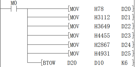
When M0 is ON, the data of D20 to D25 is separated according to byte units, and then stored in D10 to D12.
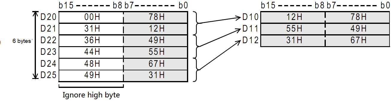
WTOB/Byte unit data separation
WTOB(P)
After separating the BIN 16-bit data stored after the device number specified in (S) into (N) bytes, store it after the device number specified in (D).
-[WTOB (S) (D) (N)]
Content, range and data type
| Parameter | Content | Range | Data type | Data type (label) |
| (S) | The start device that stores the data separation in byte unit | - | Signed BIN 16 bit | ANY16 |
| (D) | The start device that stores the result of separation in byte unit | - | Signed BIN 16 bit | ANY16 |
| (N) | Number of byte data separated | 0-32767 | Signed BIN 16 bit | ANY16 |
Device used
| Instruction | Parameter | Devices | Offset modification | Pulse extension | ||||||
| T | C | D | R | SD | K | H | [D] | XXP | ||
| WTOB | Parameter 1 | ● | ● | ● | ● | ● | ● | ● | ||
| Parameter 2 | ● | ● | ● | ● | ● | ● | ● | |||
| Parameter 3 | ● | ● | ● | ● | ● | ● | ● | |||
Features
After separating the BIN 16-bit data stored after the device number specified in (S) into (N) bytes, store it after the device number specified in (D).
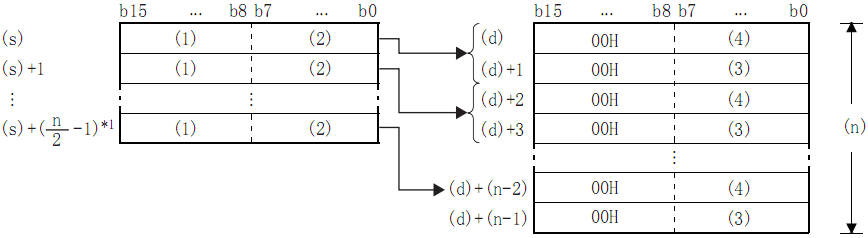
- High byte;
- Low byte;
- High byte data;
- Low byte data;
- *1: Carry below the decimal point.
Example
In the case of (N)=5, store the data up to the lower 8 bits of (S) to (S)+2 in (D) to (D)+4:
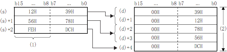
- (N)=5 is ignored.
- (N)=5.
By setting the number of bytes in (N), the range of BIN 16-bit data specified in (S) and the range of the device storing the byte data specified in (D) will be automatically determined.
When the number of bytes specified in (N) is 0, no processing is performed.
00H is automatically stored in the upper 8 bits of the byte data storage device specified in (D).
Example
When D12 to D14 is stored in the low 8 bits of D11 to D16
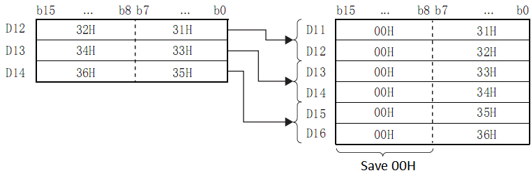
Even if the device range storing the data before merging overlaps the device rangestoring merged data, it will be handled as normal.
| Device range storing the data before merging | Device range storing separated data |
| (S) to (S) + (N/2-1) | (D)+0 to (D)+(N)-1 |
Error code
| Error code | Content |
| 4084H | The value specified by (N) exceed the range of 0 to 32767 |
| 4085H | When the device specified in read application instruction (S) and (N) exceeds the corresponding device range |
| 4086H | When the device specified in the write application instruction (D) exceeds the corresponding device range |
Example
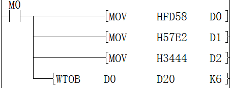
When M0 is ON, the data of D10 to D12 are separated according to byte units, and then stored in D20 to D25.
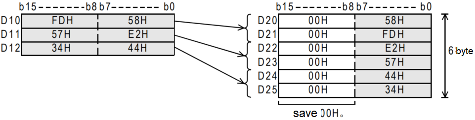
DIS/4-bit separation of 16-bit data
DIS(P)
Store the data of the low (N) bits (1 bit of 4 bits) of the BIN 16-bit data specified in (S) into the low 4-bit of the (N) point starting from the device specified in (D).
-[DIS (S) (D) (N)]
Content, range and data type
| Parameter | Content | Range | Data type | Data type (label) |
| (S) | The start device storing the data before separation | - | Signed BIN 16 bit | ANY16 |
| (D) | The start device storing separated data | - | Signed BIN 16 bit | ANY16 |
| (N) | Separation number (0 means no processing) | 0-4 | Signed BIN 16 bit | ANY16 |
Device used
| Instruction | Parameter | Devices | Offset modification | Pulse extension | ||||||||||
| KnX | KnY | KnM | KnS | T | C | D | R | SD | K | H | [D] | XXP | ||
| DIS | Parameter 1 | ● | ● | ● | ● | ● | ● | ● | ● | ● | ● | ● | ● | ● |
| Parameter 2 | ● | ● | ● | ● | ● | ● | ● | |||||||
| Parameter 3 | ● | ● | ● | ● | ● | ● | ● | ● | ● | ● | ● | ● | ● | |
Features
Store the low-(N) bit (1 bits of 4 bits) of the BIN 16-bit data specified in (S) in the low 4-bit of the (N) point starting from the device specified in (D).
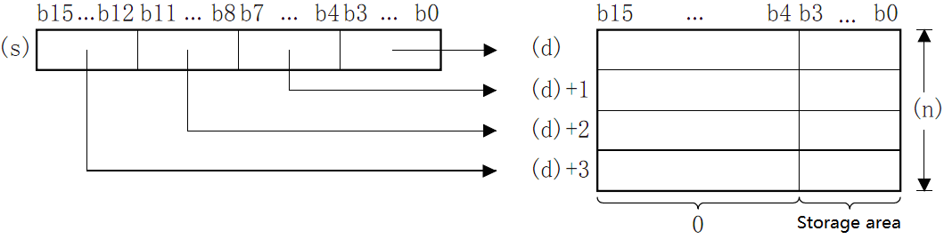
The hig-12 bit of the point (N) starting from the device specified in (S) will become 0.
When (N)=0, it will become no processing, and the content of point (N) starting from the device of (D) will not change.
Error code
| Error code | Content |
| 4084H | The data in (N) exceed the range of 0 to 4 |
| 4085H | When the device specified in read application instruction (S) and (N) exceeds the corresponding device range |
| 4086H | When the device specified in the write application instruction (D) exceeds the corresponding device range |
Example
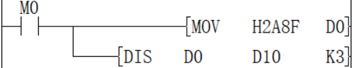
When M0 is ON, D0 is separated every 4 bits and stored in D10 to D12. The result is D10 = HF, D11 = H8, D12 = HA.
UNI/4-bit combination of 16-bit data
UNI(P)
Combine the low 4 bits of the BIN 16-bit data of point (N) starting from the device specified in (S) into the BIN 16-bit device specified in (D).
-[UNI (S) (D) (N)]
Content, range and data type
| Parameter | Content | Range | Data type | Data type (label) |
| (S) | The start device storing the data before merging | - | Signed BIN 16 bit | ANY16 |
| (D) | The start device storing the merged data | - | Signed BIN 16 bit | ANY16 |
| (N) | Number of merger | 0-4 | Signed BIN 16 bit | ANY16 |
Device used
| Instruction | Parameter | Devices | Offset modification | Pulse extension | ||||||||||
| KnX | KnY | KnM | KnS | T | C | D | R | SD | K | H | [D] | XXP | ||
| UNI | Parameter 1 | ● | ● | ● | ● | ● | ● | ● | ||||||
| Parameter 2 | ● | ● | ● | ● | ● | ● | ● | ● | ● | ● | ||||
| Parameter 3 | ● | ● | ● | ● | ● | ● | ● | ● | ● | ● | ● | ● | ● | |
Features
Combine the low 4 bits of the BIN 16-bit data at point (N) starting from the device specified in (S) into the BIN 16-bit device specified in (D).
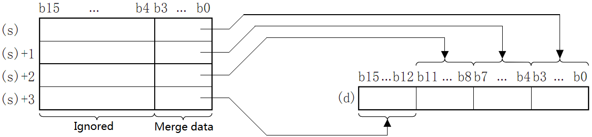
The high (4-N) bits of the device specified in (D) will become 0.
When (N)=0, it will become no processing, and the content of the device in (D) will not change.
Error code
| Code | Content |
| 4084H | The data in (N) exceed the range of 0 to 4 |
| 4085H | When the device specified in read application instruction (S) and (N) exceeds the corresponding device range |
| 4086H | When the device specified in the write application instruction (D) exceeds the corresponding device range |
Example
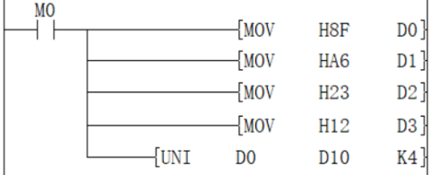
When M0 is ON, the low 4 bits of D0 to D3 are combined and stored in D10, the value is H236F.
ZRST/Data batch reset
ZRST(P)
Perform a batch reset between the devices specified in (d1) and (d2) of the same type. It is used when interrupting operation, performing initial operation, or resetting control data.
-[ZRST (d1) (d2)]
Content, range and data type
| Parameter | Content | Range | Data type | Data type (label) |
| (d1) | The start bit or word device number of batch reset | - | Bit/Signed BIN 16 bit | ANY_ELEMENTARY |
| (d2) | The final bit or word device number of batch reset | - | Bit/Signed BIN 16 bit | ANY_ELEMENTARY |
Device used
| Instruction | Parameter | Devices | Offset modification | Pulse extension | ||||||||||||||
| Y | M | S | SM | KnX | KnY | KnM | KnS | T | C | D | R | SD | LC | HSC | [D] | XXP | ||
| ZRST | Parameter 1 | ● | ● | ● | ● | ● | ● | ● | ● | ● | ● | ● | ● | ● | ● | ● | ● | ● |
| Parameter 2 | ● | ● | ● | ● | ● | ● | ● | ● | ● | ● | ● | ● | ● | ● | ● | ● | ● | |
Features
Perform batch reset between the devices specified in (d1) and (d2) of the same type.
When (d1) and (d2) are bit devices, write OFF (reset) in the entire device range of (d1) to (d2).
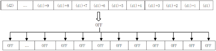
When (d1) and (d2) are word devices, write K0 in the entire device range of (d1) to (d2).
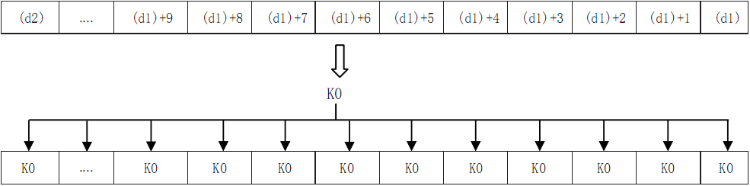
As a separate reset instruction for the device, the RST instruction can be used for bit devices or word devices.
Reset M0
Reset D0
Reset the current value of T0
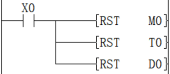
The batch write instruction of constant (for example: K0) has FMOV (P) instruction, which can write 0 to word devices (including bit device specification).
Write K0 in D0 to D99.
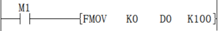
✎Note: Please specify the same type number for (d1) and (d2), and make (d1) number <(d2) number. When (d1) number ≥ (d2) number, only 1 point will be reset for the device specified in (d1).
ZRST(P) instruction is a 16-bit instruction, which can specify (LC) and (HSC) devices for (d1) and (d2).
Error code
| Error code | Content |
| 4084H | When the device type specified in (d1) is different from the device type specified in (d2). |
| 4085H | When the device specified in the read application instruction (d1) and (d2) exceeds the corresponding device range |
| 4086H | When the device specified in the write application instruction (d1) exceeds the corresponding device range |
Example
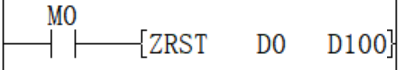
The function of this Circuit program instruction is to set the value of the D0 to D100 device to 0.
ZSET/Data batch set
ZSET(P)
Perform a batch set between the devices specified in (d1) and (d2) of the same type.
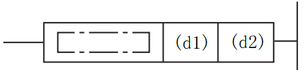
Content, range and data type
| Parameter | Content | Range | Data type | Data type(label) |
| (d1) | The start bit device number of batch set | - | Bit | ANY_BOOL |
| (d2) | The final bit device number of batch set | - | Bit | ANY_BOOL |
Device used
| Instruction | Parameter | Devices | Offset modification | ||||
| Y | M | S | SM | D.b | [D] | ||
| ZSET | Parameter 1 | ● | ● | ● | ● | ● | ● |
| Parameter 2 | ● | ● | ● | ● | ● | ● | |
Features
·Perform a batch set between the devices specified in (d1) and (d2) of the same type.
·Write ON (set) in the entire device range of (d1) to (d2)
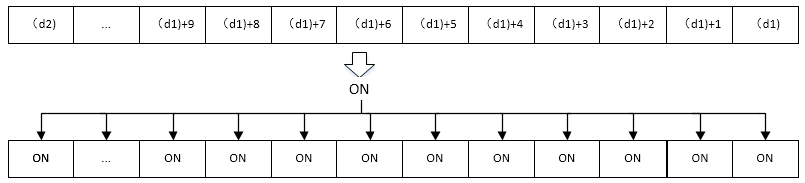
·As a separate set instruction for the device, the SET instruction can be used for bit devices.
Set M1
Set Y1
Set S1
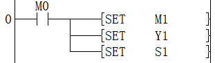
✎Note: Please specify the same type number for (d1) and (d2), and make (d1) number <(d2) number. When (d1) number ≥ (d2) number, only 1 point will be set for the device specified in (d1).
Error code
| Error code | Content |
| 4084H | When the device type specified in (d1) is different from the device type specified in (d2). |
| 4085H | When the device specified in the read application instruction (d1) and (d2) exceeds the corresponding device range |
| 4086H | When the device specified in the write application instruction (d1) exceeds the corresponding device range |
| 4087H | When the device type specified in (d1) and (d2) are not bit device. |
Example
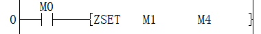
The function of this LAD instruction is to set the value of the M1 to M4 device to ON.
CRC/cyclic redundancy check instruction
CRC(P)
Calculate the CRC (Cyclic Redundancy Check) value, which is one of the error checking methods used in communications. In addition to CRC, error checking methods include parity and
Sum check (checksum), calculate horizontal parity check value and sum check value can use CCD(P) instruction . And this instruction is used in the generator polynomial that generates the CRC value (CRC-16)
"X 16 +X 15 +X 2 +1".
-[CRC(P) (S) (D) (N)]
Content, range and data type
| Parameter | Content | Range | Data type | Data type (label) |
| (S) | The device start number storing the data of CRC value generated objects | - | Signed BIN16 | ANY16 |
| (D) | The destination device number of the generated CRC value | - | Signed BIN16 | ANY16 |
| (N) | The number of 8-bit data (bytes) for calculating the CRC value or the number of the device storing the number of data | 1 to 256 | Unsigned BIN16 | ANY16_U |
Device used
| Instruction | Parameter | Devices | Offset modification | Pulse extension | ||||||||||
| KnX | KnY | KnM | KnS | T | C | D | R | SD | K | H | [D] | XXP | ||
| CRC | Parameter 1 | ● | ● | ● | ● | ● | ● | ● | ● | ● | ● | ● | ||
| Parameter 2 | ● | ● | ● | ● | ● | ● | ● | ● | ● | ● | ||||
| Parameter 3 | ● | ● | ● | ● | ● | ● | ● | ● | ● | ● | ● | ● | ||
Features
Start with the device specified in (S), generate the CRC value of 8-bit data (byte unit) at (N) point, and store it in (D).
The mode used by this instruction in calculation includes 16-bit conversion mode and 8-bit conversion mode. For the operation of each mode, please refer to the following content.
1. 16-bit conversion mode (when SM161=OFF)
Calculate the upper 8 bits (byte) and lower 8 bits (byte) of the (S) device. The result is stored in 16 bits of 1 point of the device specified in (D). In the case of the following program, perform the conversion as shown below.
| Example (s)=D100, (d)=D0, (n)=6 | |||||
| Devices | Content of object data | ||||
| 8-bit | 16-bit | ||||
| CRC value generation target data storage destination | (s) | Low byte | D100 low | 01H | 0301H |
| High byte | D100 high | 03H | |||
| (s)+1 | Low byte | D101 low | 03H | 0203H | |
| High byte | D101 high | 02H | |||
| (s)+2 | Low byte | D102 low | 00H | 1400H | |
| High byte | D102 high | 14H | |||
| ... | | | |||
| (S)+(N)/2-1 | Low byte | | |||
| High byte | |||||
| CRC value storage target | (d) | Low byte | D0 low | E4H | 41E4H |
| High byte | D0 high | 41H | |||
2. 8-bit conversion mode (when SM8161=ON)
In 8-bit conversion mode, only the lower 8 bits (lower byte) of the (s) device are operated on. As a result, 2 points are used starting from the device specified in (d), the lower 8 bits (bytes) are stored in (d), and the upper 8 bits (bytes) are stored in (d)+1.
In the case of the following program, perform the conversion as shown below.
| Example) (s)=D100, (d)=D0, (n)=6 | ||||
| Devices | Content of object data | |||
| CRC value generation target data storage destination | (s) | Low byte | D100 low | 01H |
| (s)+1 | Low byte | D101 low | 03H | |
| (s)+2 | Low byte | D102 low | 03H | |
| (s)+3 | Low byte | D103 low | 02H | |
| (s)+4 | Low byte | D104 low | 00H | |
| (s)+5 | Low byte | D105 low | 14H | |
| ... | | |||
| (S)+(N)-1 | Low byte | | ||
| CRC value storage target | (d) | Low byte | D0 | E4H |
| (d)+1 | Low byte | D1 | 41H | |
In the CRC(P) instruction, the generator polynomial of the CRC value (CRC-16) uses "X16+X15+X2+1", but there are also many standardized generator polynomials for the CRC value. If the generator polynomial is different, it will become a completely different CRC value, which should be noted. The main CRC value generator polynomials are shown below.
| Name | Generator polynomial |
| CRC-12 | X12+X11+X3+X2+X+1 |
| CRC-16 | X16+X15+X2+1 |
| CRC-32 | X32+X26+X23+X22+X16+X12+X11+X10+X8+X7+X5+X4+X2+X+1 |
| CRC-CCITT | X16+X12+X5+1 |
✎Note:
When (s1) use KnX, KnY, KnM, KnS, n must be specified as 4.
Error code
| Error code | Content |
| 4084H | The range of (N) exceeds 1 to 256 |
| 4085H | The data address of (S) to be converted exceeds the device range |
| 4086H | The (D) write address exceeds the device range |
| 4087H | Unsupported device type is used by (S) and (D) |
Example
1. 16-bit conversion mode
2. 8-bit conversion mode