12
Contact comparison instruction
Signed 16-bit contact comparison instruction
LD £, AND £, OR £
The BIN 16-bit data of the device specified in (s1) and the BIN 16-bit data of the device specified in (s2) are compared by normal open contact processing.
LD£: Normally open contact comparison instruction
AND£: Normally open contact series connection comparison instruction
OR£: Normally open contact parallel connection comparison instruction
Ladder diagram

(You can enter "=", "<>", ">", "<", ">=", "<=" in "£")
Content, range and data type
| Parameter | Content | Range | Data type | Data type (label) |
| (s1) | Comparison data or device storing comparison data | -32768 to 32767 | Signed BIN 16 bit | ANY16_S |
| (s2) | Comparison data or device storing comparison data | -32768 to 32767 | Signed BIN 16 bit | ANY16_S |
Device used
| Instruction | Parameter | Devices | Offset modification | Pulse extension | ||||||||||
| KnX | KnY | KnM | KnS | T | C | D | R | SD | K | H | [D] | XXP | ||
| LD= | s1, s2 | ● | ● | ● | ● | ● | ● | ● | ● | ● | ● | ● | ● | |
| LD> | s1, s2 | ● | ● | ● | ● | ● | ● | ● | ● | ● | ● | ● | ● | |
| LD< | s1, s2 | ● | ● | ● | ● | ● | ● | ● | ● | ● | ● | ● | ● | |
| LD>= | s1, s2 | ● | ● | ● | ● | ● | ● | ● | ● | ● | ● | ● | ● | |
| LD<= | s1, s2 | ● | ● | ● | ● | ● | ● | ● | ● | ● | ● | ● | ● | |
| LD<> | s1, s2 | ● | ● | ● | ● | ● | ● | ● | ● | ● | ● | ● | ● | |
| AND= | s1, s2 | ● | ● | ● | ● | ● | ● | ● | ● | ● | ● | ● | ● | |
| AND> | s1, s2 | ● | ● | ● | ● | ● | ● | ● | ● | ● | ● | ● | ● | |
| AND< | s1, s2 | ● | ● | ● | ● | ● | ● | ● | ● | ● | ● | ● | ● | |
| AND>= | s1, s2 | ● | ● | ● | ● | ● | ● | ● | ● | ● | ● | ● | ● | |
| AND<= | s1, s2 | ● | ● | ● | ● | ● | ● | ● | ● | ● | ● | ● | ● | |
| AND<> | s1, s2 | ● | ● | ● | ● | ● | ● | ● | ● | ● | ● | ● | ● | |
| OR= | s1, s2 | ● | ● | ● | ● | ● | ● | ● | ● | ● | ● | ● | ● | |
| OR> | s1, s2 | ● | ● | ● | ● | ● | ● | ● | ● | ● | ● | ● | ● | |
| OR< | s1, s2 | ● | ● | ● | ● | ● | ● | ● | ● | ● | ● | ● | ● | |
| OR>= | s1, s2 | ● | ● | ● | ● | ● | ● | ● | ● | ● | ● | ● | ● | |
| OR<= | s1, s2 | ● | ● | ● | ● | ● | ● | ● | ● | ● | ● | ● | ● | |
| OR<> | s1, s2 | ● | ● | ● | ● | ● | ● | ● | ● | ● | ● | ● | ● | |
Features
The BIN 16-bit data of the device specified in (s1) and the BIN 16-bit data of the device specified in (s2) are compared by normal open contact processing.
The comparison operation result of each instruction is shown below.
| Instruction Sign | Condition | Comparison operation result | Instruction Sign | Condition | Comparison operation result |
| = | (s1)=(s2) | On state | = | (s1)≠(s2) | Non-conduction state |
|---|---|---|---|---|---|
| <> | (s1)≠(s2) | <> | (s1)=(s2) | ||
| > | (s1)>(s2) | > | (s1)≤(s2) | ||
| < | (s1)<(s2) | < | (s1)≥(s2) | ||
| >= | (s1)≥(s2) | >= | (s1)<(s2) | ||
| <= | (s1)≤(s2) | <= | (s1)>(s2) |
Error code
| Error code | Content |
| 4085H | (s) read address exceeds the device range |
Example
(1) LD£ instruction:

When the current value of counter C10 is 200, Y10 is set
When the content of D200 is above -29, and X1 is ON, Y11 is set
(2) AND£ instruction:

When X0 is ON, or when the current value of counter C10 is 200, Y10 is set
When X1 is OFF, and the content of data counter D0 is not -10, Y11 is set
(3) OR£ instruction:

When X1 is ON, or when the current value of counter C10 is 200, Y0 is set
When X2 and M30 are ON, or the content of register D100 is K10000 and above, M60 is set
Signed 32-bit contact comparison instruction
LDD £, ANDD £, ORD £
The BIN 32-bit data of the device specified in (s1) and the BIN 32-bit data of the device specified in (s2) are compared by normal open contact processing.
LDD£: Normally open contact comparison command
ANDD£: Normally open contact series link comparison instruction
ORD£: Normally open contact parallel link comparison instruction
Ladder diagram
“=”, “<>”, “>”, “<”, “>=”, “<=” can be input in “£”
Content, range and data type
| Parameter | Content | Range | Data type | Data type (label) |
| (s1) | Comparison data or device storing comparison data | -2147483648 to 2147483647 | Signed BIN 32 bit | ANY32_S |
| (s2) | Comparison data or device storing comparison data | -2147483648 to 2147483647 | Signed BIN 32 bit | ANY32_S |
Device used
| Instruction | Parameter | Devices | Offset modification | Pulse extension | ||||||||||||
| KnX | KnY | KnM | KnS | T | C | D | R | SD | LC | HSC | K | H | [D] | XXP | ||
| LDD= | s1, s2 | ● | ● | ● | ● | ● | ● | ● | ● | ● | ● | ● | ● | ● | ● | |
| LDD> | s1, s2 | ● | ● | ● | ● | ● | ● | ● | ● | ● | ● | ● | ● | ● | ● | |
| LDD< | s1, s2 | ● | ● | ● | ● | ● | ● | ● | ● | ● | ● | ● | ● | ● | ● | |
| LDD>= | s1, s2 | ● | ● | ● | ● | ● | ● | ● | ● | ● | ● | ● | ● | ● | ● | |
| LDD<= | s1, s2 | ● | ● | ● | ● | ● | ● | ● | ● | ● | ● | ● | ● | ● | ● | |
| LDD<> | s1, s2 | ● | ● | ● | ● | ● | ● | ● | ● | ● | ● | ● | ● | ● | ● | |
| ANDD= | s1, s2 | ● | ● | ● | ● | ● | ● | ● | ● | ● | ● | ● | ● | ● | ● | |
| ANDD> | s1, s2 | ● | ● | ● | ● | ● | ● | ● | ● | ● | ● | ● | ● | ● | ● | |
| ANDD< | s1, s2 | ● | ● | ● | ● | ● | ● | ● | ● | ● | ● | ● | ● | ● | ● | |
| ANDD>= | s1, s2 | ● | ● | ● | ● | ● | ● | ● | ● | ● | ● | ● | ● | ● | ● | |
| ANDD<= | s1, s2 | ● | ● | ● | ● | ● | ● | ● | ● | ● | ● | ● | ● | ● | ● | |
| ANDD<> | s1, s2 | ● | ● | ● | ● | ● | ● | ● | ● | ● | ● | ● | ● | ● | ● | |
| ORD= | s1, s2 | ● | ● | ● | ● | ● | ● | ● | ● | ● | ● | ● | ● | ● | ● | |
| ORD> | s1, s2 | ● | ● | ● | ● | ● | ● | ● | ● | ● | ● | ● | ● | ● | ● | |
| ORD< | s1, s2 | ● | ● | ● | ● | ● | ● | ● | ● | ● | ● | ● | ● | ● | ● | |
| ORD>= | s1, s2 | ● | ● | ● | ● | ● | ● | ● | ● | ● | ● | ● | ● | ● | ● | |
| ORD<= | s1, s2 | ● | ● | ● | ● | ● | ● | ● | ● | ● | ● | ● | ● | ● | ● | |
| ORD<> | s1, s2 | ● | ● | ● | ● | ● | ● | ● | ● | ● | ● | ● | ● | ● | ● | |
Features
The BIN 32-bit data of the device specified in (s1) and the BIN 32-bit data of the device specified in (s2) are compared by normal open contact processing.
The comparison operation result of each instruction is shown below.
| Instruction Sign | Condition | Comparison operation result | Instruction Sign | Condition | Comparison operation result |
| = | (s1)=(s2) | On state | = | (s1)≠(s2) | Non-conduction state |
|---|---|---|---|---|---|
| <> | (s1)≠(s2) | <> | (s1)=(s2) | ||
| > | (s1)>(s2) | > | (s1)≤(s2) | ||
| < | (s1)<(s2) | < | (s1)≥(s2) | ||
| >= | (s1)≥(s2) | >= | (s1)<(s2) | ||
| <= | (s1)≤(s2) | <= | (s1)>(s2) |
Error code
| Error code | Content |
| 4085H | (S) read address exceeds the device range |
Example
(1) LDD£ instruction:

When the data of LC10 is 200000, Y10 is set, otherwise Y10 is reset.
When the 32-bit data composed of D201 and D200 exceeds -5000, and X1 is ON, Y11 is turned ON.
(2) ANDD£ instruction:

When X0 is ON and the value of LC10 is 200000, Y10 is set, otherwise it is reset.
When X1 is OFF and the 32-bit data composed of D1 and D0 is not equal to K-50000, Y11 is set.
(3) ORD£ instruction:

When X1 is ON, or the data of LC10 is equal to the data of LC10 is equal to 200000, Y0 is set.
When X2 and M30 are set, or the double word data composed of D101 and D100 is greater than or equal to 100000, M60 is set.
Single precision real number contact comparison instruction
LDE £, ANDE £, ORE £
The single precision real number of the device specified in (s1) and the single precision real number of the device specified in (s2) are compared by normal open contact processing.
LDE£: Normally open contact comparison command
ANDE£: Normally open contact series link comparison instruction
ORE£: Normally open contact parallel link comparison instruction
Ladder diagram

“=”, “<>”, “>”, “<”, “>=”, “<=” can be input in “£”
Content, range and data type
| Parameter | Content | Range | Data type | Data type (label) |
| (s1) | Comparison data or the device start number storing the comparison data | 0, 2-126 ≤|(s)|< 2128 | Single precision real number | ANYREAL_32 |
| (s2) | Comparison data or the device start number storing the comparison data | 0, 2-126 ≤|(s)|< 2128 | Single precision real number | ANYREAL_32 |
Device used
| Instruction | Parameter | Devices | Offset modification | Pulse extension | |||||||
| T | C | D | R | SD | LC | HSC | E | [D] | XXP | ||
| LDE= | s1, s2 | ● | ● | ● | ● | ● | ● | ● | ● | ● | |
| LDE> | s1, s2 | ● | ● | ● | ● | ● | ● | ● | ● | ● | |
| LDE< | s1, s2 | ● | ● | ● | ● | ● | ● | ● | ● | ● | |
| LDE>= | s1, s2 | ● | ● | ● | ● | ● | ● | ● | ● | ● | |
| LDE<= | s1, s2 | ● | ● | ● | ● | ● | ● | ● | ● | ● | |
| LDE<> | s1, s2 | ● | ● | ● | ● | ● | ● | ● | ● | ● | |
| ANDE= | s1, s2 | ● | ● | ● | ● | ● | ● | ● | ● | ● | |
| ANDE> | s1, s2 | ● | ● | ● | ● | ● | ● | ● | ● | ● | |
| ANDE< | s1, s2 | ● | ● | ● | ● | ● | ● | ● | ● | ● | |
| ANDE>= | s1, s2 | ● | ● | ● | ● | ● | ● | ● | ● | ● | |
| ANDE<= | s1, s2 | ● | ● | ● | ● | ● | ● | ● | ● | ● | |
| ANDE<> | s1, s2 | ● | ● | ● | ● | ● | ● | ● | ● | ● | |
| ORE= | s1, s2 | ● | ● | ● | ● | ● | ● | ● | ● | ● | |
| ORD> | s1, s2 | ● | ● | ● | ● | ● | ● | ● | ● | ● | |
| ORE< | s1, s2 | ● | ● | ● | ● | ● | ● | ● | ● | ● | |
| ORE>= | s1, s2 | ● | ● | ● | ● | ● | ● | ● | ● | ● | |
| ORE<= | s1, s2 | ● | ● | ● | ● | ● | ● | ● | ● | ● | |
| ORE<> | s1, s2 | ● | ● | ● | ● | ● | ● | ● | ● | ● | |
Features
The single precision real number of the device specified in (s1) and the single precision real number of the device specified in (s2) are compared by normal open contact processing.
The comparison operation result of each instruction is shown below.
| Instruction Sign | Condition | Comparison operation result | Instruction Sign | Condition | Comparison operation result |
| E= | (s1)=(s2) | On state | E= | (s1)≠(s2) | Non-conduction state |
| E<> | (s1)≠(s2) | E<> | (s1)=(s2) | ||
| E> | (s1)>(s2) | E> | (s1)≤(s2) | ||
| E< | (s1)<(s2) | E< | (s1)≥(s2) | ||
| E>= | (s1)≥(s2) | E>= | (s1)<(s2) | ||
| E<= | (s1)≤(s2) | E<= | (s1)>(s2) |
Error code
| Error code | Content |
| 4084H | When the content of the specified device by (s1) and (s2) is an irregular number, a non-number, or ±∞ |
| 4085H | The read address of (s1) and (s2exceeds the device range |
Example
(1) LDE£ instruction:

When the real number input in D0 is equal to E1.23, Y10 is ON, otherwise Y10 is OFF.
When the real number in R0 is greater than or equal to the real number in LC0, Y11 is ON, otherwise it is OFF.
If the input in D0, R0, LC0 is not a real number, it will report H4084 error.
(2) ANDE£ instruction:

Only when M0 is ON and D2 real number is not equal to E1.23 and R2 real number is less than real number LC2 , Y12 is ON, otherwise all are OFF.
(3) ORE£ instruction:

When the real number of R4 is less than or equal to the real number of R15, or the real number R6 is equal to the real number R20, Y13 is ON, otherwise Y13 is OFF.
String comparison
LDS£、ANDS£、 ORS£
Compare the string stored after the device number specified in (s1) with the string stored after the device number specified in (s2).
LDS£: String comparison instruction
ANDS£: String serial connection comparison instruction
ORS£: String parallel connection comparison instruction
Ladder diagram

“=” and “<>” could be entered in “£”
Content, range and data type
| Parameter | Content | Range | Date type | Date type(label) |
| (S1) | Connection data or the device start number storing the data or the string specified directly | - | String | ANYSTRING_SINGLE |
| (S1) | Connection data or the device start number storing the data or the string specified directly | - | String | ANYSTRING_SINGLE |
Device used
| Instruction | Parameter | Devices | Offset modification | Pulse extension | ||||||||
| KnX | KnY | KnM | KnS | T | C | D | R | SD | [D] | XXP | ||
| LDS= | s1、s2 | ● | ● | ● | ● | ● | ● | ● | ● | ● | ● | |
| LDS<> | s1、s2 | ● | ● | ● | ● | ● | ● | ● | ● | ● | ● | |
| ANDS= | s1、s2 | ● | ● | ● | ● | ● | ● | ● | ● | ● | ● | |
| ANDS<> | s1、s2 | ● | ● | ● | ● | ● | ● | ● | ● | ● | ● | |
| ORS= | s1、s2 | ● | ● | ● | ● | ● | ● | ● | ● | ● | ● | |
| ORS<> | s1、s2 | ● | ● | ● | ● | ● | ● | ● | ● | ● | ● | |
Features
• Compare the string stored after the device number specified in (s1) with the string stored after the device number specified in (s2).
• The comparison operation result of each instruction is shown below.
| Instruction sign | Condition | Comparison operation result | Instruction sign | Condition | Comparison operation result |
| = | (s1)=(s2) | On stat | = | (s1)≠(s2) | Non-conduction state |
|---|---|---|---|---|---|
| <> | (s1)≠(s2) | <> | (s1)=(s2) |
Error code
| Error code | Content |
| 4085H | The read address of (s1) or (s2) exceeds the device range |
| 408AH | The length of the read string of (s1) or (s2) exceeds, and the continuous length of the string exceeds 400 characters. |
| 408BH | When (s1) or (s2) reading the string, the maximum range of the device is read but 00H is not found as the end. |
Example
(1) LDS£ instruction:

(2) ANDS£ instruction:

(3) ORS£ instruction:

Clock operation instruction
TADD/The addition of clock data
TADD(P)
Add the time data stored after the device number specified in (s1) and the time data stored after the device number specified in (s2), and store the result of the addition operation after the device number specified in (d) .
-[TADD (s1) (s2) (d)]
Content, range and data type
| Parameter | Content | Range | Data type | Data type (label) |
| (s1) | The device start number that stores the added time data | - | Signed BIN 16 bit | ANY16_ARRAY (number of elements: 3) |
| (s2) | The device start number that stores the addition operation time (time) data | - | Signed BIN 16 bit | ANY16_ARRAY (number of elements: 3) |
| (d) | The device start number that stores the time (time) data of the addition operation result | - | Signed BIN 16 bit | ANY16_ARRAY (number of elements: 3) |
Device used
| Instruction | Parameter | Devices | Offset modification | Pulse extension | ||||
| T | C | D | R | SD | [D] | XXP | ||
| TADD | Parameter 1 | ● | ● | ● | ● | ● | ● | ● |
| Parameter 2 | ● | ● | ● | ● | ● | ● | ● | |
| Parameter 3 | ● | ● | ● | ● | ● | ● | ● | |
Features
Add the time data specified in (s1) and the time data specified in (s2), and store the result of the addition in the device number specified in (d) or later.

Example
When 6:32:40 and 7:48:10 are added together

When the calculation result time exceeds 24 o'clock, the carry flag turns ON, and the value after 24 hours is subtracted becomes the calculation result. For example, when 14:20:30 and 20:20:20 are added, the result is not 34:40:50, but 10:40:50.

When the calculation result is 0 (0 hour, 0 minute, 0 second), the zero flag turns on.
When 23:59:59 and 1 second are added, the result of the calculation is 0:00:00, and the carry flag and zero flag are turned on.
Related device are as follows:
| Devices | Name | Content |
| SM151 | Carry | It is ON when the result of the TADD(P) instruction exceeds the maximum clock data value of 23:59:59 |
| SM153 | Zero | It is ON when the result of the TADD(P) instruction is 0:00:00 |
✎Note:
The devices specified in (s1), (s2), (d) occupy 3 points respectively. Be careful not to overlap with the device used for machine control.
When using the clock data time (hour, minute, second) of the built-in real-time clock of the CPU module, use the TRD(P) instruction to read the value of the special register and assign the word device to each operand.
Error code
| Error code | Content |
| 4085H | When reading the specified device range exceeds the corresponding device range |
| 4086H | When writing the specified device range exceeds the corresponding device range |
| 4084H | When the values specified in (s1) and (s2) are other than 0 to 23 When the values specified in (s1)+1, (s2)+1, (s1)+2 and (s2)+2 are other than 0 to 59 |
Example
![]()
Set D0 time to 16:30:00 and D10 time to 4:30:0


After the coil is turned on, the D20 time is 21:0:0

TSUB/The subtraction of clock data
TSUB(P)
Subtract the time data stored after the device number specified in (s1) and the time data stored after the device number specified in (s2), and store the subtraction result in the device number specified in (d) or later .
-[TSUB (s1) (s2) (d)]
Content, range and data type
| Parameter | Content | Range | Data type | Data type (label) |
| (s1) | The device start number that stores the subtracted time data | - | Signed BIN 16 bit | ANY16_ARRAY (number of elements: 3) |
| (s2) | The device start number that stores the subtraction operation time (time) data | - | Signed BIN 16 bit | ANY16_ARRAY (number of elements: 3) |
| (d) | The device start number that stores the time (time) data of the subtraction result | - | Signed BIN 16 bit | ANY16_ARRAY (number of elements: 3) |
Device used
| Instruction | Parameter | Devices | Offset modification | Pulse extension | ||||
| T | C | D | R | SD | [D] | XXP | ||
| TSUB | Parameter 1 | ● | ● | ● | ● | ● | ● | ● |
| Parameter 2 | ● | ● | ● | ● | ● | ● | ● | |
| Parameter 3 | ● | ● | ● | ● | ● | ● | ● | |
Features
Subtract the time data specified in (s1) and the time data specified in (s2), and store the subtraction result in the device number specified in (d) or later.

Example
When subtracting 10:40:20 and 3:50:10

When the calculation result time is a negative number, the borrow flag turns on and the data +24 is the calculation result. For example, in the case of subtracting 4:50:32 and 10:42:12, the result is not -6:8:20, but 18:8:20.

When the calculation result is 0 (0 hour, 0 minute, 0 second), the zero flag turns on.
Related device are as follows:
| Devices | Name | Content |
| SM152 | Borrow | It is ON when the result of the TSUB(P) instruction is less than 0:00:00 |
| SM153 | Zero | It is ON when the result of the TSUB(P) instruction is at the time of 0:00:00:00 |
✎Note:
• The devices specified in (s1), (s2), and (d) occupy 3 points respectively. Be careful not to overlap with the device used for machine control.
• When using the clock data time (hour, minute, second) of the built-in real-time clock of the CPU module, use the TRD(P) instruction to read the value of the special register and assign the word device to each operand.
Error code
| Error code | Content |
| 4085H | When reading the specified device range exceeds the corresponding device range |
| 4086H | When writing the specified device range exceeds the corresponding device range |
| 4084H | When the values specified in (s1) and (s2) are other than 0 to 23 When the values specified in (s1)+1, (s2)+1, (s1)+2 and (s2)+2 are other than 0 to 59 |
Example
![]()
Set D0 time to 16:30:00 and D10 time to 4:30:0
After the coil is turned on, the D20 time is 12:00:00

TRD/Clock data reading
TRD(P)
Read the clock data of the built-in real-time clock of the CPU module.
-[TRD (d)]
Content, range and data type
| Parameter | Content | Range | Data type | Data type (label) |
| (d) | Read destination and start device number of clock data | - | Signed BIN 16 bit | ANY16_ARRAY (number of elements: 7) |
Device used
| Instruction | Parameter | Devices | Offset modification | Pulse extension | |||
| T | C | D | R | [D] | XXP | ||
| TRD | Parameter 1 | ● | ● | ● | ● | ● | ● |
Features
Read the clock data (SD100 to SD106) of the real-time clock built into the CPU module into (d) to (d)+6 in the following format.
| Parameter | Element | Project | Clock data | Element | Project | |
| Special register | SD105 | Year (Gregorian) | 2000 to 2099 | → | (d) | Year (Gregorian) |
| SD104 | Month | 1 to 12 | → | (d)+1 | Month | |
| SD103 | Day | 1 to 31 | → | (d)+2 | Day | |
| SD102 | Hour | 0 to 23 | → | (d)+3 | Hour | |
| SD101 | Minute | 0 to 59 | → | (d)+4 | Minute | |
| SD100 | Seconds | 0 to 59 | → | (d)+5 | Seconds | |
| SD106 | Week | 0 (Sun) to 6 (Sat) | → | (d)+6 | Week |
• The related devices are shown below. The clock data of these special registers are updated through END processing.
| Devices | Content |
| SD100 | The second data of the clock data is stored in BIN code. |
| SD101 | The sub-data of the clock data is stored in BIN code. |
| SD102 | Time data of clock data is stored in BIN code. |
| SD103 | The daily data of the clock data is stored in BIN code. |
| SD104 | The monthly data of the clock data is stored in BIN code. |
| SD105 | The year data of the clock data is stored in a 4-digit BIN code of the Gregorian calendar. |
| SD106 | The week data of the clock data is stored in BIN code. (0: day, 1: one, ..., 6: six) are stored in BIN code. |
✎Note:
• The device specified in (d) occupies 7 points. Be careful not to overlap with the device used for machine control.
Error code
| Error code | Content |
| 4086H | When reading the specified device range exceeds the corresponding device range |
Example

After the M0 coil is turned on, the current date and time are read as 2020-2-19 13:10:38 Wednesday
![]()
TWR/Clock data writing
TWR(P)
Write the clock data of the built-in real-time clock of the CPU module.
-[TWR (s)]
Content, range and data type
| Parameter | Content | Range | Data type | Data type (label) |
| (s) | Clock data write source, start device number | - | Signed BIN 16 bit | ANY16_ARRAY (number of elements: 7) |
Device used
| Instruction | Parameter | Devices | Offset modification | Pulse extension | |||
| T | C | D | R | [D] | XXP | ||
| TWR | Parameter 1 | ● | ● | ● | ● | ● | ● |
Features
Write the set clock data (s) to (s)+6 to the clock data (SD100 to SD106) of the real-time clock built into the CPU module.
| Set data at all times | Special register | ||||
| Element | Project | Clock data | Element | Project | |
| (s) | Year (Gregorian) | 2000 to 2099 or 0 to 99 | → | SD105 | Year (Gregorian) |
| (s)+1 | Month | 1 to 12 | → | SD104 | Month |
| (s)+2 | Day | 1 to 31 | → | SD103 | Day |
| (s)+3 | Hour | 0 to 23 | → | SD102 | Hour |
| (s)+4 | Minute | 0 to 59 | → | SD101 | Minute |
| (s)+5 | Seconds | 0 to 59 | → | SD100 | Seconds |
| (s)+6 | Week | 0 (Sun) to 6 (Sat) | → | SD106 | Week |
• If the TWR(P) instruction is executed, the clock data of the real-time clock is changed immediately. Therefore, the clock data after a few minutes should be transferred to the set clock data (s) to (s)+6 in advance, and the instruction will be executed when the correct time is reached.
• If the year in (s) is in the range of 0 to 99, it will be automatically treated as 2000 to 2099.
• When a value indicating an impossible time is set, the clock data will not be updated. Set the correct clock data and write again.
• The day of the week (SD100) is automatically corrected.
• The related devices are shown below.
| Devices | Content |
| SD100 | The second data of the clock data is stored in BIN code. |
| SD101 | The sub-data of the clock data is stored in BIN code. |
| SD102 | Time data of clock data is stored in BIN code. |
| SD103 | The daily data of the clock data is stored in BIN code. |
| SD104 | The monthly data of the clock data is stored in BIN code. |
| SD105 | The year data of the clock data is stored in a 4-digit BIN code of the Gregorian calendar. |
| SD106 | The week data of the clock data is stored in BIN code. (0: day, 1: one, ..., 6: six) are stored in BIN code. |
✎Note:
The device specified in (s) occupies 7 points. Be careful not to overlap with the device used for machine control.
Error code
| Error code | Content |
| 4085H | When reading the specified device range exceeds the corresponding device range |
Example
Set D0 date and time to 2020-2-19 12:36:00 in advance

At the moment when the time 12:36:00 arrives, turn on the M0 coil and write the time.
![]()
HTOS/16-bit data conversion of time data (hour, minute, second → second)
HTOS(P)
Convert the time data stored after the device number specified in (s) into seconds and store the conversion result as BIN 16-bit data in the device specified in (d).
-[HTOS (s) (d)]
Content, range and data type
| Parameter | Content | Range | Data type | Data type (label) |
| (s) | The device start number that stores the data of the subtracted time | - | Signed BIN 16 bit | ANY16_ARRAY (number of elements: 3) |
| (d) | The device start number that stores the converted clock data | - | Signed BIN 16 bit | ANY16 |
Device used
| Instruction | Parameter | Devices | Offset modification | Pulse extension | ||||||||
| KnX | KnY | KnM | KnS | T | C | D | R | SD | [D] | XXP | ||
| HTOS | Parameter 1 | ● | ● | ● | ● | ● | ● | ● | ● | ● | ● | ● |
| Parameter 2 | ● | ● | ● | ● | ● | ● | ● | ● | ● | ● | ||
Features
Convert the time data stored after the device number specified in (s) into seconds and store the conversion result in the device specified in (d).

Example
When 4 hours, 29 minutes and 31 seconds are specified in (s)

Error code
| Error code | Content |
| 4085H | When reading the specified device range exceeds the corresponding device range |
| 4086H | When writing the specified device range exceeds the corresponding device range |
| 4084H | When the calculation result is not in the range of 0 to 32767 When the value specified in (s) is not in the range of 0 to 9 When the value specified in (s)+1 and (s)+2 is not in the range of 0 to 59 |
Example
![]()
D0 time is set to 5:36:53

The time of D10 after the M0 coil is turned on is as below.

DHTOS/32-bit data conversion of time data (hour, minute, second → second)
DHTOS(P)
Convert the time data stored after the device number specified in (s) into seconds and store the conversion result as BIN 32-bit data in the device specified in (d).
-[DHTOS (s) (d)]
Content, range and data type
| Parameter | Content | Range | Data type | Data type (label) |
| (s) | The device start number that stores the data of the subtracted time | - | Signed BIN 16 bit | ANY16_ARRAY (number of elements: 3) |
| (d) | The device start number that stores the converted clock data | - | Signed BIN 32 bit | ANY32 |
Device used
| Instruction | Parameter | Devices | Offset modification | Pulse extension | ||||||||
| KnX | KnY | KnM | KnS | T | C | D | R | SD | [D] | XXP | ||
| DHTOS | Parameter 1 | ● | ● | ● | ● | ● | ● | ● | ● | ● | ● | ● |
| Parameter 2 | ● | ● | ● | ● | ● | ● | ● | ● | ● | ● | ||
Features
Convert the time data stored after the device number specified in (s) into seconds and store the conversion result in the device specified in (d).

Example
When 35 hours, 10 minutes and 58 seconds are specified in (s)

Error code
| Error code | Content |
| 4085H | When reading the specified device range exceeds the corresponding device range |
| 4086H | When writing the specified device range exceeds the corresponding device range |
| 4084H | When the calculation result is not in the range of 0 to 32767 When the value specified in (s)+1 and (s)+2 is not in the range of 0 to 59 |
Example
![]()
D0 time is set to 15:33:24
![]()
The second of D10 after the M0 coil is turned on is

HOUR/Hour measuring 16-bit
HOUR(P)
The time for the input contact to be ON is measured in units of one hour.C
-[HOUR (s) (d1) (d2)]
Content, range and data type
| Parameter | Content | Range | Data type | Data type (label) |
| (s) | The time when the alarm (d2) is turned ON (set by one hour) | K0 to K32767 | Signed BIN 16 bit | ANY16 |
| (d1) | Device that stores the current value of measurement (specified data register for power failure retention) | - | Unsigned BIN 16 bit | ANY16_ARRAY (Number of elements: 2) |
| (d2) | Device that turns ON when the time limit expires (alarm output) | - | Bit | ANY_BOOL |
Device used
| Instruction | Parameter | Devices | Offset modification | Pulse extension | ||||||||||||||||
| Y | M | S | SM | D.b | KnX | KnY | KnM | KnS | T | C | D | R | SD | K | H | E | [D] | XXP | ||
| HOUR | Parameter 1 | ● | ● | ● | ● | ● | ● | ● | ● | ● | ● | ● | ● | ● | ||||||
| Parameter 2 | ● | ● | ● | ● | ● | |||||||||||||||
| Parameter 3 | ● | ● | ● | ● | ● | ● | ● | |||||||||||||
Features
The input contact ON time is measured in units of 1 hour. When the cumulative ON time exceeds the time (BIN 16-bit data) specified in (s), the device specified in (d2) is turned on .
• In (s), set the time until the alarm (d2) turns ON in units of 1 hour.
• (d1) stores the current measured value in units of 1 hour.
• If the median value of (d1) exceeds 32767, it will be modified to 32767.
• (d1)+1 stores the current measured value (in units of 1 second) that is less than 1 hour.
• (d2) turns on when the current value (d1) exceeds the time specified in (s).
• In order to continue to use the current value data even after the power of the CPU module is turned off, specify the data register for power failure retention to (d1). If you use general-purpose data registers, the current value data will be cleared by powering off the CPU module and STOP→RUN operations.
• After the alarm output specified in (d2) turns ON, measurement will continue.
• The measurement stops when the current value reaches the 16-bit maximum. To continue the measurement, clear the current value of (d1) to (d1)+1.
✎Note
• The device specified in (d1) occupies 2 points. Be careful not to overlap with the device used for machine control.
• After the instruction stops running, the measurement stops and the output continues to be maintained.
Error code
| Error code | Content |
| 4085H | When reading the specified device range exceeds the corresponding device range |
| 4086H | When writing the specified device range exceeds the corresponding device range |
| 4084H | When the value of (s) is negative |
Example

When M0 = ON, the duration of the state is accumulated, the time is recorded in D0, and the seconds less than 1 hour are recorded in D1. When the accumulated time of D0 reaches 98 hours, the Y0 output state is ON. When the timing conditions are met, after reaching the specified value (K98), the accumulated timing will continue and the reading will continue to increase; the current time value D0 reaches the maximum value of 32767 hours and D1 reaches 3599 seconds, the timing measurement will stop. The current time values D0 and D1 are cleared to 0.
 DHOUR/Hour measuring 32 bits
DHOUR(P)
The time for the input contact to be ON is measured in units of one hour.
-[DHOUR (s) (d1) (d2)]
Content, range and data type
| Parameter | Content | Range | Data type | Data type (label) |
| (s) | The time when the alarm (d2) is turned ON (set by one hour) | 0 to 2147483647 | Signed BIN 32 bit | ANY32 |
| (d1) | Device that stores the current value of measurement (specified data register for power failure retention) | - | Unsigned BIN 32 bit | ANY32_ARRAY (Number of elements: 2) |
| (d2) | Device that turns ON when the time limit expires (alarm output) | - | Bit | ANY_BOOL |
Device used
| Instruction | Parameter | Devices | Offset modification | Pulse extension | |||||||||||||||||||||||
| X | Y | M | S | SM | T(bit) | C(bit) | LC(bit) | HSC(bit) | D.b | KnX | KnY | KnM | KnS | T | C | D | R | SD | LC | HSC | K | H | E | [D] | XXP | ||
| DHOUR | Parameter 1 | ● | ● | ● | ● | ● | ● | ● | ● | ● | ● | ● | ● | ● | ● | ● | |||||||||||
| Parameter 2 | ● | ● | ● | ● | ● | ||||||||||||||||||||||
| Parameter 3 | ● | ● | ● | ● | ● | ● | ● | ||||||||||||||||||||
Features
• The input contact ON time is measured in units of 1 hour. When the cumulative ON time exceeds the time (BIN 32-bit data) specified in (s), the device specified in (d2) is set to ON.
• In (s)+1, (s), set the time until the alarm (d2) turns ON in units of 1 hour.
• (D1)+1 and (d1) store the current value measured in units of 1 hour. ((d1)+1: high bit, (d1): low bit)
• If the median of (d1)+1 and (d1) exceeds 2147483647, it will be modified to 2147483647.
• (D1)+2 stores the current value (in units of 1 second) of the measurement that is less than 1 hour.
• (D2) turns on when the current value (d1)+1, (d1) exceeds the time specified in (s).
• In order to continue to use the current value data even after the power of the CPU module is turned off, specify the data register for power failure retention to (d1). If you use general-purpose data registers, the current value data will be cleared by powering off the CPU module and STOP→RUN operations.
• After the alarm output specified in (d2) turns on, the measurement will continue.
• The measurement stops when the current value reaches the 32-bit maximum. To continue the measurement, clear the current value of (d1) to (d1)+2.
✎Note
• The device specified in (d1) occupies 3 points. Be careful not to overlap with the device used for machine control.
• After the instruction stops running, the measurement stops and the output continues to be maintained.
Error code
| Error code | Content |
| 4085H | When reading the specified device range exceeds the corresponding device range |
| 4086H | When writing the specified device range exceeds the corresponding device range |
| 4084H | When the value of (s) is negative |
Example

When M0=ON, the duration of this state is accumulated, the time is recorded in D1, D0, and the seconds less than 1 hour are recorded in D2. When the accumulated time of D1, D0 reaches 1000 hours, the Y0 output state is ON. When the timing conditions are met, after reaching the specified value (K1000), the accumulated timing will continue, and the reading will continue to increase; the current time values D1 and D0 reach the maximum value of 2147483647 hours, and when D2 reaches 3599 seconds, the timing measurement will stop and the timing should be restarted. The current time values D0, D1, and D2 must be cleared to 0.
STOH/16-bit data conversion of time data (second → hour, minute, second)
STOH(P)
Convert the second 16-bit data stored in the device number specified in (s) into hour, minute, and second, and store the conversion result in the device specified in (d) and later.
-[STOH (s) (d)]
Content, range and data type
| Parameter | Content | Range | Data type | Data type (label) |
| (s) | The device start number that stores the clock data before conversion | 0 to 32767 | Signed BIN 16 bit | ANY16 |
| (d) | The device start number that stores the converted clock data | - | Signed BIN 16 bit | ANY16_ARRAY (number of elements: 3) |
Device used
| Instruction | Parameter | Devices | Offset modification | Pulse extension | |||||||||||||||||||||||
| X | Y | M | S | SM | T(bit) | C(bit) | LC(bit) | HSC(bit) | D.b | KnX | KnY | KnM | KnS | T | C | D | R | SD | LC | HSC | K | H | E | [D] | XXP | ||
| STOH | Parameter 1 | ● | ● | ● | ● | ● | ● | ● | ● | ● | ● | ● | |||||||||||||||
| Parameter 2 | ● | ● | ● | ● | ● | ● | ● | ● | ● | ● | |||||||||||||||||
Features
Convert the second data stored after the device number specified in (s) into hour, minute, and second, and store the conversion result in the device specified in (d) and later.

Example
When 29,011 seconds are specified in (s)

Error code
| Error code | Content |
| 4085H | When reading the specified device range exceeds the corresponding device range |
| 4086H | When writing the specified device range exceeds the corresponding device range |
| 4084H | When the value of (s) exceeds the range |
Example

Set D0 seconds to 12537
The hour, minute and second of D10 after the M0 coil is turned on are

DSTOH/32-bit data conversion of time data (second → hour, minute, second)
DSTOH(P)
Convert the second 32-bit data of second stored in the device number specified in (s) into hour, minute, and second, and store the conversion result in the device specified in (d) and later.
-[DSTOH (s) (d)]
Content, range and data type
| Parameter | Content | Range | Data type | Data type (label) |
| (s) | The device start number that stores the clock data before conversion | 0 to 117964799 | Signed BIN 32 bit | ANY32 |
| (d) | The device start number that stores the converted clock data | - | Signed BIN 16 bit | ANY16_ARRAY (number of elements: 3) |
Device used
| Instruction | Parameter | Devices | Offset modification | Pulse extension | |||||||||||||||||||||||
| X | Y | M | S | SM | T(bit) | C(bit) | LC(bit) | HSC(bit) | D.b | KnX | KnY | KnM | KnS | T | C | D | R | SD | LC | HSC | K | H | E | [D] | XXP | ||
| DSTOH | Parameter 1 | ● | ● | ● | ● | ● | ● | ● | ● | ● | ● | ● | |||||||||||||||
| Parameter 2 | ● | ● | ● | ● | ● | ● | ● | ● | ● | ● | |||||||||||||||||
Features
Convert the second data stored after the device number specified in (s) into hour, minute, and second, and store the conversion result in the device specified in (d) and later.

Example
When 45,325 seconds is specified in (s)

Error code
| Error code | Content |
| 4085H | When reading the specified device range exceeds the corresponding device range |
| 4086H | When writing the specified device range exceeds the corresponding device range |
| 4084H | When the value of (s) exceeds the range |
Example

Set D0 seconds to 2152537
The hour, minute and second of D10 after the M0 coil is turned on are

TCMP/Clock data comparison
TCMP(P)
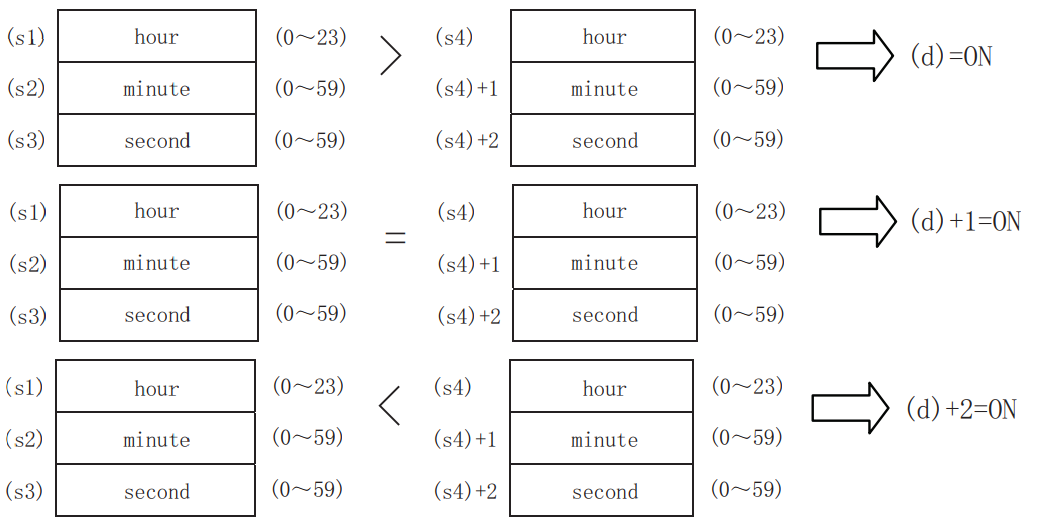
Compare the comparison time specified in (s1), (s2), (s3) with the time data specified in (s4), and turn the bit device specified in (d) ON/OFF according to their size match.
-[TCMP (s1) (s2) (s3) (s4) (d)]
Content, range and data type
| Parameter | Content | Range | Data type | Data type (label) |
| (s1) | Specify the "hour" of the comparison base time. | 0 to 23 | Signed BIN 16 bit | ANY16 |
| (s2) | Specify the "minute" of the comparison base time. | 0 to 59 | Signed BIN 16 bit | ANY16 |
| (s3) | Specify the "second" of the comparison base time. | 0 to 59 | Signed BIN 16 bit | ANY16 |
| (s4) | Specify the "hour" of the time data (hour, minute, second). | - | Signed BIN 16 bit | ANY16_ARRAY |
| (d) | The bit device is turned ON/OFF according to the comparison result. | - | Bit | ANYBIT_ARRAY |
Device used
| Instruction | Parameter | Devices | Offset modification | Pulse extension | |||||||||||||||||||||||
| X | Y | M | S | SM | T(bit) | C(bit) | LC(bit) | HSC(bit) | D.b | KnX | KnY | KnM | KnS | T | C | D | R | SD | LC | HSC | K | H | E | [D] | XXP | ||
| TCMP | Parameter 1 | ● | ● | ● | ● | ● | ● | ● | ● | ● | ● | ● | ● | ● | |||||||||||||
| Parameter 2 | ● | ● | ● | ● | ● | ● | ● | ● | ● | ● | ● | ● | ● | ||||||||||||||
| Parameter 3 | ● | ● | ● | ● | ● | ● | ● | ● | ● | ● | ● | ● | ● | ||||||||||||||
| Parameter 4 | ● | ● | ● | ● | ● | ● | ● | ||||||||||||||||||||
| Parameter 5 | ● | ● | ● | ● | ● | ● | ● | ||||||||||||||||||||
Features
Compare the time of the reference time (hour, minute, second) [(s1), (s2), (s3)] with the time data (hour, minute, second) [(s4), (s4)+1, (s4) +2] Compare the size and turn on/off the 3 points from (d) according to the result of the same size.
✎Note
The device specified in (s4) and (d) occupies 3 points. Be careful not to overlap with the device used for machine control.
When using the clock data time (hour, minute, second) of the built-in real-time clock of the CPU module, use the TRD(P) instruction to read the value of the special register and assign the word device to each operand.
Error code
| Error code | Content |
| 4085H | When reading the specified device range exceeds the corresponding device range |
| 4086H | When writing the specified device range exceeds the corresponding device range |
| 4084H | When the value specified in (s) and (s4) is not in the range of 0 to 23 When the value specified in (s2),(s3) (s4)+1 and (s4)+2 is not in the range of 0 to 59 |
Example

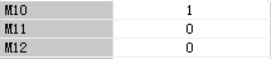
Set D10 to 1, D11 to 30, D12 to 0
When M0 is turned on, the time that D23 will come is 0:31:27

M10 is turned ON
TZCP/Clock data bandwidth comparison
TZCP(P)
Compare the comparison time of the high and low points specified in (s1) and (s2) with the time data specified in (s3), and turn the bit device specified in (d) ON/OFF according to its size and bandwidth.
-[TZCP (s1) (s2) (s3) (d)]
Content, range and data type
| Parameter | Content | Range | Data type | Data type (label) |
| (s1) | Specify the "hour" of the lower limit time (hour, minute, second) | - | Signed BIN 16 bit | ANY16_ARRAY (number of elements: 3) |
| (s2) | Specify the "hour" of the lower limit time (hour, minute, second) | - | Signed BIN 16 bit | ANY16_ARRAY (number of elements: 3) |
| (s3) | Specify "hour" of time data (hour, minute, second) | - | Signed BIN 16 bit | ANY16_ARRAY (number of elements: 3) |
| (d) | The bit device is turned ON/OFF according to the comparison result. | - | Bit | ANY16_ARRAY (number of elements: 3) |
Device used
| Instruction | Parameter | Devices | Offset modification | Pulse extension | |||||||||||||||||||||||
| X | Y | M | S | SM | T(bit) | C(bit) | LC(bit) | HSC(bit) | D.b | KnX | KnY | KnM | KnS | T | C | D | R | SD | LC | HSC | K | H | E | [D] | XXP | ||
| TZCP | Parameter 1 | ● | ● | ● | ● | ● | ● | ● | |||||||||||||||||||
| Parameter 2 | ● | ● | ● | ● | ● | ● | ● | ||||||||||||||||||||
| Parameter 3 | ● | ● | ● | ● | ● | ● | ● | ||||||||||||||||||||
| Parameter 4 | ● | ● | ● | ● | ● | ● | ● | ||||||||||||||||||||
Features
Compare the comparison time of the high and low points specified in (s1) and (s2) with the time data specified in (s3), and turn the bit device specified in (d) ON/OFF according to its size and bandwidth.

✎Note
• The devices specified in (s1), (s2), (s3), (d) occupy 3 points. Be careful not to overlap with the device used for machine control.
• When using the clock data time (hour, minute, second) of the built-in real-time clock of the CPU module, use the TRD(P) instruction to read the value of the special register and assign the word device to each operand.
• When (s1)> (s2), two of (d), (d)+1, (d)+2 are ON/OFF.
Error code
| Error code | Content |
| 4085H | When reading the specified device range exceeds the corresponding device range |
| 4086H | When writing the specified device range exceeds the corresponding device range |
| 4084H | When the value specified in (s1), (s2) and (s3) is not in the range of 0 to 23 When the value specified in (s1)+1, (s2)+1, (s3)+1, (s1)+2, (s2)+2 and (s3)+2 is not in the range of 0 to 59 |
Example

Set D0 time to 16:30:00 and D10 time to 4:30:0
After the coil is turned on, the reading time to D20 time is 8:30:00

M0/M12 is ON

 7.13 Data control instructions
BAND/BIN 16-bit data dead zone control
BAND(P)
The input value (BIN 16-bit value) specified in (s3) controls the output value stored in the device specified in (d) according to the upper and lower limits of the dead zone specified in (s1) and (s2).
-[BAND (s1) (s2) (S3) (d)]
Content, range and data type
| Parameter | Content | Range | Data type | Data type (label) |
| (s1) | Lower limit of dead zone (no output zone) | -32,768 to +32,767 | Signed BIN 16 bit | ANY16_S |
| (s2) | Upper limit of dead zone (no output zone) | -32,768 to +32,767 | Signed BIN 16 bit | ANY16_S |
| (S3) | Input value controlled by dead zone control | -32768 to +32,767 | Signed BIN 16 bit | ANY16_S |
| (D) | The start number of the device that stores the output value controlled by the dead zone control | - | Signed BIN 16 bit | ANY16_S |
Device used
| Instruction | Parameter | Devices | Offset modification | Pulse extension | |||||||||||||||||||||||
| X | Y | M | S | SM | T(bit) | C(bit) | LC(bit) | HSC(bit) | D.b | KnX | KnY | KnM | KnS | T | C | D | R | SD | LC | HSC | K | H | E | [D] | XXP | ||
| BAND | Parameter 1 | ● | ● | ● | ● | ● | ● | ● | ● | ● | ● | ● | ● | ● | |||||||||||||
| Parameter 2 | ● | ● | ● | ● | ● | ● | ● | ● | ● | ● | ● | ● | ● | ||||||||||||||
| Parameter 3 | ● | ● | ● | ● | ● | ● | ● | ● | ● | ● | ● | ||||||||||||||||
| Parameter 4 | ● | ● | ● | ● | ● | ● | ● | ● | ● | ● | |||||||||||||||||
Features
The input value (BIN 16-bit value) specified in (s3) controls the output value stored in the device specified in (d) according to the upper and lower limits of the dead zone specified in (s1) and (s2). The output value is controlled as follows.
| Condition | The value stored in the output value |
| When dead zone low limit (s1)> input value (s3) | Input value (s3)-Dead zone low limit (s1) |
| When dead zone high limit (s1) <input value (s3) | Input value (s3)- Dead zone high limit (s2) |
| When dead zone low limit (s1) ≤ input value (s3) ≤ dead zone low limit (s2) | 0 |
•When the output value stored in (d) is a signed BIN 16-bit value, and the operation result exceeds the range of -32768 to 32767, the situation is shown in the following example.
For example, when (s1) is 10 and (s3) is -32768,
the output value = -32768-10=8000H-000AH=7FFFH=32758.

Error code
| Error code | Content |
| 4085H | When the specified device range for reading exceeds the range of the corresponding device. |
| 4086H | When the specified device range for writing exceeds the range of the corresponding device. |
| 4084H | When the low limit specified in (s1) is greater than the high limit specified in (s2). |
Example

When X000 is ON, when D0<(-1,000), the value of ( D0)-(-1,000) is stored in (D1).
• When -1,000≦ D0≦1,000, 0 is stored in D1.
• When D0<1,000, the value of (D0)-1,000 is stored in D1.
DBAND/BIN 32-bit data dead zone control
DBAND(P)
The input value (BIN 32-bit value) specified in (s3) controls the output value stored in the device specified in (d) according to the upper and lower limits of the dead zone specified in (s1) and (s2).
-[DBAND (s1) (s2) (S3) (d)]
Content, range and data type
| Parameter | Content | Range | Data type | Data type (label) |
| (s1) | Dead zone low limit (no output zone) | -2,147,483,648 to +2,147,483,647 | Signed BIN 32 bit | ANY32_S |
| (s2) | Dead zone high limit (no output zone) | -2,147,483,648 to +2,147,483,647 | Signed BIN 32 bit | ANY32_S |
| (S3) | Input value controlled by dead zone control | -2,147,483,648 to +2,147,483,647 | Signed BIN 32 bit | ANY32_S |
| (d) | The start number of the device that stores the output value controlled by the dead zone control | - | Signed BIN 32 bit | ANY32_S |
Device used
| Instruction | Parameter | Devices | Offset modification | Pulse extension | |||||||||||||||||||||||
| X | Y | M | S | SM | T(bit) | C(bit) | LC(bit) | HSC(bit) | D.b | KnX | KnY | KnM | KnS | T | C | D | R | SD | LC | HSC | K | H | E | [D] | XXP | ||
| DBAND | Parameter 1 | ● | ● | ● | ● | ● | ● | ● | ● | ● | ● | ● | ● | ● | ● | ● | |||||||||||
| Parameter 2 | ● | ● | ● | ● | ● | ● | ● | ● | ● | ● | ● | ● | ● | ● | ● | ||||||||||||
| Parameter 3 | ● | ● | ● | ● | ● | ● | ● | ● | ● | ● | ● | ● | ● | ||||||||||||||
| Parameter 4 | ● | ● | ● | ● | ● | ● | ● | ● | ● | ● | ● | ● | |||||||||||||||
Features
The input value (BIN 32-bit value) specified in (s3) controls the output value stored in the device specified in (d) according to the upper and lower limits of the dead zone specified in (s1) and (s2). The output value is controlled as follows.
| Condition | The value stored in the output value |
| When dead zone low limit ((s1), (s1)+1)> input value ((s3), (s3)+1) | Input value ((s3), (s3)+1)-dead zone low limit ((s1), (s1)+1) |
| When dead zone high limit ((s1), (s1)+1) <input value ((s3), (s3)+1) | Input value ((s3), (s3)+1)-dead zone high limit ((s2), (s2)+1) |
| When dead zone low limit ((s1), (s1)+1) ≤ input value ((s3), (s3)+1) ≤ dead zone high limit ((s2), (s2)+1) | 0 |
• When the output value stored in (d) is a signed BIN 32-bit value, and the operation result exceeds the range of -2,147,483,648 to 2,147,483,647, the situation is as the following example. For example, When (s1) and (s1)+1 are 1000, (s3) and (s3)+1 are -2,147,483,648, then the output value=
-2,147,483,648-1000=80000000H-000003E8H=7FFFFC18H=2,147,482,648.

Error code
| Error code | Content |
| 4085H | When the specified device range for reading exceeds the range of the corresponding device. |
| 4086H | When the specified device range for writing exceeds the range of the corresponding device. |
| 4084H | When the low limit specified in (s1) is greater than the high limit specified in (s2). |
Example

• When (D1, D0)<(-10,000), the value of (D1, D0)-(-10,000) is stored in (D11, D10).
• When -10,000≦(D1, D0)≦10,000, 0 is stored in (D11, D10).
• When 10,000< (D1, D0), the value of (D1, D0)-10,000 is stored in D1.
BINDA/BIN 16-bit data → Decimal ASCII conversion
BINDA(P)
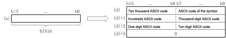
Convert the BIN 16-bit data specified in (s) and the value of each digit in decimal numbers into ASCII codes and store them after the device number specified in (d).
-[BINDA(s)(d)]
Content, range and data type
| Parameter | Content | Range | Data type | Data type (label) |
| (s) | BIN data for ASCII conversion | -32768 to +32767 | Signed BIN 16 bit | ANY16_S |
| (d) | The start number of the device storing the conversion result | - | String | ANYSTRING_SINGLE |
Device used
| Instruction | Parameter | Devices | Offset modification | Pulse extension | |||||||||||||||||||||||
| X | Y | M | S | SM | T(bit) | C(bit) | LC(bit) | HSC(bit) | D.b | KnX | KnY | KnM | KnS | T | C | D | R | SD | LC | HSC | K | H | E | [D] | XXP | ||
| BINDA | Parameter 1 | ● | ● | ● | ● | ● | ● | ● | ● | ● | ● | ● | ● | ● | |||||||||||||
| Parameter 2 | ● | ● | ● | ● | ● | ||||||||||||||||||||||
Features
Convert the BIN 16-bit data specified in (s) and the value of each digit in decimal numbers into ASCII codes and store them after the device number specified in (d).
←Only store 0 when SM191 is OFF
For example, when -12,345 is specified in (s) (in the case of specifying signed)

The calculation result stored in (d) will be as below.
• In "Sign", 20H is stored when the BIN data is positive, and 2DH is stored when it is negative.
• In the 0 to the left of the effective digit, 20H is stored. (Suppress 0.) For example, in the case of "00325", "00" becomes 20H, and "325" becomes the effective digit.
• When storing data to the device specified in (d)+3, when SM191 (output character number switching signal) is OFF, 0 is stored, and it does not change when it is ON.
✎Note: The number of occupied points of (d) is 3 when SM191 is ON, and it is 4 when SM191 is OFF.
Error code
| Error code | Content |
| 4085H | The read address of (s) exceeds the device range. |
| 4086H | The write address of (d) exceeds the device range. |
Example
When X000 is ON, convert the value of 16-bit data (BIN) D1000 into decimal ASCII code, and then use PR instruction to output the
converted ASCII code character by character to the program of Y040 to Y057.

DBINDA/BIN 32-bit data → Decimal ASCII conversion
DBINDA(P)
Convert the BIN 32-bit data specified in (s) and the value of each bit in decimal numbers into ASCII codes and store them after the device number specified in (d).
-[DBINDA(s)(d)]
Content, range and data type
| Parameter | Content | Range | Data type | Data type (label) |
| (s) | BIN data for ASCII conversion | -2,147483648 to 2147483647 | Signed BIN 32 bit | ANY32_S |
| (d) | The start number of the device storing the conversion result | - | String | ANYSTRING_SINGLE |
Device used
| Instruction | Parameter | Devices | Offset modification | Pulse extension | |||||||||||||||||||||||
| X | Y | M | S | SM | T(bit) | C(bit) | LC(bit) | HSC(bit) | D.b | KnX | KnY | KnM | KnS | T | C | D | R | SD | LC | HSC | K | H | E | [D] | XXP | ||
| DBINDA | Parameter 1 | ● | ● | ● | ● | ● | ● | ● | ● | ● | ● | ● | ● | ● | ● | ● | |||||||||||
| Parameter 2 | ● | ● | ● | ● | ● | ||||||||||||||||||||||
Features
Convert the BIN 32-bit data specified in (s) and the value of each bit when expressed in decimal numbers into ASCII codes, and store them after the device number specified in (d).
For example, when -12345678 is specified in (s). (in the case of specifying signed)
 The calculation result stored in (d) will be as below.
• In "Sign", 20H is stored when the BIN data is positive, and 2DH is stored when it is negative.
• 20H is stored at 0 to the left of the effective number of digits. (Suppress 0.) For example, in the case of "0012034560", "00" becomes 20H, and "12034560" becomes effective digits.
• For the data stored in the upper 8 bits of the device specified in (d)+5, 0 will be stored when SM191 (output character switching signal) is OFF, and 20H will be stored when it is ON.
✎Note: (d) Occupies 6 points.
Error code
| Error code | Content |
| 4085H | (s) read address exceeds the device range |
| 4086H | (d) write address exceeds the device range |
Example

When X000 is ON, convert the value of 32-bit data (BIN) D1000 into decimal ASCII code, and then use PR (FNC 77) instruction to output the converted ASCII code character by character to the program in Y040 to Y051 in time and time division.
DABIN/Decimal ASCII → BIN conversion
DABIN(P)
Digital ASCII code (30H to 39H) is a instruction to convert real data into BIN data.
-[DABIN (s) (d)]
Content, range and data type
| Parameter | Content | Range | Data type | Data type (label) |
| (s) | The start number of the device that stores the data (ASCII code) to be converted into a BIN value | - | String | ANYSTRING_SINGLE |
| (d) | The device number for storing conversion result | - | BIN16 bit | ANY16_S |
Device used
| Instruction | Parameter | Devices | Offset modification | Pulse extension | |||||||||||||||||||||||
| X | Y | M | S | SM | T(bit) | C(bit) | LC(bit) | HSC(bit) | D.b | KnX | KnY | KnM | KnS | T | C | D | R | SD | LC | HSC | K | H | E | [D] | XXP | ||
| DABIN | Parameter 1 | ● | ● | ● | ● | ● | |||||||||||||||||||||
| Parameter 2 | ● | ● | ● | ● | ● | ● | ● | ● | ● | ● | |||||||||||||||||
Features
The decimal ASCII data stored after the device number specified in (s) is converted into BIN 16-bit data and stored in the device specified in (d).
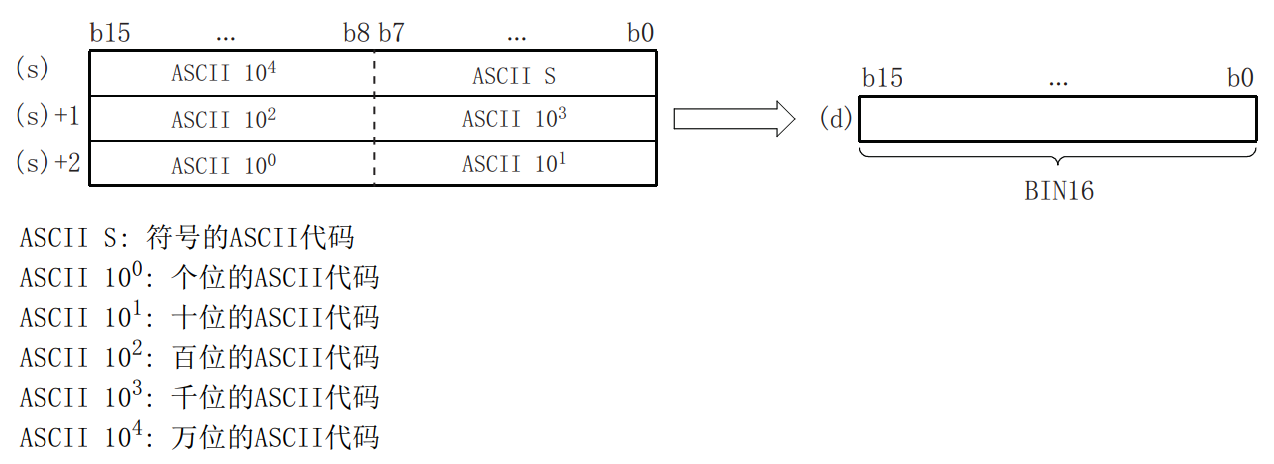
| ASCII S | ASCII 100 | ASCII 101 | ASCII 102 | ASCII 103 | ASCII 104 |
| ASCII code | Units of ASCII code | Tens of ASCII code | Hundreds of ASCII code | Thousands of ASCII code | Ten thousands of ASCII code |
For example, When -25,108 is specified in (s)

• The ASCII data specified in (s) to (s)+2 is within the range of -32,768 to +32,767.
• In “Sign”, set 20H when the converted data is positive, and set 2DH when it is negative. (When other than 20H or 2DH is set, it will be treated as positive data. (DABIN(P))
• The range of the ASCII code set in each digit is 30H to 39H.
• When the ASCII code set in each bit is 20H or 00H, it will be treated as 30H.
Error code
| Error code | Content |
| 4084H | When the Sign data exceeds the range of 30H to 39H, 20H, 00H, 2DH; When the ASCII code of each bit specified in (s) to (s)+2 exceeds the range of 30H to 39H, 20H, 00H; When the ASCII data specified in (s) to (s)+2 is other than -32,768 to +32,767. |
| 4085H | The read address of (s) exceeds the device range. |
| 4086H | The write address of (d) exceeds the device range. |
When X000 is ON, the Signs set in D20 to D22 and the ASCII code data of 5-digit decimal numbers are converted into BIN values, and then stored in the program of D0.
Example

DDABIN/Decimal ASCII → BIN32-bit data conversion
DDABIN(P)
The decimal ASCII data stored after the device number specified in (s) is converted into BIN 32-bit data and stored in the device number specified in (d).
-[DDABIN (s) (d) ]
Content, range and data type
| Parameter | Content | Range | Data type | Data type (label) |
| (s) | The start number of the device that stores data (ASCII code) to be converted into a BIN value | - | String | ANYSTRING_SINGLE |
| (d) | The device number for storing conversion result | - | Signed BIN 32 bit | ANY32_S |
Device used
| Instruction | Parameter | Devices | Offset modification | Pulse extension | |||||||||||||||||||||||
| X | Y | M | S | SM | T(bit) | C(bit) | LC(bit) | HSC(bit) | D.b | KnX | KnY | KnM | KnS | T | C | D | R | SD | LC | HSC | K | H | E | [D] | XXP | ||
| DDABIN | Parameter 1 | ● | ● | ● | ● | ● | |||||||||||||||||||||
| Parameter 2 | ● | ● | ● | ● | ● | ● | ● | ● | ● | ● | ● | ● | |||||||||||||||
Features
The decimal ASCII data stored after the device number specified in (s) is converted into BIN 32-bit data and stored in the device specified in (d).

| ASCII S | ASCII code | ASCII S | ASCII code |
| ASCII 100 | Units of ASCII code | ASCII 105 | Hundred thousands of ASCII code |
| ASCII 101 | Tens of ASCII code | ASCII 106 | Millions of ASCII code |
| ASCII 102 | Hundreds of ASCII code | ASCII 107 | Ten millions of ASCII code |
| ASCII 103 | Thousands of ASCII code | ASCII 108 | Hundred millions of ASCII code |
| ASCII 104 | Tens thousands of ASCII code | ASCII 109 | billions of ASCII code |
When -1234543210 is specified in (s) (When signed is specified)

• The ASCII data specified in (s) to (s)+5 is within the range of -2,147,483,648 to +2,147,483,647. In addition, the data stored in the high byte of (s)+5 will be ignored.
• In the Sign data, set 20H when the converted data is positive, and set 2DH when it is negative. (When other than 20H or 2DH is set, it will be treated as positive data. (DABIN(P))
• The range of ASCII code set in each digit is 30H to 39H.
• When the ASCII code set in each bit is 20H or 00H, it will be treated as 30H.
Error code
| Error code | Content |
| 4084H | When the Sign data exceeds the range of 30H to 39H, 20H, 00H and 2DH; When the ASCII code of each bit specified in (s) to (s)+5 exceeds the range of 30H to 39H, 20H and 00H; When the ASCII data specified in (s) to (s)+5 exceeds the range of -2,147,483,648 to +2,147,483,647 |
| 4085H | The read address of (s) exceeds the device range. |
| 4086H | The write address of (d) exceeds the device range. |
Example

When X000 is ON, the Signs set in to D20 to D25 and the ASCII code data of 10-digit decimal numbers are converted into BIN values and then saved to the program in D0 to D1.
LIMIT/ BIN 16-bit data high and low limit control
LIMIT(P)
The input value (BIN 16-bit value) specified in (s3) controls the output value stored in the device specified in (d) according to the upper and lower limit value ranges specified in (s1) and (s2).
-[LIMIT (s1) (s2) (s3) (d)]
Content, range and data type
| Parameter | Content | Range | Data type | Data type (label) |
| s1 | Low limit value (minimum output limit value) | -32,768 to 32,767 | BIN16 bit | ANY16_S |
| s2 | High limit value (maximum output limit value) | -32,768 to 32,767 | BIN16 bit | ANY16_S |
| s3 | Input value controlled by high and low limit control | -32,768 to 32,767 | BIN16 bit | ANY16_S |
| d | The start number of device that stores the output value controlled by high and low limit control | - | BIN16 bit | ANY16_S |
Device used
| Instruction | Parameter | Devices | Offset modification | Pulse extension | |||||||||||||||||||||||
| X | Y | M | S | SM | T(bit) | C(bit) | LC(bit) | HSC(bit) | D.b | KnX | KnY | KnM | KnS | T | C | D | R | SD | LC | HSC | K | H | E | [D] | XXP | ||
| LIMIT | Parameter 1 | ● | ● | ● | ● | ● | ● | ● | ● | ● | ● | ● | ● | ● | |||||||||||||
| Parameter 2 | ● | ● | ● | ● | ● | ● | ● | ● | ● | ● | ● | ● | ● | ||||||||||||||
| Parameter 3 | ● | ● | ● | ● | ● | ● | ● | ● | ● | ● | ● | ||||||||||||||||
| Parameter 4 | ● | ● | ● | ● | ● | ● | ● | ● | ● | ● | |||||||||||||||||
Features
The input value (BIN 16-bit value) specified in (s3) controls the output value stored in the device specified in (d) according to the high and low limit value ranges specified in (s1) and (s2). The output value is controlled as follows.
| Condition | The value stored in the output value |
| Low limit value (s1)>input value (s3) | Low limit value (s1) |
| High limit value (s1) <input value (s3) | High limit value (s2) |
| Low limit value (s1) ≤ input value (s3) ≤ high limit value (s2) | Input value (s3) |
•Only in the case of controlling high limit value, set the minimum value of data range in the low limit value specified in (s1).
• Only in the case of controlling low limit value, set the maximum value of data range in the high limit value specified in (s2).

Error code
| Error code | Content |
| 4085H | The read address exceeds the device range |
| 4086H | The write address exceeds the device range |
| 4084H | High limit <low limit |
Example

When X000 is ON
• When D0 <500, D1 is 500.
• When 500 ≤ D0 ≤ 5,000, D1 is the value of D0.
• When 5,000 <D0, D1 is 5,000.
DLIMIT/BIN 32-bit data high and low limit control
DLIMIT(P)
The input value (BIN 32-bit value) specified in (s3) controls the output value stored in the device specified in (d) according to the range of high and low limit values specified in (s1) and (s2).
-[DLIMIT (s1) (s2) (s3) (d)]
Content, range and data type
| Parameter | Content | Range | Data type | Data type (label) |
| s1 | Low limit value (minimum output limit value) | -2,147,483,648 to 2,147,483,647 | BIN32 bit | ANY32_S |
| s2 | High limit value (maximum output limit value) | -2,147,483,648 to 2,147,483,647 | BIN32 bit | ANY32_S |
| s3 | Input value controlled by high and low limit control | -2,147,483,648 to 2,147,483,647 | BIN32 bit | ANY32_S |
| d | The start number of the device that stores the output value controlled by high and low limit control | - | BIN32 bit | ANY32_S |
Device used
| Instruction | Parameter | Devices | Offset modification | Pulse extension | |||||||||||||||||||||||
| X | Y | M | S | SM | T(bit) | C(bit) | LC(bit) | HSC(bit) | D.b | KnX | KnY | KnM | KnS | T | C | D | R | SD | LC | HSC | K | H | E | [D] | XXP | ||
| DLIMIT | Parameter 1 | ● | ● | ● | ● | ● | ● | ● | ● | ● | ● | ● | ● | ● | ● | ● | |||||||||||
| Parameter 2 | ● | ● | ● | ● | ● | ● | ● | ● | ● | ● | ● | ● | ● | ● | ● | ||||||||||||
| Parameter 3 | ● | ● | ● | ● | ● | ● | ● | ● | ● | ● | ● | ● | ● | ||||||||||||||
| Parameter 4 | ● | ● | ● | ● | ● | ● | ● | ● | ● | ● | ● | ● | |||||||||||||||
Features
The input value (BIN 32-bit value) specified in (s3) controls the output value stored in the device specified in (d) according to the range of high and low limit values specified in (s1) and (s2). The output value is controlled as follows.
| Condition | The value stored in the output value |
| Low limit value ((s1), (s1)+1)> input value ((s3), (s3)+1) | Low limit value ((s1), (s1)+1) |
| High limit value ((s2), (s2)+1) <input value ((s3), (s3)+1) | High limit value ((s2), (s2)+1) |
| Low limit value ((s1), (s1)+1) ≤ input value ((s3), (s3)+1) ≤ high limit value ((s2), (s2)+1) | Input value ((s3), (s3)+1) |
•Only in the case of controlling high limit value, set the minimum value of data range in the low limit value specified in (s1).
• Only in the case of controlling low limit value, set the maximum value of data range in the high limit value specified in (s2).
Error code
| Error code | Content |
| 4085H | The read address exceeds the device range |
| 4086H | The write address exceeds the device range |
| 4084H | High limit <low limit |
Example

Operation:
• When (D1, D0) <10,000, (D11, D10) is 10,000.
• When 10,000 ≤ (D1, D0) ≤ 1,000,000, (D11, D10) is the value of (D1, D0).
• When 1,000,000 <(D1, D0), (D11, D10) is 1,000,000.
SCL/BIN 16-bit unit scale (coordinate data of each point)
SCL(P)
The scaling conversion data (16-bit data unit) specified in (s2) is scaled from the input value specified in (s1), and the calculation result is stored in the device specified in (d).
-[SCL (s1) (s2) (d)]
Content, range and data type
| Parameter | Content | Range | Data type | Data type (label) |
| (s1) | The input value for scaling or the start number of device storing the input value | -32,768 to 32,767 | Signed BIN 16 bit | ANY16_S |
| (s2) | The start number of the device storing conversion data for scaling | - | Signed BIN 16 bit | ANY16_S |
| (d) | The start number of the device that stores the output value controlled by scaling | - | Signed BIN 16 bit | ANY16_S |
Device used
| Instruction | Parameter | Devices | Offset modification | Pulse extension | |||||||||||||||||||||||
| X | Y | M | S | SM | T(bit) | C(bit) | LC(bit) | HSC(bit) | D.b | KnX | KnY | KnM | KnS | T | C | D | R | SD | LC | HSC | K | H | E | [D] | XXP | ||
| SCL | Parameter 1 | ● | ● | ● | ● | ● | ● | ● | ● | ● | ● | ● | ● | ● | |||||||||||||
| Parameter 2 | ● | ● | ● | ● | ● | ||||||||||||||||||||||
| Parameter 3 | ● | ● | ● | ● | ● | ● | ● | ● | ● | ● | |||||||||||||||||
Features
For the scale conversion data (16-bit data unit) specified in (s2), scale by the input value specified in (s1), and store the operation result in the device specified in (d). Scale conversion is performed based on the scale conversion data stored after the device specified in (s2).
| Setting items (n represents the number of coordinate points specified in (s2)) | Device allocation | |
| Coordinate points | (s2) | |
| Point 1 | X coordinate | (s2)+1 |
| Y coordinate | (s2)+2 | |
| Point 2 | X coordinate | (s2)+3 |
| Y coordinate | (s2)+4 | |
| ........ | ||
| Point n | X coordinate | (s2)+2n-1 |
| Y coordinate | (s2)+2n | |
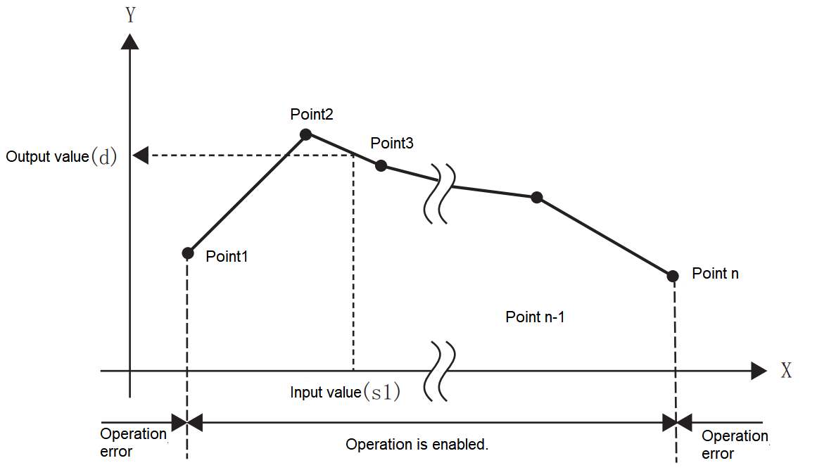
• If the operation result is not an integer value, round the first digit below the decimal point.
• The X coordinate data of the conversion data for scaling should be set in ascending order.
• (s1) should be set within the range of conversion data for scaling (device value of (s2)).
• If the same X coordinate is specified for multiple points, the Y coordinate value of the second point will be output.
• Set the number of coordinate points of the conversion data for scaling within the range of 1 to 32,767.
• Setting example of conversion table for scaling.
In the case of scaling conversion characteristics as shown in the figure below, set it as the following data sheet.

| Set items | Sett device and content | Remarks | |||
| When R0 is specified in (s2) | Set content | ||||
| Coordinate points | (s2) | R0 | K10 | ||
| Point 1 | X coordinate | (s2)+1 | R1 | K5 | |
| Y coordinate | (s2)+2 | R2 | K20 | ||
| Point 2 | X coordinate | (s2)+3 | R3 | K30 | |
| Y coordinate | (s2)+4 | R4 | K50 | ||
| Point 3 | X coordinate | (s2)+5 | R5 | K100 | |
| Y coordinate | (s2)+6 | R6 | K200 | ||
| Point 4 | X coordinate | (s2)+7 | R7 | K25 | If the coordinates are specified by 3 points, the intermediate value could be the output value. In this example, the output value (median value) is specified by the Y coordinate of point 5. When the X coordinate is the same at 3 points or more, the value of the 2nd point is also output. |
| Y coordinate | (s2)+8 | R8 | K200 | ||
| Point 5 | X coordinate | (s2)+9 | R9 | K70 | |
| Y coordinate | (s2)+10 | R10 | K200 | ||
| Point 6 | X coordinate | (s2)+11 | R11 | K250 | |
| Y coordinate | (s2)+12 | R12 | K250 | ||
| Point 7 | X coordinate | (s2)+13 | R13 | K250 | |
| Y coordinate | (s2)+14 | R14 | K90 | ||
| Point 8 | X coordinate | (s2)+15 | R15 | K350 | If the coordinates are specified by two points, the output value is the value of the Y coordinate of the next point. In this example, the output value is specified by the Y coordinate of point 9. |
| Y coordinate | (s2)+16 | R16 | K90 | ||
| Point 9 | X coordinate | (s2)+17 | R17 | K350 | |
| Y coordinate | (s2)+18 | R18 | K30 | ||
| Point 10 | X coordinate | (s2)+19 | R19 | K400 | |
| Y coordinate | (s2)+20 | R20 | K7 | ||
Error code
| Error code | Content |
| 4085H | When the specified device range for reading exceeds the range of the corresponding device. |
| 4086H | When the specified device range for writing exceeds the range of the corresponding device. |
| 4084H | When the Xn data of data table is not sorted in ascending order. However, the instruction will be executed until the position where the error occurs; When the input value specified in (s1) exceeds the range of the set scale conversion data; When the number of start coordinate points of device (s2) is less than 0. |
Example

 When -100 ≤ D0(X) < 0, D100(Y)=
 when D0(X)=0, D100(Y)=0;
when 0< D0(X) ≤ 100, D100(Y)=

DSCL/32-bit unit scale (coordinate data of each point)
DSCL(P)
The conversion data (32-bit data unit) for scaling specified in (s2) is scaled by the input value specified in (s1), and the operation result is stored in the device specified in (d).
-[DSCL (s1) (s2) (d)]
Content, range and data type
| Parameter | Content | Range | Data type | Data type (label) |
| (s1) | The input value for scaling or the start number of the device storing the input value | -2,147,483,648 to 2,147,483,647 | Signed BIN 32 bit | ANY32_S |
| (s2) | The start number of the device storing conversion data for scaling | - | Signed BIN 32 bit | ANY32_S |
| (d) | The start number of the device that stores the output value controlled by scaling | - | Signed BIN 32 bit | ANY32_S |
Device used
| Instruction | Parameter | Device | Offset modification | Pulse extension | |||||||||||||||||||||||
| X | Y | M | S | SM | T(bit) | C(bit) | LC(bit) | HSC(bit) | D.b | KnX | KnY | KnM | KnS | T | C | D | R | SD | LC | HSC | K | H | E | [D] | XXP | ||
| DSCL | Parameter 1 | ● | ● | ● | ● | ● | ● | ● | ● | ● | ● | ● | ● | ● | ● | ● | |||||||||||
| Parameter 2 | ● | ● | ● | ● | ● | ||||||||||||||||||||||
| Parameter 3 | ● | ● | ● | ● | ● | ● | ● | ● | ● | ● | ● | ● | |||||||||||||||
Features
The conversion data (32-bit data unit) for scaling specified in (s2) is scaled by the input value specified in (s1), and the operation result is stored in the device number specified in (d). The scale conversion is performed based on the scale conversion data stored after the device specified in (s2).
| Set items (n represents the number of coordinate points specified in (s2)) | Device allocation | |
| Coordinate points | (s2)+1, (s2) | |
| Point 1 | X coordinate | (s2)+3, (s2)+2 |
| Y coordinate | (s2)+5, (s2)+4 | |
| Point 2 | X coordinate | (s2)+7, (s2)+6 |
| Y coordinate | (s2)+9, (s2)+8 | |
| ........ | ||
| Point n | X coordinate | (s2)+4n-1, (s2)+4n-2 |
| Y coordinate | (s2)+4n+1, (s2)+4n | |

• If the calculation result is not an integer value, round the first digit below the decimal point.
• The X coordinate data of the conversion data for scaling should be set in ascending order.
• For (s1), set within the range of the conversion data for scaling ((s2), (s2) + 1 device value).
• If the same X coordinate is specified for multiple points, the Y coordinate value of the second point will be output.
• Set the number of coordinate points of conversion data for scaling within the range of 1 to 2,147,483,647.
• Setting example of conversion table for scaling.
In the case of scaling conversion characteristics as shown in the figure below, set it as the following data sheet.
| Set items | Set device and content | Remarks | |||
| When R0 is specified in (s2) | Set content | ||||
| Coordinate points | (s2)+1, (s2) | R1, R0 | K10 | ||
| Point 1 | X coordinate | (s2)+3, (s2)+2 | R3, R2 | K5 | |
| Y coordinate | (s2)+5, (s2)+4 | R5, R4 | K7 | ||
| Point 2 | X coordinate | (s2)+7, (s2)+6 | R7, R6 | K20 | |
| Y coordinate | (s2)+9, (s2)+8 | R9, R8 | K30 | ||
| Point 3 | X coordinate | (s2)+11, (s2)+10 | R10, R11 | K50 | |
| Y coordinate | (s2)+13, (s2)+12 | R13, R12 | K100 | ||
| Point 4 | X coordinate | (s2)+15, (s2)+14 | R15, R14 | K200 | if the coordinates are specified by 3 points, the intermediate value could be the output value. In this example, the output value (median value) is specified by the Y coordinate of point 5. When the X coordinate is the same at 3 points or more, the value of the 2nd point is also output. |
| Y coordinate | (s2)+17, (s2)+16 | R17, R16 | K25 | ||
| Point 5 | X coordinate | (s2)+19, (s2)+18 | R19, R18 | K200 | |
| Y coordinate | (s2)+21, (s2)+20 | R21, R20 | K70 | ||
| Point 6 | X coordinate | (s2)+23, (s2)+22 | R23, R22 | K200 | |
| Y coordinate | (s2)+25, (s2)+24 | R25, R24 | K250 | ||
| Point 7 | X coordinate | (s2)+27, (s2)+26 | R27, R26 | K250 | |
| Y coordinate | (s2)+29, (s2)+28 | R29, R28 | K90 | ||
| Point 8 | X coordinate | (s2)+31, (s2)+30 | R31, R30 | K350 | If the coordinates are specified by two points, the output value is the value of the Y coordinate of the next point. In this example, the output value is specified by the Y coordinate of point 9. |
| Y coordinate | (s2)+33, (s2)+32 | R33, R32 | K90 | ||
| Point 9 | X coordinate | (s2)+35, (s2)+34 | R35, R34 | K350 | |
| Y coordinate | (s2)+37, (s2)+36 | R37, R36 | K30 | ||
| Point 10 | X coordinate | (s2)+39, (s2)+38 | R39, R38 | K400 | |
| Y coordinate | (s2)+41, (s2)+40 | R41, R40 | K7 | ||
Error code
| Error code | Content |
| 4085H | When the specified device range for reading exceeds the range of the corresponding device. |
| 4086H | When the specified device range for writing exceeds the range of the corresponding device. |
| 4084H | When the Xn data of data table is not sorted in ascending order. However, the instruction will be executed until the position where the error occurs; When the input value specified in (s1) exceeds the range of the set scale conversion data; When the number of start coordinate points of device (s2) is less than 0. |
Example

 When -100 ≤ D0(X) < 0, D100(Y)=
When D0(X)=0, D100(Y)=0;
When 0 < D0(X) ≤ 100, D100(Y)=

SCL2/BIN 16-bit unit scale (X/Y coordinate data)
SCL2(P)
The conversion data (16-bit data unit) for scaling specified in (s2) is scaled by the input value specified in (s1), and the operation result is stored in the device specified in (d).
-[SCL2 (s1) (s2) (d)]
Content, range and data type
| Parameter | Content | Range | Data type | Data type (label) |
| (s1) | The input value for scaling or the start number of the device storing the input value | -32,768 to 32,767 | Signed BIN 16 bit | ANY16_S |
| (s2) | The start number of the device storing conversion data for scaling | - | Signed BIN 16 bit | ANY16_S |
| (d) | The start number of the device that stores the output value controlled by scaling | - | Signed BIN 16 bit | ANY16_S |
Device used
| Instruction | Parameter | Devices | Offset modification | Pulse extension | |||||||||||||||||||||||
| X | Y | M | S | SM | T(bit) | C(bit) | LC(bit) | HSC(bit) | D.b | KnX | KnY | KnM | KnS | T | C | D | R | SD | LC | HSC | K | H | E | [D] | XXP | ||
| SCL2 | Parameter 1 | ● | ● | ● | ● | ● | ● | ● | ● | ● | ● | ● | ● | ● | |||||||||||||
| Parameter 2 | ● | ● | ● | ● | ● | ||||||||||||||||||||||
| Parameter 3 | ● | ● | ● | ● | ● | ● | ● | ● | ● | ● | |||||||||||||||||
Features
The conversion data (16-bit data unit) for scaling specified in (s2) is scaled by the input value specified in (s1), and the operation result is stored in the device number specified in (d). The scale conversion is performed based on the scale conversion data stored after the device specified in (s2).
| Set items (n represents the number of coordinate points specified in (s2)) | Device allocation | |
| Coordinate points | (s2) | |
| X coordinate | Point 1 | (s2)+1 |
| Point 2 | (s2)+2 | |
| ..... | ...... | |
| Point n | (s2)+n | |
| Y coordinate | Point 1 | (s2)+n+1 |
| Point 2 | (s2)+n+2 | |
| ..... | ..... | |
| Point n | (s2)+2n | |
• If the operation result is not an integer value, round the first digit below the decimal point.
• The X coordinate data of the conversion data for scaling should be set in ascending order.
• For (s1), set within the range of the conversion data for scaling ((s2), (s2) + 1 device value).
• If the same X coordinate is specified for multiple points, the Y coordinate value of the second point will be output.
• Set the number of coordinate points of conversion data for scaling within the range of 1 to 32,767.
• Setting example of conversion table for scaling.
In the case of scaling conversion characteristics as shown in the figure below, set it as the following data sheet.
| Set items | Set device and content | Remarks | |||
| When R0 is specified in (s2) | Set content | ||||
| Coordinate points | (s2) | R0 | K10 | ||
| X coordinate | Point 1 | (s2)+1 | R1 | K5 | |
| Point 2 | (s2)+2 | R2 | K20 | ||
| Point 3 | (s2)+3 | R3 | K50 | ||
| Point 4 | (s2)+4 | R4 | K200 | Refer to ✎1 | |
| Point 5 | (s2)+5 | R5 | K200 | ||
| Point 6 | (s2)+6 | R6 | K200 | ||
| Point 7 | (s2)+7 | R7 | K250 | ||
| Point 8 | (s2)+8 | R8 | K350 | Refer to ✎2 | |
| Point 9 | (s2)+9 | R9 | K350 | ||
| Point 10 | (s2)+10 | R10 | K400 | ||
| Y coordinate | Point 1 | (s2)+11 | R11 | K7 | |
| Point 2 | (s2)+12 | R12 | K30 | ||
| Point 3 | (s2)+13 | R13 | K100 | ||
| Point 4 | (s2)+14 | R14 | K25 | Refer to✎1 | |
| Point 5 | (s2)+15 | R15 | K70 | ||
| Point 6 | (s2)+16 | R16 | K250 | ||
| Point 7 | (s2)+17 | R17 | K90 | ||
| Point 8 | (s2)+18 | R18 | K90 | Refer to ✎2 | |
| Point 9 | (s2)+19 | R19 | K30 | ||
| Point 10 | (s2)+20 | R20 | K7 | ||
✎1 Like points 4, 5, and 6, if the coordinates are specified by 3 points, the intermediate value could be the output value.
In this example, the output value (median value) is specified by the Y coordinate of point 5.
When the X coordinate is the same at 3 or more points, the value of the second point is also output.
✎2 Like points 8 and 9, if the coordinates are specified by 2 points, the output value is the value of the Y coordinate of next point.
In this example, the output value is specified by the Y coordinate of point 9.
Error code
| Error code | Content |
| 4085H | When the specified device range for reading exceeds the range of the corresponding device. |
| 4086H | When the specified device range for writing exceeds the range of the corresponding device. |
| 4084H | When the Xn data of data table is not sorted in ascending order. However, the instruction will be executed until the position where the error occurs; When the input value specified in (s1) exceeds the range of the set scale conversion data; When the number of start coordinate points of device (s2) is less than 0. |
Example

When -100 ≤D0 (X) < 0, D100(Y)=
when D0(X)=0, D100(Y)=0;
when 0 < D0(X) ≤ 100, D100(Y)=
DSCL2/BIN 32-bit unit scale (X/Y coordinate data)
DSCL2(P)
The conversion data (32-bit data unit) for scaling specified in (s2) is scaled by the input value specified in (s1), and the operation result is stored in the device specified in (d).
-[DSCL2 (s1) (s2) (d)]
Content, range and data type
| Parameter | Content | Range | Data type | Data type (label) |
| (s1) | The input value for scaling or the start number of the device storing the input value | -2,147,483,648 to +2,147,483,647 | Signed BIN 32 bit | ANY32_S |
| (s2) | The start number of the device storing conversion data for scaling | - | Signed BIN 32 bit | ANY32_S |
| (d) | The start number of the device that stores the output value controlled by scaling | - | Signed BIN 32 bit | ANY32_S |
Device used
| Instruction | Parameter | Devices | Offset modification | Pulse extension | |||||||||||||||||||||||
| X | Y | M | S | SM | T(bit) | C(bit) | LC(bit) | HSC(bit) | D.b | KnX | KnY | KnM | KnS | T | C | D | R | SD | LC | HSC | K | H | E | [D] | XXP | ||
| DSCL2 | Parameter 1 | ● | ● | ● | ● | ● | ● | ● | ● | ● | ● | ● | ● | ● | ● | ● | |||||||||||
| Parameter 2 | ● | ● | ● | ● | ● | ||||||||||||||||||||||
| Parameter 3 | ● | ● | ● | ● | ● | ● | ● | ● | ● | ● | ● | ● | |||||||||||||||
Features
The conversion data (32-bit data unit) for scaling specified in (s2) is scaled by the input value specified in (s1), and the operation result is stored in the device number specified in (d). The scale conversion is performed based on the scale conversion data stored after the device specified in (s2).
| Set items (n represents the number of coordinate points specified in (s2)) | Device allocation | |
| Coordinate points | (s2)+1, (s2) | |
| X coordinate | Point 1 | (s2)+3, (s2)+2 |
| Point 2 | (s2)+5, (s2)+4 | |
| ..... | ...... | |
| Point n | (s2)+2n+1, (s2)+2n | |
| Y coordinate | Point 1 | (s2)+2n+3, (s2)+2n+2 |
| Point 2 | (s2)+2n+5, (s2)+2n+4 | |
| ..... | ..... | |
| Point n | (s2)+4n+1, (s2)+4n | |
• If the operation result is not an integer value, round the first digit below the decimal point.
• The X coordinate data of the conversion data for scaling should be set in ascending order.
• For (s1), set within the range of the conversion data for scaling ((s2), (s2) + 1 device value).
• If the same X coordinate is specified for multiple points, the Y coordinate value of the second point will be output.
• Set the number of coordinate points of conversion data for scaling within the range of 1 to 2,147,483,647.
• Setting example of conversion table for scaling.
In the case of scaling conversion characteristics as shown in the figure below, set it as the following data sheet.
| Set items | Set device and content | Remarks | |||
| When R0 is specified in (s2) | Set content | ||||
| Coordinate points | (s2)+1, (s2) | R1, R0 | K10 | ||
| X | Point 1 | (s2)+3, (s2)+2 | R3, R2 | K5 | |
| Point 2 | (s2)+5, (s2)+4 | R5, R4 | K20 | ||
| Point 3 | (s2)+7, (s2)+6 | R7, R6 | K50 | ||
| Point 4 | (s2)+9, (s2)+8 | R9, R8 | K200 | Refer to ✎1 | |
| Point 5 | (s2)+11, (s2)+10 | R10, R11 | K200 | ||
| Point 6 | (s2)+13, (s2)+12 | R13, R12 | K200 | ||
| Point 7 | (s2)+15, (s2)+14 | R15, R14 | K250 | ||
| Point 8 | (s2)+17, (s2)+16 | R17, R16 | K350 | Refer to ✎2 | |
| Point 9 | (s2)+19, (s2)+18 | R19, R18 | K350 | ||
| Point 10 | (s2)+21, (s2)+20 | R21, R20 | K400 | ||
| Y coordinate | Point 1 | (s2)+23, (s2)+22 | R23, R22 | K7 | |
| Point 2 | (s2)+25, (s2)+24 | R25, R24 | K30 | ||
| Point 3 | (s2)+27, (s2)+26 | R27, R26 | K100 | ||
| Point 4 | (s2)+29, (s2)+28 | R29, R28 | K25 | Refer to ✎1 | |
| Point 5 | (s2)+31, (s2)+30 | R31, R30 | K70 | ||
| Point 6 | (s2)+33, (s2)+32 | R33, R32 | K250 | ||
| Point 7 | (s2)+35, (s2)+34 | R35, R34 | K90 | ||
| Point 8 | (s2)+37, (s2)+36 | R37, R36 | K90 | Refer to ✎2 | |
| Point 9 | (s2)+39, (s2)+38 | R39, R38 | K30 | ||
| Point 10 | (s2)+41, (s2)+40 | R41, R40 | K7 | ||
✎1 Like points 4, 5, and 6, if the coordinates are specified by 3 points, the intermediate value could be the output value.
In this example, the output value (median value) is specified by the Y coordinate of point 5.
When the X coordinate is the same at 3 or more points, the value of the second point is also output.
✎2 Like points 8 and 9, if the coordinates are specified by 2 points, the output value is the value of the Y coordinate of the next point.
In this example, the output value is specified by the Y coordinate of point 9.
Error code
| Error code | Content |
| 4085H | When the specified device range for reading exceeds the range of the corresponding device. |
| 4086H | When the specified device range for writing exceeds the range of the corresponding device. |
| 4084H | When the Xn data of data table is not sorted in ascending order. However, the instruction will be executed until the position where the error occurs; When the input value specified in (s1) exceeds the range of the set scale conversion data; When the number of start coordinate points of device (s2) is less than 0. |
Example

When -100 ≤D0(X) < 0, D100(Y)=
 ;
;
when D0(X)=0, D100(Y)=0;
when 0< D0(X) ≤ 100, D100(Y)=
 .
.
ZONE/BIN 16-bit data zone control
ZONE(P)
After adding the offset value specified in (s1) or (s2) to the input value specified in (s3), it is stored in the device number specified in (d).
-[ZONE (s1) (s2) (s3) (d)]
Content, range and data type
| Parameter | Content | Range | Data type | Data type (label) |
| s1 | The negative offset value for addition in the input value | -32,768 to 32,767 | BIN16 bit | ANY16_S |
| s2 | The positive offset value for addition in the input value | -32,768 to 32,767 | BIN16 bit | ANY16_S |
| s3 | Input value for zone control` | -32,768 to 32,767 | BIN16 bit | ANY16_S |
| d | The start number of the device storing the output value controlled by zone control | - | BIN16 bit | ANY16_S |
Device used
| Instruction | Parameter | Devices | Offset modification | Pulse extension | |||||||||||||||||||||||
| X | Y | M | S | SM | T(bit) | C(bit) | LC(bit) | HSC(bit) | D.b | KnX | KnY | KnM | KnS | T | C | D | R | SD | LC | HSC | K | H | E | [D] | XXP | ||
| ZONE | Parameter 1 | ● | ● | ● | ● | ● | ● | ● | ● | ● | ● | ● | ● | ● | |||||||||||||
| Parameter 2 | ● | ● | ● | ● | ● | ● | ● | ● | ● | ● | ● | ● | ● | ||||||||||||||
| Parameter 3 | ● | ● | ● | ● | ● | ● | ● | ● | ● | ● | ● | ||||||||||||||||
| Parameter 4 | ● | ● | ● | ● | ● | ● | ● | ● | ● | ● | |||||||||||||||||
Features
After adding the offset value specified in (s1) or (s2) to the input value (BIN 16-bit value) specified in (s3), it is stored in the device number specified in (d). The offset value is controlled as follows.
| Condition | The value stored in the output value |
| When input value (s3)<0 | Input value (s3) + negative offset value (s1) |
| When input value (s3)=0 | 0 |
| When input value (s3)>0 | Input value (s3) + positive offset value (s2) |
• When the output value stored in (d) is a signed BIN 16-bit value, and the operation result exceeds the range of -32,768 to 32,767, the situation is shown in the following example.
For example, when (s1) is -100 and (s3) is -32,768,
the output value = -32768+(-100)=8000H-FF9CH=7F9CH=32668.

Error code
| Error code | Content |
| 4085H | When the specified device range for reading exceeds the range of the corresponding device |
| 4086H | When the specified device range for writing exceeds the range of the corresponding device |
Example

When X000 is ON
• When D0<0, the value of (D0)+(-1,000) is stored in D1.
• When D0=0, 0 is stored in D1.
• When 0<D0, the value of (D0)+(1,000) is stored in D1.
DZONE/BIN 32-bit data zone control
DZONE(P)
After adding the offset value specified in (s1) or (s2) to the input value specified in (s3), it is stored in the device number specified in (d).
-[DZONE (s1) (s2) (s3) (d)]
Content, range and data type
| Parameter | Content | Range | Data type | Data type (label) |
| (s1) | The negative offset value for addition in the input value | -2147483648 to 2147483647 | BIN32 bit | ANY32_S |
| (s2) | The positive offset value for addition in the input value | -2147483648 to 2147483647 | BIN32 bit | ANY32_S |
| (s3) | Input value for zone control | -2147483648 to 2147483647 | BIN32 bit | ANY32_S |
| (d) | The start number of the device storing the output value controlled by zone control | - | BIN32 bit | ANY32_S |
Device used
| Instruction | Parameter | Devices | Offset modification | Pulse extension | |||||||||||||||||||||||
| X | Y | M | S | SM | T(bit) | C(bit) | LC(bit) | HSC(bit) | D.b | KnX | KnY | KnM | KnS | T | C | D | R | SD | LC | HSC | K | H | E | [D] | XXP | ||
| DZONE | Parameter 1 | ● | ● | ● | ● | ● | ● | ● | ● | ● | ● | ● | ● | ● | ● | ● | |||||||||||
| Parameter 2 | ● | ● | ● | ● | ● | ● | ● | ● | ● | ● | ● | ● | ● | ● | ● | ||||||||||||
| Parameter 3 | ● | ● | ● | ● | ● | ● | ● | ● | ● | ● | ● | ● | ● | ||||||||||||||
| Parameter 4 | ● | ● | ● | ● | ● | ● | ● | ● | ● | ● | ● | ● | |||||||||||||||
Features
After adding the offset value specified in (s1) or (s2) to the input value (BIN 32-bit value) specified in (s3), it is stored in the device number specified in (d). The offset value is controlled as follows.
| Condition | The value stored in the output value |
| When input value ((s3), (s3)+1)<0 | Input value ((s3), (s3)+1) + negative offset value (s1), (s1)+1 |
| When input value ((s3), (s3)+1)=0 | 0 |
| When input value ((s3), (s3)+1)>0 | Input value ((s3), (s3)+1) + positive offset value (s2), (s2)+1 |
• When the output value stored in (d) and (d)+1 is a signed BIN 32-bit value, and the operation result exceeds the range of -2,147,483,648 to 2,147,483,647, the situation is shown in the following example.
For example, (s1), (s1)+1 is -1,000, (s3), (s3)+1 is -2,147,483,648, then the output value=-2,147,483,648+(-1000)=80000000H+FFFFFC18H=2,147,482,648.

Error code
| Error code | Content |
| 4085H | When the specified device range for reading exceeds the range of the corresponding device |
| 4086H | When the specified device range for writing exceeds the range of the corresponding device |
Example

• When (D1, D0)<0, the value of (D1, D0)+(-10,000) is stored in (D11, D10).
• When (D1, D0)=0, 0 is stored in (D11, D10).
• When 0<(D1, D0), the value of (D1, D0)+10,000 is stored in (D11, D10).