04 Wiring
Main circuit wiring
Main circuit terminals
VD2A servo drive main circuit terminal distribution

Figure 4-1 VD2A servo drive main circuit terminal distribution
| Terminal number | Terminal name | Terminal function |
|---|---|---|
| L1 | Power input terminal | Single-phase 220V AC input is connected to L1 and L3. |
| L2 | ||
| L3 | ||
| P+ | Braking resistor terminal |
|
| C | ||
| D | ||
| U | Motor power line terminal | Connect with the U, V and W of motor to power the motor. |
| V | ||
| W | ||
| Ground terminal | Ground terminal | Grounding treatment of the servo drive. |
Table 4-1 The name and function of VD2A servo drive main circuit terminal
VD2B servo drive (220V) main circuit terminal distribution

Figure 4-2 VD2B servo drive (220V) main circuit terminal distribution
| Terminal number | Terminal name | Terminal function |
|---|---|---|
| L1 | Power input terminal |
|
| L2 | ||
| L3 | ||
| L1C | Control power input terminal | Single-phase 220V AC input is connected to L1C and L2C. |
| L2C | ||
| P+ | Braking resistor terminal |
|
| C | ||
| D | ||
| U | Motor power line terminal | Connect with the U, V and W of motor to power the motor. |
| V | ||
| W | ||
| Ground terminal | Ground terminal | Grounding treatment of the servo drive. |
Table 4-2 The name and function of VD2B servo drive (220V) main circuit terminal
VD2B servo drive (380V) main circuit terminal distribution

Figure 4-3 VD2B servo drive (380V) main circuit terminal distribution
| Terminal number | Terminal name | Terminal function |
|---|---|---|
| L1 | Power input terminal | Three-phase 380V AC input is connected to L1, L2, L3; |
| L2 | ||
| L3 | ||
| L1C | Control power input terminal | Single-phase 380V AC input is connected to L1C and L2C. |
| L2C | ||
| P+ | Braking resistor terminal |
|
| C | ||
| D | ||
| U | Motor power line terminal | Connect with the U, V and W of motor to power the motor. |
| V | ||
| W | ||
| Ground terminal | Ground terminal | Grounding treatment of servo drive. |
Table 4-3 The name and function of VD2B servo drive (380V) main circuit terminal
VD2C servo drive (380V) main circuit terminal distribution

Figure 4-4 VD2C servo drive (380V) main circuit terminal distribution
| Terminal number | Terminal name | Terminal function |
|---|---|---|
| L1 | Power input terminal | Three-phase 380V AC input is connected to L1, L2, L3; |
| L2 | ||
| L3 | ||
| L1C | Control power input terminal | Single-phase 380V AC input is connected to L1C and L2C. |
| L2C | ||
| P+ | Braking resistor terminal | Use internal braking resistor: short-circuit C and D. Use external braking resistor: Please disconnect the short wire between C and D, and then connect the external braking resistor between P+ and C. |
| C | ||
| D | ||
| U | Motor power line terminal | Connect with the U, V and W of motor to power the motor. |
| V | ||
| W | ||
| Ground terminal | Ground terminal | Grounding treatment of servo drive. |
Table 4-4 The name and function of VD2C servo drive (380V) main circuit terminal
VD2F servo drive main circuit terminal distribution

Figure 4-5 VD2F servo drive main circuit terminal distribution
| Terminal number | Terminal name | Terminal function |
|---|---|---|
| L1 | Power input terminal | Connect single-phase 220V input power |
| L2 | ||
| P+ | Braking resistor terminal |
|
| C | ||
| D | ||
| P+ | Common DC bus terminal | DC bus terminal of servo drive |
| N | ||
| U | Motor power line terminal | Connect with the U, V and W of the motor to power the motor. |
| V | ||
| W | ||
| PE | Ground terminal | Grounding treatment of the servo drive. |
Table 4-5 The name and function of VD2F servo drive main circuit terminal

Figure 4-6 VD2L servo drive main circuit terminal distribution
| Terminal number | Terminal name | Terminal function |
| L1 | Power input terminal | Connect single-phase 220V input power |
| L2 | ||
| P+ | Braking resistor terminal | Use internal braking resistor: short-circuit C and D. Use external braking resistor: Please disconnect the short wire between C and D, and then connect the external braking resistor between P+ and C. |
| C | ||
| D | ||
| P+ | Common DC bus terminal | DC bus terminal of servo drive |
| N | ||
| U | Motor power line terminal | Connect with the U, V and W of the motor to power the motor. |
| V | ||
| W | ||
| PE | Ground terminal | Grounding treatment of the servo drive. |
Table 4-6 The name and function of VD2L servo drive (380V) main circuit terminal
Power wiring
Use single-phase 220V power supply model: VD2-010SA1G、VD2-014SA1G、VD2-010SA1H、
VD2-04SA1H

Figure 4-7 VD2A drive single-phase 220V main circuit wiring
Use single-phase 220V power supply model: VD2-016SA1G, VD2-019SA1G, VD2-016SA1H, VD2-019SA1H

Figure 4-8 VD2B drive single-phase 220V main circuit wiring
Use three-phase 220V power supply model: VD2-021SA1G, VD2-025SA1G, VD2-030SA1G, VD2-021SA1H

Figure 4-9 VD2B drive three-phase 220V main circuit wiring
Use single-phase 220V power supply model: VD2F-003SA1P, VD2F-010SA1P, VD2F-014SA1P, VD2L-003SA1P, VD2L-010SA1D, VD2L-014SA1D, VD2L-010SA1P, VD2L-014SA1P

Figure 4-10 VD2F/VD2L drive single-phase 220V main circuit wiring
Use three-phase 380V power supply model:VD2-016TA1G、VD2-019TA1G、VD2-021TA1G、VD2-030TA1G、VD2-040TA1G、VD2-050TA1G

Figure 4-11 VD2B/VD2C drive three-phase 380V main circuit wiring
Precautions
- Do not connect the input power cord to the output terminals U, V, W, otherwise the servo drive will be damaged. When using the built-in braking resistor, C and D must be connected (factory default connection).
- When the cables are bundled and used in pipes, etc., due to the deterioration of heat dissipation conditions, please consider the allowable current reduction rate.
- When the temperature in the cabinet is higher than the cable temperature limit, please choose a cable with a larger cable temperature limit, and it is recommended that the cable wire use Teflon wire. Please pay attention to the warmth of the cable in the low temperature environment. Generally, the surface of the cable is easy to harden and break under the low temperature environment.
- The bending radius of the cable should be more than 10 times the outer diameter of the cable itself to prevent the core of the cable from breaking due to long-term bending.
Power line connection
Power line
Wecon VD2 series servo drives have 3 kinds of interface power cables: rectangular plug, aviation plug and in-line type.
| Connector exterior | Terminal pin distribution | Pin description | Motor flange | |||||||||||||||
|---|---|---|---|---|---|---|---|---|---|---|---|---|---|---|---|---|---|---|
 |  | Rectangular plug
| 40 60 80 | |||||||||||||||
 |  | Aviation plug
| 110 130
| |||||||||||||||
 |  | In-line type plug
| 60 80 |
Table 4-7 Power cable servo motor side connector
Brake device cable
| Connector exterior | terminal pin distribution | Motor flange | |||||||||
|---|---|---|---|---|---|---|---|---|---|---|---|
| WD series |  |
| 40 60 80 | ||||||||
| WE series |  |
| 80 110 130 | ||||||||
Encoder cable connection

Figure 4-12 Encoder connection line wiring
| Connector exterior | Terminal pin distribution | Pin description | ||||||||||||||||
|---|---|---|---|---|---|---|---|---|---|---|---|---|---|---|---|---|---|---|
 |  |
|
Table 4-8 Encoder cable servo drive side connector
| Connector exterior and terminal pin distribution | Motor flange | ||||||||||||||||
|---|---|---|---|---|---|---|---|---|---|---|---|---|---|---|---|---|---|
|
| 40 60 80 | |||||||||||||||
|
| ||||||||||||||||
| |||||||||||||||||


Table 4-9 Absolute value encoder line connector (Rectangular plug)
| Drive side J1394 | Description | Motor side | ||
| Pin number | Signal name | Rectangular plug pin number | Cable color | |
| 1 | 5V | Encoder +5v power | 7 | Blue |
| 2 | GND | Encoder power ground | 8 | Orange |
| 5 | SD+ | Serial communication signal + | 4 | Green |
| 6 | SD- | Serial communication signal - | 5 | Brown |
| Shell | Shield | Shield | 3 | -- |
| - | - | Battery+ | 1* | Pink |
| - | - | Battery- | 2* | Pink-Black |
Table 4-10 Connection of encoder line pin
The pin with “*” indicates the signal line of encoder battery. If the multi-turn battery memory function is not used, you don’t need to connect the signal lines. It is only used as single turn encoder line at this time.
| Connector shape and terminal pin distribution | Motor flange | ||||||||||||||||
|  | 110 130 | |||||||||||||||
|
| ||||||||||||||||
| |||||||||||||||||


Table 4-11 Absolute value encoder line connector (Aviation plug)
| Drive side J1394 | Description | Motor side | ||
|---|---|---|---|---|
| Pin number | Signal name | Aviation plug pin number | Cable color | |
| 1 | 5V | Encoder +5v power | 7 | Blue |
| 2 | GND | Encoder power ground | 5 | Orange |
| 5 | SD+ | Serial communication signal + | 6 | Green |
| 6 | SD- | Serial communication signal - | 4 | Brown |
| Shell | Shield | Shield | 1 | - |
| - | - | Battery+ | 3* | Pink |
| - | - | Battery- | 2* | Pink-Black |
Table 4-12 Absolute encoder cable connector (Aviation socket)
The pin with “*” indicates the signal line of encoder battery. If the multi-turn battery memory function is not used, you don’t need to connect the signal lines. It is only used as single turn encoder line at this time.
| Connector shape and terminal pin distribution | Motor flange | ||||||||||||||||
|---|---|---|---|---|---|---|---|---|---|---|---|---|---|---|---|---|---|
|
| 60 80 | |||||||||||||||
|
| ||||||||||||||||
| |||||||||||||||||


Table 4-13 Absolute encoder cable connector (in-line type)
| Drive side J1394 | Description | Motor side | ||
|---|---|---|---|---|
| Pin number | Signal name | In-line plug pin number | Cable color | |
| 1 | 5V | Encoder +5v power | 7 | Blue |
| 2 | GND | Encoder power ground | 5 | Orange |
| 5 | SD+ | Serial communication signal + | 6 | Green |
| 6 | SD- | Serial communication signal - | 4 | Brown |
| Shell | Shield | Shield | 1 | - |
| - | - | Battery+ | 3* | Brown |
| - | - | Battery- | 2* | Black |
Table 4-14 Connection of encoder line pin
The pin with “*” indicates the signal line of encoder battery. If the multi-turn battery memory function is not used, you don’t need to connect the signal lines. It is only used as single turn encoder line at this time.
| Connector shape and terminal pin distribution | Motor flange | ||||||||||||||||
|---|---|---|---|---|---|---|---|---|---|---|---|---|---|---|---|---|---|
 |  | 60 80 | |||||||||||||||
|  | ||||||||||||||||
|

Table 4-15 Absolute encoder cable connector (in-line type)
| Drive side J1396 | Description | Motor side | ||
| Pin number | Signal name | In-line plug pin number | Cable color | |
| 1 | 5V | Encoder +5V power | 1 | White |
| 2 | GND | Encoder power ground | 2 | Brown |
| 5 | SD+ | Serial communication signal + | 3 | Green |
| 6 | SD- | Serial communication signal - | 4 | Yellow |
| Shell | Shield | Shield | 5 | - |
| - | - | Battery+ | 6* | Pink |
| - | - | Battery- | 7* | Black |
Table 4-16 Connection of encoder line pin
The pin with “*” indicates the signal line of encoder battery. If the multi-turn battery memory function is not used, you don’t need to connect the signal lines. It is only used as single turn encoder line at this time.
✎Note:
The color of the cable is subject to the actual product. The cables described in this manual are all cables of Wecon!
Servo drive control input and output wiring
CN2 pin distribution
VD2A , VD2B and VD2C servo drive control input and output pin distribution (CN2 interface)

Figure 4-13 VD2A , VD2B and VD2C servo drive control input and output pin distribution
| Pin number | Signal name | Pin number | Signal name | Pin number | Signal name |
|---|---|---|---|---|---|
| 1 | - | 16 | GND | 31 | - |
| 2 | AI_2+ | 17 | GND | 32 | AI_1+ |
| 3 | AI_2- | 18 | - | 33 | AI_1- |
| 4 | DO1- | 19 | DO3- | 34 | GND |
| 5 | DO1+ | 20 | DO3+ | 35 | - |
| 6 | DO2- | 21 | DO4- | 36 | - |
| 7 | DO2+ | 22 | DO4+ | 37 | - |
| 8 | SS | 23 | DI5 | 38 | - |
| 9 | DI1 | 24 | DI6 | 39 | - |
| 10 | DI2 | 25 | DI7 | 40 | SIGN- |
| 11 | DI3 | 26 | DI8 | 41 | SIGN+ |
| 12 | DI4 | 27 | GND | 42 | PULS- |
| 13 | PAO- | 28 | PAO+ | 43 | PULS+ |
| 14 | PBO- | 29 | PBO+ | 44 | PL |
| 15 | PZO- | 30 | PZO+ | -- | -- |
Table 4-17 CN2 interface definition of VD2A , VD2B and VD2C servo drive
VD2-0xxSA1H drive control input and output pin distribution (CN2 interface)

Figure 4-14 VD2-0xxSA1H servo drive control input and output pin distribution
| Pin number | Signal name | Pin number | Signal name | Pin number | Signal name |
|---|---|---|---|---|---|
| 1 | -- | 16 | -- | 31 | -- |
| 2 | -- | 17 | -- | 32 | -- |
| 3 | -- | 18 | -- | 33 | -- |
| 4 | DOCOM | 19 | DOCOM | 34 | -- |
| 5 | DO1+ | 20 | DO3+ | 35 | DOCOM |
| 6 | DOCOM | 21 | DOCOM | 36 | -- |
| 7 | DO2+ | 22 | DO4+ | 37 | 24V |
| 8 | SS | 23 | DI5 | 38 | -- |
| 9 | DI1 | 24 | DI6 | 39 | -- |
| 10 | DI2 | 25 | DI7 | 40 | SIGN- |
| 11 | DI3 | 26 | DI8 | 41 | SIGN+ |
| 12 | DI4 | 27 | -- | 42 | PULS- |
| 13 | -- | 28 | -- | 43 | PULS+ |
| 14 | -- | 29 | -- | 44 | PL |
| 15 | -- | 30 | -- | -- | -- |
Table 4-18 CN2 interface definition of VD2-0xxSA1H servo drive
VD2F and VD2L servo drive control input and output pin distribution (CN2 interface)
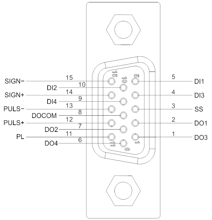
Figure 4-15 VD2F and VD2L servo drive control input and output pin distribution
| Pin number | Signal name | Pin number | Signal name | Pin number | Signal name |
|---|---|---|---|---|---|
| 1 | DO3 | 6 | DO4 | 11 | PL |
| 2 | DO1 | 7 | DO2 | 12 | PULS+ |
| 3 | SS | 8 | DOCOM | 13 | PULS- |
| 4 | DI3 | 9 | DI4 | 14 | SIGN+ |
| 5 | DI1 | 10 | DI2 | 15 | SIGN- |
Table 4-19 CN2 interface definition of VD2F and VD2L servo drive
Wiring diagram
VD2A, VD2B and VD2C servo drive

Figure 4-16 Wiring diagram of each mode
VD2-0xxSA1H servo drive

Figure 4-17 Wiring diagram of each mode
VD2F servo drive

Figure 4-18 Position pulse mode wiring
VD2L servo drive
 Figure 4-19 Position pulse mode wiring |
✎Note: Please refer to "4.4.1 Table 4-19 CN2 interface definition of VD2F and VD2L servo drive" for the pin numbers in the figure.
Position instruction input signal
| Signal name | VD2A and VD2B pin number | VD2F pin number | Function |
|---|---|---|---|
| PULS+ | 43 | 12 | Low-speed pulse input modes: differential input, open collector. There are three types of input pulse:
|
| PULS- | 42 | 13 | |
| SIGN+ | 41 | 14 | |
| SIGN- | 40 | 15 | |
| PL | 44 | 11 | External power input interface for instruction pulse. |
Table 4-20 Position instruction signal description
The instruction pulse and sign output circuit on the host device side can be selected from differential output or open collector output. The maximum input frequency is shown in the table.
| Pulse method | Difference | Open collector |
|---|---|---|
| Maximum frequency | 500KHz | 200KHz |
Differential input
The connection of differential input is shown in Figure 4-9

Figure 4-20 VD2A VD2B and VD2C servo drive differential input connection

Figure 4-21 VD2F and VD2L servo drive differential input connection
Open collector input
- Open collector input connection

Figure 4-22 VD2A, VD2B and VD2C servo drive open collector input connection

Figure 4-23 VD2F and VD2L servo drive open collector input connection
- NPN and PNP wiring
|
|
| NPN | PNP |
| Figure 4-24 Triode Wiring | |


Analog input signal
The analog input signal is only supported by VD2A, VD2B and VD2C servo drives.
| Pin number | Signal name | Function |
|---|---|---|
| 32 | AI_1+ | AI_1 analog input signal, resolution 12-bit. Input voltage range: -10V to +10V. |
| 33 | AI_1- | |
| 2 | AI_2+ | AI_2 analog input signal, resolution 12-bit. Input voltage range: -10V to +10V. |
| 3 | AI_2- | |
| 17 | GND | Analog input signal ground. |
| 34 | GND |
Table 4-21 Analog input signal description

Figure 4-25 Analog input wiring
Digital input&output signals
VD2A, VD2B and VD2C servo drives
| Pin number | Signal name | Default function |
|---|---|---|
| 9 | DI1 | Servo enable |
| 10 | DI2 | Faults and alarms clearance |
| 11 | DI3 | Forward drive prohibited |
| 12 | DI4 | Reverse drive prohibited |
| 23 | DI5 | Inverted instruction |
| 24 | DI6 | Instruction pulse prohibited input |
| 25 | DI7 | Not used |
| 26 | DI8 | Not used |
| 8 | SS | Power input 24V |
| 4 | DO1- | Rotation detection |
| 5 | DO1+ | |
| 6 | DO2- | Faults signal |
| 7 | DO2+ | |
| 19 | DO3- | Servo is ready |
| 20 | DO3+ | |
| 21 | DO4- | Positioning completed |
| 22 | DO4+ |
Table 4-22 DI/DO signal description
Digital input circuit
- When the control device (HMI/PLC) is relay output

Figure 4-26 Relay output
- When the control device (HMI/PLC) is open collector output

Figure 4-27 Open collector output
Digital output circuit
- When the control device (HMI/PLC) is relay input

Figure 4-28 Relay input
- When the control device (HMI/PLC) is optocoupler input

Figure 4-29 Optocoupler input
VD2-0xxSA1H servo drives
| Pin number | Pin name | Default function |
|---|---|---|
| 9 | DI1 | Servo enable |
| 10 | DI2 | Fault and alarm clearance |
| 11 | DI3 | Forward drive prohibited |
| 12 | DI4 | Reverse drive prohibited |
| 23 | DI5 | Inverted command |
| 24 | DI6 | command pulse prohibited input |
| 25 | DI7 | Not used |
| 26 | DI8 | Not used |
| 8 | SS | Power input (24V) |
| 5 | DO1+ | Fault signal |
| 7 | DO2+ | Pulse frequency division output (Z phase) |
| 20 | DO3+ | Pulse frequency division output (A phase) |
| 22 | DO4+ | Pulse frequency division output (B phase) |
| 4/6/19/21/35 | DOCOM | DO Power Common (0V) |
| 37 | 24V+ | DO power input (24V) |
Table 4-23 DI/DO signal description
Digital output circuit
- When the control device(HMI/PLC) is relay input

Figure 4-30 Relay input
- When the control device (HMI/PLC) is optocoupler input

Figure 4-31 Optocoupler input
The digital output circuit wiring of VD2-0xxSA1H Servo Drive is different from that of VD2A and VD2F servo drives. VD2-0xxSA1H needs to be connected to external 24V DC power supply. (CN2_35 pin and CN2_37 pin are connected to COM0 and 24V+ of external 24V power supply respectively). If the access current is too large and the DOCOM line is relatively thin, servo drives need to access multiple DOCOM to achieve the shunt effect.
VD2F servo drive
| Pin number | Pin name | Default function |
|---|---|---|
| 5 | DI1 | Servo enable |
| 10 | DI2 | Faults and alarms clearance |
| 4 | DI3 | Forward drive prohibited |
| 9 | DI4 | Reverse drive prohibited |
| 3 | SS | Power input 24V |
| 2 | DO1 | Rotation detection |
| 7 | DO2 | Fault signal |
| 1 | DO3 | Servo is ready |
| 6 | DO4 | Positioning completed |
| 8 | DOCOM | Do common terminal |
Table 4-24 DI/DO signal description
Digital input circuit
- When the control device (HMI/PLC) is relay output

Figure 4-32 Relay output
- When the control device (HMI/PLC) is open collector output

Figure 4-33 Open collector output
Digital output circuit
- When the control device (HMI/PLC) is relay input

Figure 4-34 Relay output
- When the control device (HMI/PLC) is optocoupler input

Figure 4-35 Optocoupler input
Brake wiring
The brake is a mechanism that prevents the servo motor shaft from moving when the servo drive is in a non-running state, so that the motor remains in position lock so that the moving part of the machinery will not move due to self-weight or external force.
The brake input signal is no polar. You need to use 24V power. The standard wiring between brake signal BK and brake power is as below.

Figure 4-36 Brake wiring of VD2A, VD2B and VD2C
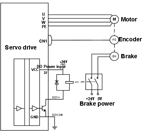
Figure 4-37 Brake wiring of VD2-0xxSA1H

Figure 4-38 Brake wiring of VD2F and VD2L
Communication signal wiring
Wecon VD2 series servo drive supports two communication modes: RS-422 and RS-485. The communication port is RJ45 socket. The exterior of communication terminal is shown in Figure 4-39

Figure 4-39 Pin number of an RJ45 socket
The communication modes supported by the driver communication ports are in the following table.
VD2 A&VD2 B&VD2 C | VD2F | ||
|---|---|---|---|
| Port | Communication mode | Port | Communication mode |
| CN3 | Only RS422 | CN3 | RS422, RS485 communication mode choose one of two. Set by function code P12-05 |
| CN5 | Only RS485 | CN4 | |
| CN6 | ✎Note: The CN3 and CN4 interfaces are physically connected and are actually the same communication interface. When P12-05 is set to 1, CN3 and CN4 use RS485 communication mode. If the value is set to 0, both use RS422 communication mode. | ||
| ✎Note: The CN5 and CN6 interfaces are physically connected and are actually the same communication interface. | |||
Table 4-25 Communication port communication mode table_1
| VD2L | |
| Interface | Communication node |
| USB | Only support servo upper computer |
| CN3 | Only support RS485 |
| CN4 | |
✎Note: The CN5 and CN6 interfaces are physically connected and are actually the same communication interface. | |
Communication port communication mode table_2
Communication connection with servo host computer (RS422)
Servo drives communicate with the host computer via RS422 communication. A USB to RS422 (RJ45 connector) cable is required for communication, and you need to equip it by yourselves.
- VD2A&VD2B
VD2A and VD2B servo drives communicate with the host computer via the CN3 interface by RS422 communication. Figure 4-36 and Figure 4-37 show the communication connections.
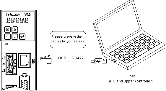
Figure 4-40 The Connection between VD2A drive and PC

Figure 4-41 The connection between VD2B and VD2C drive and PC
| CN3 | Pin | Name | Function description |
|---|---|---|---|
| 1 | RX- | Computer sends negative terminal (drive receives negative) |
| 2 | RX+ | Computer sends positive terminal (drive receives positive) | |
| 3 | TX- | Computer receives negative terminal (drive sends negative) | |
| 4 | GND | Ground terminal | |
| 5 | NC | Not used | |
| 6 | TX+ | Computer receives positive terminal (drive sends positive) | |
| 7 | NC | Not used | |
| 8 | NC | Not used |

Table 4-26 VD2A ,VD2B and VD2C pin definitions for CN3
- VD2F
VD2F servo drive communicates with the host computer via the CN3 or CN4 interface byRS422 communication. The communication diagrams of VD2F servo drive and host computer are shown in Figure 4-38.

Figure 4-42 The connection between VD2F drive and PC
| CN3&CN4 | Pin | Name | Function description |
|---|---|---|---|
 | 1 | RX- | Computer sends negative terminal (drive receives negative) |
| 2 | RX+ | Computer sends positive terminal (drive receives positive) | |
| 3 | TX- | Computer receives negative terminal (drive sends negative) | |
| 4 | GND | Ground terminal | |
| 5 | NC | Not used | |
| 6 | TX+ | Computer receives positive terminal (drive sends positive) | |
| 7 | NC | Not used | |
| 8 | NC | Not used |
Table 4-27 VD2F pin definitions for CN3/CN4 interfaces
VD2L
VD2L servo drive communicates with the host computer via the CN3 or CN4 interface byRS422 communication. The communication diagrams of VD2F servo drive and host computer are shown in Figure 4-43.

Figure 4-43 The connection between VD2L drive and PC
Communication connection with PLC and other device (RS485)
VD2A , VD2B and VD2C servo drives communicate with PLC and other devices for Modbus via CN5 or CN6 interface (located on the top of servo drive) by RS485 communication.
| CN5&CN6 | Pin | Name | Function description |
|---|---|---|---|
 | 1 | 485- | Computer sends negative terminal (drive receives negative) |
| 2 | 485+ | Computer sends positive terminal (drive receives positive) | |
| 3 | NC | Not used | |
| 4 | GND | Ground terminal | |
| 5 | GND | Ground terminal | |
| 6 | NC | Not used | |
| 7 | Reserved | Reserved | |
| 8 | GND | Ground terminal |
Table 4-28 VD2A, VD2B and VD2C pin definition of CN5/CN6 interface
VD2F and VD2L servo drives communicate with PLC and other devices for Modbus via CN3 or CN4 interface (located on the top of servo drive) by RS485 communication.
| CN3&CN4 | Pin | Name | Function description |
|---|---|---|---|
 | 1 | 485+ | Computer sends negative terminal (drive receives negative) |
| 2 | 485- | Computer sends positive terminal (drive receives positive) | |
| 3 | - | Computer receives negative terminal | |
| 4 | GND | Ground terminal | |
| 5 | - | Not used | |
| 6 | - | Computer receives positive terminal | |
| 7 | - | Not used | |
| 8 | - | Not used |
Table 4-29 VD2F and VD2L pin definition of CN3 , CN4 interfaces