09 Parameters
Group P00 Basic settings
| P00-01 | Parameter name | Setting method | Effective time | Default | Range | Category | Unit | |||||||||||||||||||||||||||||||||||||||
|---|---|---|---|---|---|---|---|---|---|---|---|---|---|---|---|---|---|---|---|---|---|---|---|---|---|---|---|---|---|---|---|---|---|---|---|---|---|---|---|---|---|---|---|---|---|---|
| Control mode | Shutdown setting | Effective immediately | 1 | 1 to 6 | Basic setting | - | ||||||||||||||||||||||||||||||||||||||||
Used to set the control mode of servo drive
When P00-01 is set to 4, 5 or 6, please refer to 6.5 Mixed control mode. ✎Note: VD2L drive P0-01 setting range: 1 to 3. Mix mode is not supported! | ||||||||||||||||||||||||||||||||||||||||||||||
| P00-04 | Parameter name | Setting method | Effective time | Default | Range | Category | Unit | |||||||||||||||
|---|---|---|---|---|---|---|---|---|---|---|---|---|---|---|---|---|---|---|---|---|---|---|
| Rotation direction | Shutdown setting | Effective immediately | 0 | 0 to 2 | Basic setting | - | ||||||||||||||||
Set the forward rotation direction of the motor when looking at the motor axis.
| ||||||||||||||||||||||

| P00-05 | Parameter name | Setting method | Effective time | Default | Range | Category | Unit | ||||||||||
| Servo OFF shutdown method | Shutdown setting | Effective immediately | 0 | 0 to 2 | Basic setting | - | |||||||||||
Set the forward rotation direction of the motor when looking at the motor axis.
| |||||||||||||||||
| P00-06 | Parameter name | Setting method | Effective time | Default | Range | Category | Unit | ||||||
| Servo OFF shutdown method | Shutdown setting | Effective immediately | 2 | 1 to 2 | Basic setting | - | |||||||
For setting the deceleration mode of the servo motor from rotation to stop and the state of the motor after stopping when the servo exceeds.
| |||||||||||||
| P00-09 | Parameter name | Setting method | Effective time | Default | Range | Category | Unit | ||||||||||||
| Braking resistor setting | Operation setting | Effective immediately | 0 | 0 to 3 | Basic setting | - | |||||||||||||
Used to set the way in which braking energy is absorbed and released.
| |||||||||||||||||||
| P00-10 | Parameter name | Setting method | Effective time | Default | Range | Category | Unit |
| External braking resistor value | Operation setting | Effective immediately | 50 | 0 to 65535 | Basic setting | Ω | |
Used to set the power of external braking resistor of servo drive. When the maximum braking energy calculated value is greater than the maximum braking energy absorbed by capacitor, and the braking power calculated value is greater than the built-in braking resistor power, external braking resistors are required. If the value of P00-10 is too large, Er.25 (too large braking resistor value) or Er.22 (main power supply is over voltage) will occur. When using an external braking resistor, the short wiring between C and D must be disconnected, and the external braking resistor should wiring between P+ and C. Please refer to 2.1.2 The composition of the servo drives. | |||||||
| P00-11 | Parameter name | Setting method | Effective time | Default | Range | Category | Unit |
| External braking resistor power | Operation setting | Effective immediately | 100 | 0 to 65535 | Basic setting | W | |
| Used to set resistor value of external braking resistor of servo drive. The power of external braking resistor (P00-11) can not less than the braking resistance power calculation value. | |||||||
| P00-12 | Parameter name | Setting method | Effective time | Default | Range | Category | Unit | ||||||||||||||||
Position pulse type selection | Operation setting | Power-on again | 0 | 0 to 5 | Position mode | - | |||||||||||||||||
In position control mode, when position instruction source is pulse instruction (P01-06=0) , input pulse pattern.
✎Note: VD2F and VD2L series drivers do not support the pulse form of CW/CCW! The P0-12 parameter setting range of VD2F and VD2L: 0, 2, 3, 5. | |||||||||||||||||||||||
| P00-14 | Parameter name | Setting method | Effective time | Default | Range | Category | Unit | ||||||||||||||||||||||||||||||||||||||||||||||||||||||||
Position pulse anti-interference level | Operation setting | Power-on again | 3 | 0 to 9 | Position mode | - | |||||||||||||||||||||||||||||||||||||||||||||||||||||||||
In position control mode, filter the input pulse. The larger the P00-14 setting value, the greater the filter depth. ✎Note: P0-14 filtering time of the VD2L series drive is not consistent with that of other VD2 series models.
| |||||||||||||||||||||||||||||||||||||||||||||||||||||||||||||||
| P00-16 | Parameter name | Setting method | Effective time | Default | Range | Category | Unit |
| Number of instruction pulses per turn of motor | Shutdown setting | Effective immediately | 10000 | 0 to 131072 | Position mode | Pulse instruction unit | |
| Used to set the number of instruction pulses required for per turn of motor | |||||||
| P00-17 | Parameter name | Setting method | Effective time | Default | Range | Category | Unit |
Electronic gear 1 numerator | Operation setting | Effective immediately | 1 | 0 to 4294967294 | Position mode | - | |
Used to set the numerator of the first group electronic gear for position instruction. This function code is only valid when P00-16=0. ✎Note: The setting range of VD2L is inconsistent with other models of VD2 series as follows: 1 to 2147483647. | |||||||
| P00-18 | Parameter name | Setting method | Effective time | Default | Range | Category | Unit |
Electronic gear 1 denominator | Operation setting | Effective immediately | 1 | 1 to 4294967294 | Position mode | - | |
Used to set the numerator of the first group electronic gear for position instruction. This function code is only valid when P00-16=0. ✎Note: The setting range of VD2L is inconsistent with other models of VD2 series as follows: 1 to 2147483647. | |||||||
| P00-19 | Parameter name | Setting method | Effective time | Default | Range | Category | Unit |
Electronic gear 2 numerator | Operation setting | Effective immediately | 1 | 0 to 4294967294 | Position mode | - | |
Used to set the numerator of the second group electronic gear for position instruction. This function code is only valid when P00-16=0. ✎Note: The setting range of VD2L is inconsistent with other models of VD2 series as follows: 1 to 2147483647. | |||||||
| P00-20 | Parameter name | Setting method | Effective time | Default | Range | Category | Unit |
Electronic gear 2 denominator | Operation setting | Effective immediately | 1 | 0 to 4294967294 | Position mode | - | |
Used to set the numerator of the second group electronic gear for position instruction. This function code is only valid when P00-16=0. ✎Note: The setting range of VD2L is inconsistent with other models of VD2 series as follows: 1 to 2147483647. | |||||||
P00-21 ☆ | Parameter name | Setting method | Effective time | Default | Range | Category | Unit | ||||||||||||||||
| Pulse frequency division output direction | Operation setting | Power-on again | 0 | 0 to 1 | Position mode | - | |||||||||||||||||
Used to set the pulse frequency division output direction. Since the pulse-division output of VD2L is not in CW/CCW from, but in+ direction form. This is a description of the function of all VD2 series modes except the VD2L model.
| |||||||||||||||||||||||
P00-22 ☆ | Parameter name | Setting method | Effective time | Default | Range | Category | Unit |
| The number of output pulses per turn of motor | Operation setting | Power-on again | 2500 | 0 to 2500 | Position mode | - | |
✎Note: When the motor rotates one circle, phase A and B can output up to 2500 pulses respectively. The upper receiving device needs to support 4 times frequency analysis to obtain 10000 pulses. | |||||||
“☆” indicates that the VD2F servo drive does not support this function code.
P00-23 ☆ | Parameter name | Setting method | Effective time | Default | Range | Category | Unit | ||||||
| Z pulse output OZ polarity | Operation setting | Power-on again | 0 | 0 to 1 | Position mode | - | |||||||
Used to set the level logic of Z pulse
| |||||||||||||
| P00-24 | Parameter name | Setting method | Effective time | Default | Set range | Application category | Unit |
| Z pulse output width | Operation setting | Power on again | 3 | 1 to 200 | Position mode | ms | |
Set Z pulse output width: 1: Pulse width 1ms 2: Pulse width 2ms …… 200: Pulse width 200ms ✎Note: This function code is only supported by VD2F series and Vd2L series V1.02 firmware models! | |||||||
| P00-25 | Parameter name | Setting method | Effective time | Default | Range | Category | Unit |
| Position deviation limit | Shutdown setting | Effective immediately | 60000 | 0 to 2147483646 | Position mode | Equivalent pulse unit | |
Used to set position deviation limit value. When the actual deviation of motor exceeds the setting value of this function code, Er.36 would occurs (position deviation is too large). When the function code is set to 0, positional bias is ignored. | |||||||
P00-27 ☆ | Parameter name | Setting method | Effective time | Default | Range | Category | Unit |
| Pulse output frequency division numerator | Operation setting | Power-on again | 1 | 1 to 2500 | Position mode | - | |
| Orthogonal encoded output (numerator/denominator) for setting the numerator of the frequency division pulse output. (This function code is valid when P00-22=0 and the pulse output frequency division numerator value is less than the pulse output frequency division denominator value. | |||||||
P00-28 ☆ | Parameter name | Setting method | Effective time | Default | Range | Category | Unit |
| Pulse output frequency division denominator | Operation setting | Power-on again | 1 | 1 to 2500 | Position mode | - | |
| Orthogonal encoded output (numerator/denominator). Used to set pulse output frequency division denominator. (When P00-22=0, and the pulse output frequency division denominator value is greater than the pulse output frequency division numerator value, this function code is valid) | |||||||
☆: Indicates that VD2F servo drive does not support this function code
〇: Indicates that VD2F servo drive does not support this function code
★: Indicates that VD2F and VD2L servo drives do not support this function code
| P00-29 | Parameter name | Setting method | Effective time | Default | Range | Category | Unit |
| The number of equivalent position units in one circle | Shutdown setting | Effective immediately | 10000 | 0 to 131072 | Position mode | - | |
| The equivalent position unit of one circle of the motor | |||||||
| P00-30 | Parameter name | Setting method | Effective time | Default | Range | Category | Unit | |||||||||||||||
| Shielded multi-turn absolute encoder battery failure | Operation setting | Power-on again | 0 | 0 to 3 | Basic setting | - | ||||||||||||||||
Used to set multi-turn absolute encoder battery fault alarm setting function. (VD2-SA V1.13 firmware added)
| ||||||||||||||||||||||
| P00-31 | Parameter name | Setting method | Effective time | Default | Range | Category | Unit |
| Encoder read-write check abnormal frequency | Operation setting | Effective immediately | 20 | 0 to 100 | Basic setting | - | |
Encoder read and write check abnormal frequency too high alarm threshold setting. 0: No alarm; Other values: above this setpoint, report A-93. | |||||||
Group P01 Control parameters
| P01-01 | Parameter name | Setting method | Effective time | Default | Range | Category | Unit | |||||||||
| Speed instruction source | Shutdown setting | Power-on again | 0 | 0 to 1 | Speed mode | - | ||||||||||
Select speed instruction source
“*” indicates that the VD2F and VD2L servo drives do not support this function code. | ||||||||||||||||
| P01-02 | Parameter name | Setting method | Effective time | Default | Range | Category | Unit |
| Internal speed instruction 0 | Operation setting | Effective immediately | 0 | -6000 to 6000 | Speed mode | ||
| rpm | |||||||
| When the servo driver is in speed control mode, it is used to set the rotational speed value of internal speed command 0. This function code is only valid when (P01-01=0). | |||||||
| P01-03 | Parameter name | Setting method | Effective time | Default | Range | Category | Unit |
| Acceleration time | Operation setting | Effective immediately | 50 | 0 to 65535 | Speed mode | ms | |
The time that the speed instruction accelerates from 0 to 1000 rpm. Please refer to 6.3.2 Acceleration and deceleration time setting | |||||||
| P01-04 | Parameter name | Setting method | Effective time | Default | Range | Category | Unit |
| deceleration time | Operation setting | Effective immediately | 50 | 0 to 65535 | Speed mode | ms | |
The time that the speed instruction decelerates from 1000 rpm to 0. Please refer to 6.3.2 Acceleration and deceleration time setting | |||||||
| P01-05 | Parameter name | Setting method | Effective time | Default | Range | Category | Unit |
| Shutdown deceleration time | Shutdown setting | Effective immediately | 50 | 0 to 65535 | - | ms | |
| The time for the speed command to decelerate from 1000rpm to 0 | |||||||
| P01-06 | Parameter name | Setting method | Effective time | Default | Range | Category | Unit | |||||||||
| Position instruction source | Operation setting | Effective immediately | 0 | 0 to 1 | - | - | ||||||||||
Used to select position instruction source when servo drive is in position control mode.
| ||||||||||||||||
| P01-07 | Parameter name | Setting method | Effective time | Default | Range | Category | Unit | |||||||||
Torque instruction source | Shutdown setting | Effective immediately | 0 | 0 to 1 | Torque mode | - | ||||||||||
Used to select torque instruction source when servo drive is in torque control mode.
“*” indicates that the VD2F and VD2L servo drives do not support this instruction source. | ||||||||||||||||
| P01-08 | Parameter name | Setting method | Effective time | Default | Range | Category | Unit | |||||||||||||||
| Torque instruction keyboard setting value | Operation setting | Effective immediately | 0 | -3000 to 3000 | Torque mode | 0.1% | ||||||||||||||||
| Used to set the required torque instruction value when P01-07 is set to 0 (internal torque instruction). | ||||||||||||||||||||||
| P01-09 | Parameter name | Setting method | Effective time | Default | Range | Category | Unit | |||||||||||||||
| Speed limit source in torque mode | Shutdown setting | Effective immediately | 0 | 0 to 1 | Torque mode | - | ||||||||||||||||
Used to set speed limit source when servo drive is in torque control mode.
“*” indicates that the VD2F and VD2L servo drives do not support this instruction source. | ||||||||||||||||||||||
| P01-10 | Parameter name | Setting method | Effective time | Default | Range | Category | Unit |
| Maximum speed threshold | Operation setting | Effective immediately | 3600 | 0 to 8000 | Protection and restriction | rpm | |
| Used to set the maximum speed limit value. If the actual speed of motor exceeds this value, Er.32 would occur (Exceed the maximum speed of motor). | |||||||
| P01-11 | Parameter name | Setting method | Effective time | Default | Range | Category | Unit |
| Warning speed threshold | Operation setting | Effective immediately | 3300 | 0 to 8000 | Protection and restriction | rpm | |
| Used to set the limit value of maximum speed. If the actual speed of motor exceeds this value, A-81 would occur (Exceed the maximum speed of motor). | |||||||
| P01-12 | Parameter name | Setting method | Effective time | Default | Range | Category | Unit |
| Forward speed threshold | Operation setting | Effective immediately | 3000 | 0 to 5000 | Protection and restriction | rpm | |
| Used to set the limit value of forward speed | |||||||
| P01-13 | Parameter name | Setting method | Effective time | Default | Range | Category | Unit |
| Reverse speed threshold | Operation setting | Effective immediately | 3000 | 0 to 6000 | Protection and restriction | rpm | |
| Used to set the limit value of reverse speed | |||||||
| P01-14 | Parameter name | Setting method | Effective time | Default | Range | Category | Unit | |||||||||
| Torque limit source | Shutdown setting | Effective immediately | 0 | 0 to 1 | Protection and restriction | - | ||||||||||
Used to select torque instruction source when servo drive is in torque control mode.
| ||||||||||||||||
| P01-15 | Parameter name | Setting method | Effective time | Default | Range | Category | Unit |
Forward torque limit | Operation setting | Effective immediately | 3000 | 0 to 3000 | Protection and restriction | 0.1% | |
| Used to set the limit value of forward speed | |||||||
| P01-16 | Parameter name | Setting method | Effective time | Default | Range | Category | Unit |
Reverse torque limit | Operation setting | Effective immediately | 3000 | 0 to 3000 | Protection and restriction | 0.1% | |
When P01-14 is set to 0 (internal) , the setting value of this function code is reverse torque limit value. If the value of P01-15 and P01-16 is set too small, the servo motor may be insufficient torque phenomenon when performing acceleration and deceleration movements. Please refer to 6.4.3 Torque instruction limit. | |||||||
| P01-17 | Parameter name | Setting method | Effective time | Default | Range | Category | Unit |
| Forward speed limit in torque mode | Operation setting | Effective immediately | 3000 | 0 to 6000 | Protection and restriction | rpm | |
| Used to set forward speed limit value in torque control mode. Please refer to 6.4.4 Speed limit in torque mode | |||||||
| P01-18 | Parameter name | Setting method | Effective time | Default | Range | Category | Unit |
| Reverse speed limit in torque mode | Operation setting | Effective immediately | 3000 | 0 to 6000 | Protection and restriction | rpm | |
| Used to set reverse speed limit value in torque control mode. Please refer to 6.4.4 Speed limit in torque mode | |||||||
| P01-19 | Parameter name | Setting method | Effective time | Default | Range | Category | Unit |
| Torque saturation timeout | Operation setting | Effective immediately | 3000 | 0 to 65535 | Protection and restriction | ms | |
When torque is limited by the setting value of P01-15 or P01-16, and exceeds the setting time, drive would report fault “torque saturation abnormal”. ✎Note: When the value of this function code is set to 0, the torque saturation timeout fault detection is not executed, and this fault is ignored. | |||||||
| P01-21 | Parameter name | Setting method | Effective time | Default | Range | Category | Unit | ||||||||||
| Zero-speed clamp function selection | Operation setting | Effective immediately | 0 | 0 to 3 | Speed mode | - | |||||||||||
Please refer to 6.3.4 Zero-speed clamp function
| |||||||||||||||||
| P01-22 | Parameter name | Setting method | Effective time | Default | Range | Category | Unit |
| Zero speed clamp speed threshold | Operation setting | Effective immediately | 20 | 0 to 5000 | Speed mode | rpm | |
| Used to set the speed threshold of zero-speed clamp function Please refer to 6.3.4 Zero-speed clamp function. | |||||||
| P01-23 | Parameter name | Setting method | Effective time | Default | Range | Category | Unit | ||||||||||||||||||||||||
Internal speed Instruction 1 | Operation setting | Effective immediately | 0 | -6000 to 6000 | Speed mode | rpm | |||||||||||||||||||||||||
Used to set the speed value of internal speed instruction 2. To use internal speed instruction 1 to 7, you need to set 3 DI terminals as DI function 13 (INSPD1, internal speed instruction 1) to (INSPD3, internal speed instruction 3). The switch of the internal speed instruction section is realized by controlling the DI terminal logic of the servo control device. The running instruction segment number is 3-bit binary number. The corresponding relationships between internal speed instruction 1 to 3 and running segment number are as below.
Please refer to 6.3.1 Speed instruction input setting | |||||||||||||||||||||||||||||||
P01-24 | Parameter name | Setting method | Effective time | Default | Range | Category | Unit |
Internal speed Instruction 2 | Operation setting | Effective immediately | 0 | -6000 to 6000 | Speed mode | rpm | |
| Used to set the speed value of internal speed instruction 2. | |||||||
| P01-25 | Parameter name | Setting method | Effective time | Default | Range | Category | Unit |
Internal speed Instruction 3 | Operation setting | Effective immediately | 0 | -6000 to 6000 | Speed mode | rpm | |
| Used to set the speed value of internal speed instruction 3. | |||||||
| P01-26 | Parameter name | Setting method | Effective time | Default | Range | Category | Unit |
Internal speed Instruction 4 | Operation setting | Effective immediately | 0 | -6000 to 6000 | Speed mode | rpm | |
| Used to set the speed value of internal speed instruction 4. | |||||||
| P01-27 | Parameter name | Setting method | Effective time | Default | Range | Category | Unit |
Internal speed Instruction 5 | Operation setting | Effective immediately | 0 | -6000 to 6000 | Speed mode | rpm | |
| Used to set the speed value of internal speed instruction 5. | |||||||
| P01-28 | Parameter name | Setting method | Effective time | Default | Range | Category | Unit |
Internal speed Instruction 6 | Operation setting | Effective immediately | 0 | -6000 to 6000 | Speed mode | rpm | |
| Used to set the speed value of internal speed instruction 6. | |||||||
| P01-29 | Parameter name | Setting method | Effective time | Default | Range | Category | Unit |
Internal speed Instruction 7 | Operation setting | Effective immediately | 0 | -6000 to 6000 | Speed mode | rpm | |
| Used to set the speed value of internal speed instruction 7. | |||||||
| P01-30 | Parameter name | Setting method | Effective time | Default | Range | Category | Unit |
| Delay from brake output ON to instruction reception | Operation setting | Effective immediately | 250 | 0 to 500 | - | rpm | |
| Set the delay time from the brake (BRK-OFF) output is ON to the servo drive allows to start receiving input instructions. When the brake output (BRK-OFF) is not allocated, this function code has no effect. Please refer to 6.1.8 Brake device. | |||||||
| P01-31 | Parameter name | Setting method | Effective time | Default | Range | Category | Unit |
| Stationary state. delay from the brake output is OFF to the motor is not energized | Operation setting | Effective immediately | 150 | 1 to 1000 | - | rpm | |
| When the motor is in a static state, set the delay time from the brake (BRK-OFF) output is OFF to the servo drive is in the non-powered state. When the brake output (BRK-OFF) is not allocated, this function code has no effect. Please refer to 6.1.8 Brake device. | |||||||
| P01-32 | Parameter name | Setting method | Effective time | Default | Range | Category | Unit |
| Rotation state, when the brake output is OFF, the speed threshold | Operation setting | Effective immediately | 30 | 0 to 3000 | - | rpm | |
| The motor is rotating, the motor speed threshold when the brake (BRK-OFF) is allowed to output OFF. When the brake output (BRK-OFF) is not allocated, this function code has no effect. Please refer to 6.1.8 Brake device. | |||||||
| P01-33 | Parameter name | Setting method | Effective time | Default | Range | Category | Unit |
| Rotation status, delay from servo enable OFF to brake output OFF | Operation setting | Effective immediately | 500 | 1 to 2000 | - | rpm | |
| The motor is rotating, the delay time from the brake (BRK-OFF) output OFF is allowed to the servo enable (S-ON) OFF. When the brake output (BRK-OFF) is not allocated, this function code has no effect. Please refer to 6.1.8 Brake device. | |||||||
| P01-37 | Parameter name | Setting method | Effective time | Default | Range | Category | Unit |
| JOG acceleration time | Operation setting | Effective immediately | 500 | 1 to 5000 | - | ms | |
The time for JOG instruction to accelerate from 0 to 1000rpm. ✎Note: VD2L does not support DI control JOG function for the time being, but the JOG function of VD2L supports P1-37 and P1-38 parameters. | |||||||
| P01-38 | Parameter name | Setting method | Effective time | Default | Range | Category | Unit |
| JOG deceleration time | Operation setting | Effective immediately | 500 | 1 to 5000 | - | ms | |
Time for a JOG instruction to decelerate from 100rpm to 0. ✎Note: VD2L does not support DI control JOG function for the time being, but JOG function of VD2L supports P1-37 and P1-38 parameters. | |||||||
| P01-39 〇 | Parameter name | Setting method | Effective time | Default | Range | Category | Unit | ||||||||||||
| Homing start mode | Stop setting | Effective immediately | 0 | 0 to 4 | - | - | |||||||||||||
| |||||||||||||||||||
| P01-40〇 | Parameter name | Setting method | Effective time | Default | Range | Category | Unit |
| Homing mode | Stop setting | Effective immediately | 0 | 0 to 35 | - | - | |
Homing mode. Please refer to the introduction of homing mode in the technical manual for details. ✎Note: VD2 disabled the 4 homing modes: 15, 16, 31 and 32. | |||||||
| P01-41〇 | Parameter name | Setting method | Effective time | Default | Range | Category | Unit |
| High speed search homing signal speed | Operation setting | Effective immediately | 600 | 1 to 3000 | - | rpm | |
High-speed search deceleration point signal velocity in homing mode. | |||||||
P01-42〇 | Parameter name | Setting method | Effective time | Default | Range | Category | Unit |
| Low-speed search homing signal speed | Operation setting | Effective immediately | 60 | 1 to 300 | - | rpm | |
Low-speed search origin signal velocity in homing mode. | |||||||
| P01-43〇 | Parameter name | Setting method | Effective time | Default | Range | Category | Unit |
| Homing acceleration and deceleration time | Operation setting | Effective immediately | 50 | 1 to 1000 | - | ms | |
Acceleration and deceleration time in homing mode Time for speed acceleration from 0 to 1000rpm | |||||||
| P01-44〇 | Parameter name | Setting method | Effective time | Default | Range | Category | Unit |
| Homing timeout limit time | Operation setting | Effective immediately | 65535 | 100 to 65535 | - | ms | |
Homing timeout limited time | |||||||
☆: Indicates that VD2F servo drive does not support this function code
〇: Indicates that VD2L servo drive does not support this function code
★: Indicates that VD2F and VD2L servo drives do not support this function code
Group P02 Gain adjustment
| P02-01 | Parameter name | Setting method | Effective time | Default | Range | Category | Unit |
| 1st position loop gain | Operation setting | Effective immediately | 232 | 0 to 6200 | Gain control | 0.1Hz | |
| Set the proportional gain of the 1st position loop to determine the responsiveness of position control system. | |||||||
| P02-02 | Parameter name | Setting method | Effective time | Default | Range | Category | Unit |
| 1st speed loop gain | Operation setting | Effective immediately | 200 | 0 to 35000 | Gain control | 0.1Hz | |
| Set the proportional gain of the 1st speed loop to determine the responsiveness of speed loop. | |||||||
| P02-03 | Parameter name | Setting method | Effective time | Default | Range | Category | Unit |
| 1st speed loop integral time constant | Operation setting | Effective immediately | 210 | 10 to 65535 | Gain control | 0.1ms | |
| Set the 1st speed loop integral constant. The smaller the set value, the stronger the integral effect. | |||||||
| P02-04 | Parameter name | Setting method | Effective time | Default | Range | Category | Unit |
| 2nd position loop gain | Operation setting | Effective immediately | 35 | 0 to 6200 | Gain control | 0.1Hz | |
| Set the proportional gain of the 2nd position loop to determine the responsiveness of position control system. | |||||||
| P02-05 | Parameter name | Setting method | Effective time | Default | Range | Category | Unit |
| 2nd speed loop gain | Operation setting | Effective immediately | 65 | 0 to 35000 | Gain control | 0.1Hz | |
| Set the proportional gain of the 2nd speed loop to determine the responsiveness of speed loop. | |||||||
| P02-06 | Parameter name | Setting method | Effective time | Default | Range | Category | Unit |
| 2nd speed loop integral time constant | Operation setting | Effective immediately | 1000 | 10 to 65535 | Gain control | 0.1ms | |
| Set the 2nd speed loop integral constant. The smaller the set value, the stronger the integral effect. | |||||||
| P02-07 | Parameter name | Setting method | Effective time | Default | Range | Category | Unit | ||||||
| 2nd gain switching mode | Operation setting | Effective immediately | 1 | 0 to 1 | Gain control | - | |||||||
Used to set the 2nd gain switching mode.
| |||||||||||||
| P02-08 | Parameter name | Setting method | Effective time | Default | Range | Category | Unit | ||||||||||||||||||||||||||||||||||||||||||||||||||||||||||||||||||||||||||||||||||||||||||||||||||||||||||||||||||||||||||||||||
| Gain switching condition selection | Operation setting | Effective immediately | 0 | 0 to 10 | Gain control | ||||||||||||||||||||||||||||||||||||||||||||||||||||||||||||||||||||||||||||||||||||||||||||||||||||||||||||||||||||||||||||||||||
Set the conditions for gain switching.
| |||||||||||||||||||||||||||||||||||||||||||||||||||||||||||||||||||||||||||||||||||||||||||||||||||||||||||||||||||||||||||||||||||||||
| P02-13 | Parameter name | Setting method | Effective time | Default | Range | Category | Unit |
| Delay Time for Gain Switching | Operation setting | Effective immediately | 20 | 0 to 10000 | Gain control | 0.1ms | |
The duration of the switching condition required for the second gain to switch back to the first gain.
✎Note: This parameter is only valid when the second gain is switched back to the first gain. | |||||||

| P02-14 | Parameter name | Setting method | Effective time | Default | Range | Category | Unit |
| Gain switching grade | Operation setting | Effective immediately | 50 | 0 to 20000 | Gain control | According to the switching conditions | |
Set the grade of the gain condition. The generation of the actual switching action is affected by the two conditions of grade and hysteresis.
| |||||||
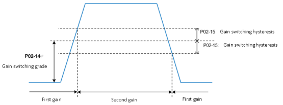
| P02-15 | Parameter name | Setting method | Effective time | Default | Range | Category | Unit |
| Gain switching hysteresis | Operation setting | Effective immediately | 20 | 0 to 20000 | Gain control | According to the switching conditions | |
Set the hysteresis to meet the gain switching condition.
| |||||||

| P02-16 | Parameter name | Setting method | Effective time | Default | Range | Category | Unit |
| Position loop gain switching time | Operation setting | Effective immediately | 30 | 0 to 10000 | Gain control | 0.1ms | |
Set the time for switching from the first position loop (P02-01) to the second position loop (P02-04) in the position control mode.
If P02-04≤P02-01, then P02-16 is invalid, and the second gain is switched from the first gain immediately. | |||||||

| P02-20 | Parameter name | Setting method | Effective time | Default | Range | Category | Unit |
| Enable model tracking control function | Stop setting | Effective immediately | 0 | 0 to 1 | Gain control | ||
Set 1 to enable the model tracking control function. | |||||||
| P02-21 | Parameter name | Setting method | Effective time | Default | Range | Category | Unit |
| Model tracking control gain | Stop setting | Effective immediately | 1000 | 200 to 20000 | Gain control | 0.1/s | |
Increasing the model tracking control gain can improve the position response performance of the model loop. If the gain is too high, it may cause overshoot behavior. | |||||||
| P02-22 | Parameter name | Setting method | Effective time | Default | Range | Category | Unit |
| Model tracking control gain compensation | Shutdown setting | Effective immediately | 1000 | 500 to 2000 | Gain control | 0.10% | |
The gain compensation affects the damping ratio of the model loop, and the damping ratio becomes larger as the gain compensation becomes larger. | |||||||
| P02-23 | Parameter name | Setting method | Effective time | Default | Range | Category | Unit |
| Model tracking control forward rotation bias | Operation setting | Effective immediately | 1000 | 0 to 10000 | Gain control | 0.10% | |
Torque feedforward size in the positive direction under model tracking control. | |||||||
| P02-24 | Parameter name | Setting method | Effective time | Default | Range | Category | Unit |
| Model tracking control reverses rotation bias | Operation setting | Effective immediately | 1000 | 0 to 10000 | Gain control | 0.10% | |
Torque feedforward size in the reverse direction under model tracking control. | |||||||
| P02-25 | Parameter name | Setting method | Effective time | Default | Range | Category | Unit |
| Model tracking control speed feedforward compensation | Operation setting | Effective immediately | 1000 | 0 to 10000 | Gain control | 0.10% | |
The size of the speed feedforward under model tracking control. | |||||||
| P02-26 | Parameter name | Setting method | Effective time | Default | Range | Category | Unit |
| 2nd model tracking control gain | Stop setting | Effective immediately | 1000 | 200 to 20000 | Gain control | 0.10% | |
| Increasing the model tracking control gain can improve the position response performance of the model loop, but too high a gain may cause overshoot. | |||||||
| P02-27 | Parameter name | Setting method | Effective time | Default | Range | Category | Unit |
| 2nd model tracking control gain compensation | Stop setting | Effective immediately | 1000 | 500 to 2000 | Gain control | 0.10% | |
| Gain compensation affects the damping ratio of the model loop, and the damping ratio increases as the gain compensation increases. | |||||||
| P02-28 | Parameter name | Setting method | Effective time | Default | Range | Category | Unit |
| Model tracking vibration suppression 1 frequency A | Stop setting | Effective immediately | 500 | 10 to 2500 | Gain control | 0.10Hz |
| P02-29 | Parameter name | Setting method | Effective time | Default | Range | Category | Unit |
| Model tracking vibration suppression 1 frequency B | Stop setting | Effective immediately | 700 | 10 to 2500 | Gain control | 0.10Hz |
| P02-32 | Parameter name | Setting method | Effective time | Default | Range | Category | Unit |
| Friction compensation function enabled | Stop setting | Effective immediately | 0 | 0 to 1 | Gain control | - |
| P02-33 | Parameter name | Setting method | Effective time | Default | Range | Category | Unit |
| Friction compensation gain | Operation setting | Effective immediately | 100 | 10 to 2000 | Gain control | 0.10% |
| P02-34 | Parameter name | Setting method | Effective time | Default | Range | Category | Unit |
| 2nd friction compensation gain | Stop setting | Effective immediately | 100 | 10 to 1000 | Gain control | 0.01 |
| P02-35 | Parameter name | Setting method | Effective time | Default | Range | Category | Unit |
| Friction compensation coefficient | Stop setting | Effective immediately | 0 | 0 to 100 | Gain control | 0.01 |
| P02-36 | Parameter name | Setting method | Effective time | Default | Range | Category | Unit |
| Friction compensation gain correction | Stop setting | Effective immediately | 0 | -10000 to 10000 | Gain control | 0.10Hz |
| P02-37 | Parameter name | Setting method | Effective time | Default | Range | Category | Unit |
| Friction compensation gain correction | Stop setting | Effective immediately | 100 | 1 to 1000 | Gain control | 0.01 |
Group P03 Self-adjusting parameters
| P03-01 | Parameter name | Setting method | Effective time | Default | Range | Category | Unit |
| Load inertia ratio | Operation setting | Effective immediately | 300* | 100 to 10000 | Automatic parameter tuning | 0.01 | |
Set load inertia ratio: 0.00 to 100.00 times. “*” indicates that the factory defaults for different models may differ. | |||||||
| P03-02 | Parameter name | Setting method | Effective time | Default | Range | Category | Unit |
| Load rigidity grade selection | Operation setting | Effective immediately | 14* | 0 to 31 | Automatic parameter tuning | - | |
| Set the rigidity of servo system. The higher the value, the faster the response, but too high rigidity will cause vibration. “*” indicates that the factory defaults for different models may differ. | |||||||
| P03-03 | Parameter name | Setting method | Effective time | Default | Range | Category | Unit | ||||||||||||
| Self-adjusting mode selection | Operation setting | Effective immediately | 0 | 0 to 2 | Automatic parameter tuning | - | |||||||||||||
Different gain adjustment modes could be set, and the relevant gain parameters could be set manually or automatically set according to the rigidity level table.
| |||||||||||||||||||
| P03-04 | Parameter name | Setting method | Effective time | Default | Range | Category | Unit |
| Online inertia recognition sensitivity | Operation setting | Effective immediately | 0 | 0 to 2 | Automatic parameter tuning | - | |
| Not implemented yet. | |||||||
| P03-05 | Parameter name | Setting method | Effective time | Default | Range | Category | Unit |
| Number of circles Inertia recognition | Shutdown setting | Effective immediately | 2 | 1 to 20 | Automatic parameter tuning | Circle | |
| Offline load inertia recognition process, motor rotation number setting | |||||||
| P03-06 | Parameter name | Setting method | Effective time | Default | Range | Category | Unit |
Inertia recognition maximum speed | Shutdown setting | Effective immediately | 1000 | 300 to 2000 | Automatic parameter tuning | rpm | |
| Set the allowable maximum motor speed instruction in offline inertia recognition mode. The faster the speed during inertia recognition, the more accurate the recognition result will be. You are advised to keep the default value. | |||||||
| P03-07 〇 | Parameter name | Setting method | Effective time | Default | Range | Category | Unit | ||||||||
Parameter recognition rotation direction | Shutdown setting | Effective immediately | 0 | 0 to 2 | Automatic parameter tuning | - | |||||||||
Set parameter recognition rotation direction
| |||||||||||||||
| P03-08 | Parameter name | Setting method | Effective time | Default | Range | Category | Unit |
Parameter recognition waiting time | Shutdown setting | Effective immediately | 1000 | 300 to 10000 | Automatic parameter tuning | ms | |
| During offline inertia recognition, the time interval between two consecutive speed instructions | |||||||
☆: Indicates that VD2F servo drive does not support this function code
〇: Indicates that VD2F servo drive does not support this function code
★: Indicates that VD2F and VD2L servo drives do not support this function code
Group P04 Vibration suppression
| P04-01 | Parameter name | Setting method | Effective time | Default | Range | Category | Unit | ||||||
| Pulse instruction filtering method | Shutdown setting | Effective immediately | 0 | 0 to 1 | Position mode | - | |||||||
| |||||||||||||
| P04-02 | Parameter name | Setting method | Effective time | Default | Range | Category | Unit | ||||
| Position instruction first-order low-pass filtering time constant | Shutdown setting | Effective immediately | 0 | 0 to 1000 | Position mode | ms | |||||
Used to set position instructions first-order low-pass filtering time constant.
| |||||||||||


| P04-03 | Parameter name | Setting method | Effective time | Default | Range | Category | Unit | ||||
| Position instruction average filtering time constant | Shutdown setting | Effective immediately | 0 | 0 to 128 | Position mode | ms | |||||
Used to set average filtering time constant.
| |||||||||||


| P04-04 | Parameter name | Setting method | Effective time | Default | Range | Category | Unit |
| Torque filtering time constant | Operation setting | Effective immediately | 80 | 10 to 2500 | Vibration suppression | 0.01ms | |
| Used to set torque filtering time constant. When the function code P03-03(Self-adjustment mode selection) is set to 0, the parameter is automatically set by servo. Please refer to 6.4.2 Torque instruction filtering | |||||||
| P04-05 | Parameter name | Setting method | Effective time | Default | Range | Category | Unit |
| 1st notch filter frequency | Operation setting | Effective immediately | 300 | 250 to 5000 | Vibration suppression | Hz | |
Set the center frequency of the 1st notch filter. When the function code is set to 5000, the function of the notch filter is invalid. | |||||||
| P04-06 | Parameter name | Setting method | Effective time | Default | Range | Category | Unit |
| 1st notch filter depth | Operation setting | Effective immediately | 100 | 0 to100 | Vibration suppression | - | |
Set the notch filter depth grade (the ratio between input and output at the center frequency of the notch filter) The larger the set value of this function code is, the smaller the notch filter depth is, and the weaker the suppression effect of mechanical vibration is. However, setting too large could cause system instability. Please refer to 7.4.2 Notch filter | |||||||
| P04-07 | Parameter name | Setting method | Effective time | Default | Range | Category | Unit |
| 1st notch filter width | Operation setting | Effective immediately | 4 | 0 to 12 | Vibration suppression | - | |
| Set the notch filter width grade (the ratio between input and output at the center frequency of the notch filter) | |||||||
| P04-08 | Parameter name | Setting method | Effective time | Default | Range | Category | Unit |
| 2nd notch filter frequency | Operation setting | Effective immediately | 500 | 250 to 5000 | Vibration suppression | Hz | |
Set the center frequency of the 1st notch filter. When the function code is set to 5000, the function of the notch filter is invalid. | |||||||
| P04-09 | Parameter name | Setting method | Effective time | Default | Range | Category | Unit |
| 2nd notch filter depth | Operation setting | Effective immediately | 100 | 0 to 100 | Vibration suppression | - |
| P04-10
| Parameter name | Setting method | Effective time | Default | Range | Category | Unit |
| 2nd notch filter width | Operation setting | Effective immediately | 4 | 0 to 12 | Vibration suppression | - |
| P04-11 〇 | Parameter name | Setting method | Effective time | Default | Range | Category | Unit |
| Enable low-frequency vibration suppression function | Operation setting | Effective immediately | 0 | 0 to 1 | Vibration suppression | ||
When the function code is set to 1, enable the low-frequency vibration suppression function. | |||||||
P04-12 〇 | Parameter name | Setting method | Effective time | Default | Range | Category | Unit |
| Low-frequency vibration suppression frequency | Operation setting | Effective immediately | 800 | 10 to 2000 | Vibration suppression | 0.1HZ | |
Set the center frequency of the 1st notch filter. When the function code is set to 5000, the function of the notch filter is invalid. | |||||||
| P04-14 〇 | Parameter name | Setting method | Effective time | Default | Range | Category | Unit |
| Shutdown vibration detection amplitude | Operation setting | Effective immediately | 100 | 1 to 3000 | Vibration suppression | 0.001 | |
When the vibration amplitude is greater than detection amplitude ratio, the low-frequency vibration frequency can be recognized and updated to the U0-16 monitor quantity. The function code is set too large or too small to affect the recognition of the vibration frequency. | |||||||
| P04-18 〇 | Parameter name | Setting method | Effective time | Default | Range | Category | Unit |
| Speed feedback filtering time | Operation setting | Effective immediately | 40 | 20 to 1000 | Vibration suppression | 0.01ms | |
Wave filtering of the feedback speed of the encoder. When the filtering time is set large, it may cause the motor to vibrate. | |||||||
| P04-19 〇 | Parameter name | Setting method | Effective time | Default | Range | Category | Unit |
| Enable the type A suppression function | Operation setting | Effective immediately | 0 | 0 to 1 | Vibration suppression | ||
When the function code is set to 1, enable the type A suppression function. | |||||||
| P04-20 〇 | Parameter name | Setting method | Effective time | Default | Range | Category | Unit |
| Type A suppression frequency | Operation setting | Effective immediately | 1000 | 100 to 20000 | Vibration suppression | 0.1HZ | |
Set the frequency of Type A suppression. | |||||||
| P04-21 〇 | Parameter name | Setting method | Effective time | Default | Range | Category | Unit |
| Type A suppression gain correction | Operation setting | Effective immediately | 100 | 0 to 1000 | Vibration suppression | 0.01 | |
Correct the load inertia ratio size. | |||||||
| P04-22 〇 | Parameter name | Setting method | Effective time | Default | Range | Category | Unit |
| Type A suppression damping gain | Operation setting | Effective immediately | 0 | 0 to 500 | Vibration suppression | 0.01 | |
The type A rejection compensation value is gradually increased until the vibration is reduced to the acceptable range. | |||||||
| P04-23 〇 | Parameter name | Setting method | Effective time | Default | Range | Category | Unit |
| Type A suppression phase correction | Operation setting | Effective immediately | 200 | 0 to 900 | Vibration suppression | 0.1 degree | |
Type A suppression phase compensation. | |||||||
☆: Indicates that VD2F servo drive does not support this function code
〇: Indicates that VD2F servo drive does not support this function code
★: Indicates that VD2F and VD2L servo drives do not support this function code
Group P05 Signal input and output
| P05-01☆ | Parameter name | Setting method | Effective time | Default | Range | Category | Unit |
| AI_1 input bias | Operation setting | Effective immediately | 0 | -5000 to 5000 | Analog input | mV | |
Set AI_1 channel analog bias value
“☆” indicates that the VD2F servo drive does not support this function code. | |||||||

| P05-02☆ | Parameter name | Setting method | Effective time | Default | Range | Category | Unit |
| AI_1 input filter time constant | Operation setting | Effective immediately | 200 | 0 to 60000 | Analog input | 0.01ms | |
Set AI_1 channel input first-order low-pass filter time constant “☆” indicates that the VD2F servo drive does not support this function code. | |||||||
| P05-03☆ | Parameter name | Setting method | Effective time | Default | Range | Category | Unit |
| AI_1 dead zone | Operation setting | Effective immediately | 20 | 0 to 1000 | Analog input | mV | |
Set AI_1 channel analog quantity dead zone value. “Dead zone” is the input voltage interval when the sample voltage is 0.
“☆” indicates that the VD2F servo drive does not support this function code. | |||||||

☆: Indicates that VD2F servo drive does not support this function code
〇: Indicates that VD2F servo drive does not support this function code
★: Indicates that VD2F and VD2L servo drives do not support this function code
| P05-04☆ | Parameter name | Setting method | Effective time | Default | Range | Category | Unit |
| AI_1 zero drift | Operation setting | Effective immediately | 0 | -500 to 500 | Analog input | mV | |
Set the zero drift of AI_1 channel analog. “zero drift” is the sample voltage co voltage relative to GND when analog channel voltage is 0.
“☆” indicates that the VD2F servo drive does not support this function code. | |||||||

| P05-05☆ | Parameter name | Setting method | Effective time | Default | Range | Category | Unit |
| AI_2 input bias | Operation setting | Effective immediately | 0 | -5000 to 5000 | Analog input | mV | |
| “☆” indicates that the VD2F servo drive does not support this function code. | |||||||
| P05-06☆ | Parameter name | Setting method | Effective time | Default | Range | Category | Unit |
| AI_2 input filter time constant | Operation setting | Effective immediately | 200 | 0 to 60000 | Analog input | 0.01ms | |
| “☆” indicates that the VD2F servo drive does not support this function code. | |||||||
| P05-07☆ | Parameter name | Setting method | Effective time | Default | Range | Category | Unit |
| AI_2 dead zone | Operation setting | Effective immediately | 20 | 0 to 500 | Analog input | mV | |
| “☆” indicates that the VD2F servo drive does not support this function code. | |||||||
| P05-08☆ | Parameter name | Setting method | Effective time | Default | Range | Category | Unit |
| AI_2 zero drift | Operation setting | Effective immediately | 0 | -500 to 500 | Analog input | mV | |
| “☆” indicates that the VD2F servo drive does not support this function code. | |||||||
| P05-09☆ | Parameter name | Setting method | Effective time | Default | Range | Category | Unit | ||||||
| Analog 10V corresponds to the speed value | Shutdown setting | Effective immediately | 3000 | 100 to 4500 | Analog input | rpm | |||||||
Set the speed value corresponding to the analog 10V
Given speed = sampling voltage / 10 * (P05-09) ☆: Indicates that VD2F servo drive does not support this function code 〇: Indicates that VD2F servo drive does not support this function code ★: Indicates that VD2F and VD2L servo drives do not support this function code | |||||||||||||

| P05-10☆ | Parameter name | Setting method | Effective time | Default | Range | Category | Unit | ||||||
| Analog 10V corresponds to the torque value | Shutdown setting | Effective immediately | 1000 | 0 to 3000 | Analog input | 0.1% | |||||||
Set the torque value corresponding to the analog 10V
Given torque= sampling voltage / 10 * (P05-10) “☆” indicates that the VD2F servo drive does not support this function code. | |||||||||||||

| P05-11 | Parameter name | Setting method | Effective time | Default | Range | Category | Unit | ||||||||||||
| Positioning completion, positioning approach condition setting | Operation setting | Effective immediately | 0 | 0 to 4 | Position mode | - | |||||||||||||
Set the conditions of setting positioning completion and positioning approach. When servo is in position mode, and the absolute value of the positional deviation is within the range of P05-12 (positioning complete threshold) or P05-13 (positioning approach threshold), servo would output the positioning complete signal and positioning approach signal.
“☆” indicates that the VD2F servo drive does not support this function code. | |||||||||||||||||||
| P05-12 | Parameter name | Setting method | Effective time | Default | Range | Category | Unit |
| Positioning completion threshold | Operation setting | Effective immediately | 800 | 1 to 65535 | Position mode | Equivalent pulse unit | |
| Set the threshold of absolute value of position deviation when servo drive output positioning completion signal | |||||||
| P05-13 | Parameter name | Setting method | Effective time | Default | Range | Category | Unit |
| Positioning approach threshold | Operation setting | Effective immediately | 5000 | 1 to 65535 | Position mode | Equivalent pulse unit | |
| Set the threshold of absolute value of position deviation when servo drive output positioning approach signal | |||||||
| P05-14 | Parameter name | Setting method | Effective time | Default | Range | Category | Unit |
| Position detection window time | Operation setting | Effective immediately | 10 | 0 to 20000 | Position mode | ms | |
| Set the detection window time for positioning completion | |||||||
| P05-15 | Parameter name | Setting method | Effective time | Default | Range | Category | Unit |
| Positioning signal holding time | Operation setting | Effective immediately | 100 | 0 to 20000 | Position mode | ms | |
| Set the time for the signal to remain in effect after positioning when P05-11=3 (Positioning completion and positioning approach condition setting) | |||||||
| P05-16 | Parameter name | Setting method | Effective time | Default | Range | Category | Unit |
| Rotation detection speed threshold | Operation setting | Effective immediately | 20 | 0 to 1000 | Speed mode | rpm | |
| Set the speed threshold that triggers the motor rotation signal. The motor rotation signal (TGON) is used to confirm that the motor has rotated. Please refer to 6.3.5 Speed-related DO output function | |||||||
| P05-17 | Parameter name | Setting method | Effective time | Default | Range | Category | Unit |
| Speed consistent signal threshold | Operation setting | Effective immediately | 10 | 0 to 100 | Speed mode | rpm | |
| Set the speed threshold that triggers the motor speed consistent signal. The motor outputs speed consistent signal (V-COIN) indicates that the actual speed has reached the speed instruction setting value. Please refer to 6.3.5 Speed-related DO output function | |||||||
| P05-18 | Parameter name | Setting method | Effective time | Default | Range | Category | Unit |
| Speed approach signal threshold | Operation setting | Effective immediately | 100 | 10 to 6000 | Speed mode | rpm | |
| Set the speed threshold that triggers the motor speed approach signal. The motor outputs speed approach signal (V-NEAR) indicates that the actual speed has reached the expected value. Please refer to 6.3.5 Speed-related DO output function | |||||||
| P05-19 | Parameter name | Setting method | Effective time | Default | Range | Category | Unit |
| Zero speed output signal threshold | Operation setting | Effective immediately | 10 | 0 to 6000 | Speed mode | rpm | |
| Set the speed threshold that triggers the motor zero speed output signal. The motor outputs zero speed signal (ZSP) indicates that the actual speed is almost stationary. Please refer to 6.3.5 Speed-related DO output function | |||||||
| P05-20 | Parameter name | Setting method | Effective time | Default | Range | Category | Unit |
| Torque arrival threshold | Operation setting | Effective immediately | 100 | 0 to 300 | Torque mode | % | |
| Please refer to 6.4.5 Torque-related DO output functions | |||||||
| P05-21 | Parameter name | Setting method | Effective time | Default | Range | Category | Unit |
| Torque arrival hysteresis value | Operation setting | Effective immediately | 10 | 0 to 20 | Torque mode | % | |
| Please refer to 6.4.5 Torque-related DO output functions | |||||||
Group P06 DI/DO configuration
| P06-02 | Parameter name | Setting method | Effective time | Default | Range | Category | Unit | ||||||||||||||||||||||||||||||||||||||||||||||||||||||||||||||||||||||||
| DI_1 channel function selection | Operation setting | Power on again | 01 | 0 to 32 | DI/DO | - | |||||||||||||||||||||||||||||||||||||||||||||||||||||||||||||||||||||||||
Set DI functions corresponding to hardware DI_1. The related functions are as below.
If P06-02 is set to a value other than that in the table above, the DI port function is not required. The same DI channel function could not be allocated to multiple DI ports, otherwise servo drive will occur A-89 (DI port configuration duplication) | |||||||||||||||||||||||||||||||||||||||||||||||||||||||||||||||||||||||||||||||
| P06-03 | Parameter name | Setting method | Effective time | Default | Range | Category | Unit | |||||||||
| DI_1 channel logic selection | Operation setting | Effective immediately | 0 | 0 to 1 | DI/DO | - | ||||||||||
DI port input logic validity function selection
| ||||||||||||||||


| P06-04 | Parameter name | Setting method | Effective time | Default | Range | Category | Unit | ||||||
| DI_1 input source selection | Operation setting | Effective immediately | 0 | 0 to 1 | DI/DO | - | |||||||
Select the enabled DI_1 port type
| |||||||||||||
| P06-05 | Parameter name | Setting method | Effective time | Default | Range | Category | Unit |
| DI_2 channel function selection | Operation setting | Power on again | 2 | 0 to 32 | DI/DO | - |
| P06-06 | Parameter name | Setting method | Effective time | Default | Range | Category | Unit |
| DI_2 channel logic selection | Operation setting | Effective immediately | 0 | 0 to 1 | DI/DO | - |
| P06-07 | Parameter name | Setting method | Effective time | Default | Range | Category | Unit |
| DI_2 input source selection | Operation setting | Effective immediately | 0 | 0 to 1 | DI/DO | - |
| P06-08 | Parameter name | Setting method | Effective time | Default | Range | Category | Unit |
| DI_3 channel function selection | Operation setting | Power on again | 3 | 0 to 32 | DI/DO | - |
| P06-09 | Parameter name | Setting method | Effective time | Default | Range | Category | Unit |
| DI_3 channel logic selection | Operation setting | Effective immediately | 0 | 0 to 1 | DI/DO | - |
| P06-10 | Parameter name | Setting method | Effective time | Default | Range | Category | Unit |
| DI_3 input source selection | Operation setting | Effective immediately | 0 | 0 to 1 | DI/DO | - |
| P06-11 | Parameter name | Setting method | Effective time | Default | Range | Category | Unit |
| DI_4 channel function selection | Operation setting | Power on again | 4 | 0 to 32 | DI/DO | - |
| P06-12 | Parameter name | Setting method | Effective time | Default | Range | Category | Unit |
| DI_4 channel logic selection | Operation setting | Effective immediately | 0 | 0 to 1 | DI/DO | - |
| P06-13 | Parameter name | Setting method | Effective time | Default | Range | Category | Unit |
| DI_4 input source selection | Operation setting | Effective immediately | 0 | 0 to 1 | DI/DO | - |
| P06-14 ★ | Parameter name | Setting method | Effective time | Default | Range | Category | Unit |
| DI_5 channel function selection | Operation setting | Power on again | 7 | 0 to 32 | DI/DO | - |
| P06-15 ★ | Parameter name | Setting method | Effective time | Default | Range | Category | Unit |
| DI_5 channel logic selection | Operation setting | Effective immediately | 0 | 0 to 1 | DI/DO | - |
| P06-16 ★ | Parameter name | Setting method | Effective time | Default | Range | Category | Unit |
| DI_5 input source selection | Operation setting | Effective immediately | 0 | 0 to 1 | DI/DO | - |
| P06-17 ★ | Parameter name | Setting method | Effective time | Default | Range | Category | Unit |
| DI_6 channel function selection | Operation setting | Power on again | 11 | 0 to 32 | DI/DO | - |
| P06-18☆ | Parameter name | Setting method | Effective time | Default | Range | Category | Unit |
| DI_6 channel logic selection | Operation setting | Effective immediately | 0 | 0 to 1 | DI/DO | - |
| P06-19 ★ | Parameter name | Setting method | Effective time | Default | Range | Category | Unit |
| DI_6 input source selection | Operation setting | Effective immediately | 0 | 0 to 1 | DI/DO | - |
| P06-20 ★ | Parameter name | Setting method | Effective time | Default | Range | Category | Unit |
| DI_7 channel function selection | Operation setting | Power on again | 2 | 0 to 32 | DI/DO | - |
| P06-21 ★ | Parameter name | Setting method | Effective time | Default | Range | Category | Unit |
| DI_7 channel logic selection | Operation setting | Power on again | 0 | 0 to 1 | DI/DO | - |
| P06-22 ★ | Parameter name | Setting method | Effective time | Default | Range | Category | Unit |
| DI_7 input source selection | Operation setting | Effective immediately | 0 | 0 to 1 | DI/DO | - |
| P06-23 ★ | Parameter name | Setting method | Effective time | Default | Range | Category | Unit |
| DI_8 channel function selection | Operation setting | Power on again | 2 | 0 to 32 | DI/DO | - |
| P06-24 ★ | Parameter name | Setting method | Effective time | Default | Range | Category | Unit |
| DI_8 channel logic selection | Operation setting | Power on again | 0 | 0 to 1 | DI/DO | - |
| P06-25 ★ | Parameter name | Setting method | Effective time | Default | Range | Category | Unit |
| DI_8 input source selection | Operation setting | Effective immediately | 0 | 0 to 1 | DI/DO | - |
| P06-26 | Parameter name | Setting method | Effective time | Default | Range | Category | Unit | ||||||||||||||||||||||||||||||||||||||||||||||||
| DO_1 channel function selection | Operation setting | Effective immediately | 132 | 128 to 148 | DI/DO | - | |||||||||||||||||||||||||||||||||||||||||||||||||
Set DO functions corresponding to hardware DO_1. The related functions are as below.
If P06-26 is set to a value other than that in the preceding table, the DO port function is not required The same DO channel function could not be allocated to multiple DO ports, otherwise servo drive will occur A-90 (DO port configuration duplication) “✎1”: Use the function code BRK-OFF would be effective after power on again. “✎2”: ① Only VD2H, VD2L and VD2F support 143 function code. For VD2-0xxSA1G model, this function code is empty. 143 function code would be effective after power on again. ② Only for VD2-0xxSA1H model, DO_1 default function code is 130ALM (fault signal). Only for VD2-0xxSA1H model, DO_2, DO_3, DO_4 function code is 143 OZ (Z/A/B pulse output), these 3 channels correspond to the Z, A and B phase of the pulse output. ③ For VD2L-0xxSa1P model, DO_2, DO_3 and DO_4 function code is 143 OZ/A/B (Z pulse/pulse/direction output). These 2 channels corresponds to Z axis, pulse axis and direction axis. Currently, VD2L does not support 149 function code. ④ Currently, VD2L does not support 149 function code. For related content, please refer to [6.2.6 Collector pulse signal DO output function and VD2L pulse signal DO output function of VD2-0xxSA1H] | |||||||||||||||||||||||||||||||||||||||||||||||||||||||
| P06-27 | Parameter name | Setting method | Effective time | Default | Range | Category | Unit | ||||||
| DO_1 channel logic selection | Operation setting | Effective immediately | 0 | 0 to 1 | DI/DO | - | |||||||
DO Port input logic validity function selection.
| |||||||||||||
| P06-28 | Parameter name | Setting method | Effective time | Default | Range | Category | Unit |
| DO_2 channel function selection | Operation setting | Effective immediately | 130 | 128 to 149 | DI/DO | - |
| P06-29 | Parameter name | Setting method | Effective time | Default | Range | Category | Unit |
| DO_2 channel logic selection | Operation setting | Effective immediately | 0 | 0 to 1 | DI/DO | - |
| P06-30 | Parameter name | Setting method | Effective time | Default | Range | Category | Unit |
| DO_3 channel function selection | Operation setting | Effective immediately | 129 | 128 to 149 | DI/DO | - |
| P06-31 | Parameter name | Setting method | Effective time | Default | Range | Category | Unit |
| DO_3 channel logic selection | Operation setting | Effective immediately | 0 | 0 to 1 | DI/DO | - |
| P06-32 | Parameter name | Setting method | Effective time | Default | Range | Category | Unit |
| DO_4 channel function selection | Operation setting | Effective immediately | 134 | 128 to 149 | DI/DO | - |
| P06-33 | Parameter name | Setting method | Effective time | Default | Range | Category | Unit |
| DO_4 channel logic selection | Operation setting | Effective immediately | 0 | 0 to 1 | DI/DO | - |
Group P07 multi-segment position
| P07-01 | Parameter name | Setting method | Effective time | Default | Range | Category | Unit | ||||||||||||
| Multi-segment position operation mode | Shutdown setting | Effective immediately | 0 | 0 to 2 | - | - | |||||||||||||
When servo is in position mode, and P01-06 (position instruction source) =1, set the operation mode of multi-segment position
To use multi-segment position function, a DI port channel of servo drive should configured to function 20 (ENINPOS, internal multi-segment position enable signal), and the logic of the DI terminal valid should be confirmed. Please refer to Group P06 DI/DO configuration | |||||||||||||||||||
| P07-02 | Parameter name | Setting method | Effective time | Default | Range | Category | Unit | ||||||||||||||||||||||||||||||
Starting position number | Shutdown setting | Effective immediately | 1 | 1 to 16 | - | - | |||||||||||||||||||||||||||||||
Set the starting segment number in single running or cycle running. When P07-01≠2, the segment number automatic increment switching. When P07-01=2, 4 DI ports need be set to DI function 21 (INPOS1, internal multi-segment position segment selection 1 to INPOS4, internal multi-segment position segment selection 4 ), and the segment number is switched by the servo host computer to control the DI terminal logic. Multi-segment number is 4-bit binary number. The corresponding relations between internal multi-segment position segment selection and segment number are as below. If DI terminal logic is valid, the value of internal multi-segment position segment selection is 1, otherwise it is 0.
| |||||||||||||||||||||||||||||||||||||
| P07-03 | Parameter name | Setting method | Effective time | Default | Range | Category | Unit |
End position number | Shutdown setting | Effective immediately | 1 | 1 to 16 | - | - | |
Set the end segment number in single running or cycle running. When P07-01≠2, the segment number automatic increment switching. The switching sequence is: P07-02, ……, P07-03. | |||||||
| P07-04 | Parameter name | Setting method | Effective time | Default | Range | Category | Unit | |||||||||
Margin handling method | Shutdown setting | Effective immediately | 0 | 0 to 1 | - | - | ||||||||||
The starting segment number used for the servo drive will run when it resumes after pausing in multi-segment. “Pause” indicates that internal multi-segment position enable signal changes from valid to invalid.
Once paused during multi-segment position operation, the servo drive will abandon the unfinished position instructions in this segment and shutdown. Please refer to Margin handling method | ||||||||||||||||
| P07-05 | Parameter name | Setting method | Effective time | Default | Range | Category | Unit | |||||||||
| Displacement instruction type | Shutdown setting | Effective immediately | 0 | 0 to 1 | - | - | ||||||||||
Set the displacement instruction type of multi-segment position function. “Displacement instruction” is the sum of the displacement instructions over a period of time.
| ||||||||||||||||
| P07-06 | Parameter name | Setting method | Effective time | Default | Range | Category | Unit | ||||||
Waiting time unit | Shutdown setting | Effective immediately | 0 | 0 to 1 | - | - | |||||||
Set the waiting unit of multi-segment position function. “waiting time” is the interval between the end of this instruction and the start of the next instruction.
| |||||||||||||
| P07-09 | Parameter name | Setting method | Effective time | Default | Range | Category | Unit |
| The 1st segment displacement | Operation setting | Effective immediately | 10000 | -2147483647 to 2147483646 | - | - | |
| Set the 1st segment position displacement | |||||||
| P07-10 | Parameter name | Setting method | Effective time | Default | Range | Category | Unit |
| Maximum speed of the 1st segment displacement | Operation setting | Effective immediately | 100 | 1 to 6000 | - | rpm | |
| Set the maximum speed of the 1st position displacement. Maximum running speed refers to the speed the motor that is not in the process of acceleration and deceleration. If P07-09 (1st position displacement) is set too small, the actual speed of motor would be less than P07-10. | |||||||
| P07-11 | Parameter name | Setting method | Effective time | Default | Range | Category | Unit |
| Acceleration and deceleration time of the 1st segment displacement | Operation setting | Effective immediately | 100 | 1 to 65535 | - | ms | |
| Used to set the time when the motor in the multi-segment position is uniformly accelerated from 0rpm to the P07-10 (maximum speed of the 1st segment displacement) in the multi-segment position. | |||||||
| P07-12 | Parameter name | Setting method | Effective time | Default | Range | Category | Unit |
| Waiting time after completion of the 1st segment displacement | Operation setting | Effective immediately | 100 | 1 to 65535 | - | Set by P07-06 | |
| Used to set the waiting time before running the next segment displacement after the multi-segment position of the 1st displacement is completed | |||||||
| P07-13 | Parameter name | Setting method | Effective time | Default | Range | Category | Unit |
The 2nd segment displacement | Operation setting | Effective immediately | 10000 | -2147483647 to 2147483646 | - | - |
| P07-14 | Parameter name | Setting method | Effective time | Default | Range | Category | Unit |
| Maximum speed of the 2nd segment displacement | Operation setting | Effective immediately | 100 | 1 to 6000 | - | rpm |
| P07-15 | Parameter name | Setting method | Effective time | Default | Range | Category | Unit |
| Acceleration and deceleration time of the 2nd segment displacement | Operation setting | Effective immediately | 100 | 1 to 65535 | - | ms |
| P07-16 | Parameter name | Setting method | Effective time | Default | Range | Category | Unit |
| Waiting time after completion of the 2nd segment displacement | Operation setting | Effective immediately | 100 | 1 to 65535 | - | Set by P07-06 |
| P07-17 | Parameter name | Setting method | Effective time | Default | Range | Category | Unit |
The 3rd segment displacement | Operation setting | Effective immediately | 10000 | -2147483647 to 2147483646 | - | - |
| P07-18 | Parameter name | Setting method | Effective time | Default | Range | Category | Unit |
| Maximum speed of the 3rd segment displacement | Operation setting | Effective immediately | 100 | 1 to 6000 | - | rpm |
| P07-19 | Parameter name | Setting method | Effective time | Default | Range | Category | Unit |
| Acceleration and deceleration time of the 3rd segment displacement | Operation setting | Effective immediately | 100 | 1 to 65535 | - | ms |
| P07-20 | Parameter name | Setting method | Effective time | Default | Range | Category | Unit |
| Waiting time after completion of the 3rd segment displacement | Operation setting | Effective immediately | 100 | 1 to 65535 | - | Set by P07-06 |
| P07-21 | Parameter name | Setting method | Effective time | Default | Range | Category | Unit |
The 4th segment displacement | Operation setting | Effective immediately | 10000 | -2147483647 to 2147483646 | - | - |
| P07-22 | Parameter name | Setting method | Effective time | Default | Range | Category | Unit |
| Maximum speed of the 4th segment displacement | Operation setting | Effective immediately | 100 | 1 to 5000 | - | rpm |
| P07-23 | Parameter name | Setting method | Effective time | Default | Range | Category | Unit |
| Acceleration and deceleration time of the 4th segment displacement | Operation setting | Effective immediately | 100 | 1 to 65535 | - | ms |
| P07-24 | Parameter name | Setting method | Effective time | Default | Range | Category | Unit |
| Waiting time after completion of the 4th segment displacement | Operation setting | Effective immediately | 100 | 1 to 65535 | - | Set by P07-06 |
| P07-25 | Parameter name | Setting method | Effective time | Default | Range | Category | Unit |
The 5th segment displacement | Operation setting | Effective immediately | 10000 | -2147483647 to 2147483646 | - | - |
| P07-26 | Parameter name | Setting method | Effective time | Default | Range | Category | Unit |
| Maximum speed of the 5th segment displacement | Operation setting | Effective immediately | 100 | 1 to 6000 | - | rpm |
| P07-27 | Parameter name | Setting method | Effective time | Default | Range | Category | Unit |
| Acceleration and deceleration time of the 5th segment displacement | Operation setting | Effective immediately | 100 | 1 to 65535 | - | ms |
| P07-28 | Parameter name | Setting method | Effective time | Default | Range | Category | Unit |
| Waiting time after completion of the 5th segment displacement | Operation setting | Effective immediately | 100 | 1 to 65535 | - | Set by P07-06 |
| P07-29 | Parameter name | Setting method | Effective time | Default | Range | Category | Unit |
The 6th segment displacement | Operation setting | Effective immediately | 10000 | -2147483647 to 2147483646 | - | - |
| P07-30 | Parameter name | Setting method | Effective time | Default | Range | Category | Unit |
| Maximum speed of the 6th segment displacement | Operation setting | Effective immediately | 100 | 1 to 6000 | - | rpm |
| P07-31 | Parameter name | Setting method | Effective time | Default | Range | Category | Unit |
| Acceleration and deceleration time of the 6th segment displacement | Operation setting | Effective immediately | 100 | 1 to 65535 | - | ms |
| P07-32 | Parameter name | Setting method | Effective time | Default | Range | Category | Unit |
| Waiting time after completion of the 6th segment displacement | Operation setting | Effective immediately | 100 | 1 to 65535 | - | Set by P07-06 |
| P07-33 | Parameter name | Setting method | Effective time | Default | Range | Category | Unit |
The 7th segment displacement | Operation setting | Effective immediately | 10000 | -2147483647 to 2147483646 | - | - |
| P07-34 | Parameter name | Setting method | Effective time | Default | Range | Category | Unit |
| Maximum speed of the 7th segment displacement | Operation setting | Effective immediately | 100 | 1 to 6000 | - | rpm |
| P07-35 | Parameter name | Setting method | Effective time | Default | Range | Category | Unit |
| Acceleration and deceleration time of the 7th segment displacement | Operation setting | Effective immediately | 100 | 1 to 65535 | - | ms |
| P07-36 | Parameter name | Setting method | Effective time | Default | Range | Category | Unit |
| Waiting time after completion of the 7th segment displacement | Operation setting | Effective immediately | 100 | 1 to 65535 | - | Set by P07-06 |
| P07-37 | Parameter name | Setting method | Effective time | Default | Range | Category | Unit |
The 8th segment displacement | Operation setting | Effective immediately | 10000 | -2147483647 to 2147483646 | - | - |
| P07-38 | Parameter name | Setting method | Effective time | Default | Range | Category | Unit |
| Maximum speed of the 8th segment displacement | Operation setting | Effective immediately | 100 | 1 to 6000 | - | rpm |
| P07-39 | Parameter name | Setting method | Effective time | Default | Range | Category | Unit |
| Acceleration and deceleration time of the 8th segment displacement | Operation setting | Effective immediately | 100 | 1 to 65535 | - | ms |
| P07-40 | Parameter name | Setting method | Effective time | Default | Range | Category | Unit |
| Waiting time after completion of the 8th segment displacement | Operation setting | Effective immediately | 100 | 1 to 65535 | - | Set by P07-06 |
| P07-41 | Parameter name | Setting method | Effective time | Default | Range | Category | Unit |
The 9th segment displacement | Operation setting | Effective immediately | 10000 | -2147483647 to 2147483646 | - | - |
| P07-42 | Parameter name | Setting method | Effective time | Default | Range | Category | Unit |
| Maximum speed of the 9th segment displacement | Operation setting | Effective immediately | 100 | 1 to 6000 | - | rpm |
| P07-43 | Parameter name | Setting method | Effective time | Default | Range | Category | Unit |
| Acceleration and deceleration time of the 9th segment displacement | Operation setting | Effective immediately | 100 | 1 to 65535 | - | ms |
| P07-44 | Parameter name | Setting method | Effective time | Default | Range | Category | Unit |
| Waiting time after completion of the 9th segment displacement | Operation setting | Effective immediately | 100 | 1 to 65535 | - | Set by P07-06 |
| P07-45 | Parameter name | Setting method | Effective time | Default | Range | Category | Unit |
The 10th segment displacement | Operation setting | Effective immediately | 10000 | -2147483647 to 2147483646 | - | - |
| P07-46 | Parameter name | Setting method | Effective time | Default | Range | Category | Unit |
| Maximum speed of the 10th segment displacement | Operation setting | Effective immediately | 100 | 1 to 6000 | - | rpm |
| P07-47 | Parameter name | Setting method | Effective time | Default | Range | Category | Unit |
| Acceleration and deceleration time of the 10th segment displacement | Operation setting | Effective immediately | 100 | 1 to 65535 | - | ms |
| P07-48 | Parameter name | Setting method | Effective time | Default | Range | Category | Unit |
| Waiting time after completion of the 10th segment displacement | Operation setting | Effective immediately | 100 | 1 to 65535 | - | Set by P07-06 |
| P07-49 | Parameter name | Setting method | Effective time | Default | Range | Category | Unit |
The 11th segment displacement | Operation setting | Effective immediately | 10000 | -2147483647 to 2147483646 | - | - |
| P07-50 | Parameter name | Setting method | Effective time | Default | Range | Category | Unit |
| Maximum speed of the 11th segment displacement | Operation setting | Effective immediately | 100 | 1 to 6000 | - | rpm |
| P07-51 | Parameter name | Setting method | Effective time | Default | Range | Category | Unit |
| Acceleration and deceleration time of the 11th segment displacement | Operation setting | Effective immediately | 100 | 1 to 65535 | - | ms |
| P07-52 | Parameter name | Setting method | Effective time | Default | Range | Category | Unit |
| Waiting time after completion of the 11th segment displacement | Operation setting | Effective immediately | 100 | 1 to 65535 | - | Set by P07-06 |
| P07-53 | Parameter name | Setting method | Effective time | Default | Range | Category | Unit |
The 12th segment displacement | Operation setting | Effective immediately | 10000 | -2147483647 to 2147483646 | - | - |
| P07-54 | Parameter name | Setting method | Effective time | Default | Range | Category | Unit |
| Maximum speed of the 12th segment displacement | Operation setting | Effective immediately | 100 | 1 to 6000 | - | rpm |
| P07-55 | Parameter name | Setting method | Effective time | Default | Range | Category | Unit |
| Acceleration and deceleration time of the 12th segment displacement | Operation setting | Effective immediately | 100 | 1 to 65535 | - | ms |
| P07-56 | Parameter name | Setting method | Effective time | Default | Range | Category | Unit |
| Waiting time after completion of the 12th segment displacement | Operation setting | Effective immediately | 100 | 1 to 65535 | - | Set by P07-06 |
| P07-57 | Parameter name | Setting method | Effective time | Default | Range | Category | Unit |
The 13th segment displacement | Operation setting | Effective immediately | 10000 | -2147483647 to 2147483646 | - | - |
| P07-58 | Parameter name | Setting method | Effective time | Default | Range | Category | Unit |
| Maximum speed of the 13th segment displacement | Operation setting | Effective immediately | 100 | 1 to 6000 | - | rpm |
| P07-59 | Parameter name | Setting method | Effective time | Default | Range | Category | Unit |
| Acceleration and deceleration time of the 13th segment displacement | Operation setting | Effective immediately | 100 | 1 to 65535 | - | ms |
| P07-60 | Parameter name | Setting method | Effective time | Default | Range | Category | Unit |
| Waiting time after completion of the 13th segment displacement | Operation setting | Effective immediately | 100 | 1 to 65535 | - | Set by P07-06 |
| P07-61 | Parameter name | Setting method | Effective time | Default | Range | Category | Unit |
The 14th segment displacement | Operation setting | Effective immediately | 10000 | -2147483647 to 2147483646 | - | - |
| P07-62 | Parameter name | Setting method | Effective time | Default | Range | Category | Unit |
| Maximum speed of the 14th segment displacement | Operation setting | Effective immediately | 100 | 1 to 6000 | - | rpm |
| P07-63 | Parameter name | Setting method | Effective time | Default | Range | Category | Unit |
| Acceleration and deceleration time of the 14th segment displacement | Operation setting | Effective immediately | 100 | 1 to 65535 | - | ms |
| P07-64 | Parameter name | Setting method | Effective time | Default | Range | Category | Unit |
| Waiting time after completion of the 14th segment displacement | Operation setting | Effective immediately | 100 | 1 to 65535 | - | Set by P07-06 |
| P07-65 | Parameter name | Setting method | Effective time | Default | Range | Category | Unit |
The 15th segment displacement | Operation setting | Effective immediately | 10000 | -2147483647 to 2147483646 | - | - |
| P07-66 | Parameter name | Setting method | Effective time | Default | Range | Category | Unit |
| Maximum speed of the 15th segment displacement | Operation setting | Effective immediately | 100 | 1 to 6000 | - | rpm |
| P07-67 | Parameter name | Setting method | Effective time | Default | Range | Category | Unit |
| Acceleration and deceleration time of the 15th segment displacement | Operation setting | Effective immediately | 100 | 1 to 65535 | - | ms |
| P07-68 | Parameter name | Setting method | Effective time | Default | Range | Category | Unit |
| Waiting time after completion of the 15th segment displacement | Operation setting | Effective immediately | 100 | 1 to 65535 | - | Set by P07-06 |
| P07-69 | Parameter name | Setting method | Effective time | Default | Range | Category | Unit |
The 16th segment displacement | Operation setting | Effective immediately | 10000 | -2147483647 to 2147483646 | - | - |
| P07-70 | Parameter name | Setting method | Effective time | Default | Range | Category | Unit |
| Maximum speed of the 16th segment displacement | Operation setting | Effective immediately | 100 | 1 to 6000 | - | rpm |
| P07-71 | Parameter name | Setting method | Effective time | Default | Range | Category | Unit |
| Acceleration and deceleration time of the 16th segment displacement | Operation setting | Effective immediately | 100 | 1 to 65535 | - | ms |
| P07-72 | Parameter name | Setting method | Effective time | Default | Range | Category | Unit |
| Waiting time after completion of the 16th segment displacement | Operation setting | Effective immediately | 100 | 1 to 65535 | - | Set by P07-06 |
Group P10 Accessibility
| P10-01 | Parameter name | Setting method | Effective time | Default | Range | Category | Unit |
| JOG speed | Operation setting | Effective immediately | 100 | 0 to 3000 | Auxiliary function | ms | |
| Used to set JOG speed | |||||||
| P10-02 | Parameter name | Setting method | Effective time | Default | Range | Category | Unit | ||||||||
| Factory reset | Shutdown setting | Effective immediately | 0 | 0 to 65535 | Auxiliary function | - | |||||||||
Write 1 to factory reset
| |||||||||||||||
| P10-03 | Parameter name | Setting method | Effective time | Default | Range | Category | Unit | |||||||||
| Fault clearing | Operation setting | Effective immediately | 0 | 0 to 1 | Auxiliary function | - | ||||||||||
Fault reset operation selection
✎Note: If the servo S-ON is valid, when the fault is removed and cleared, the servo will directly enter “Run” state. When performing fault clearing actions, please be sure to stop sending control instructions such as pulses to ensure personal safety. | ||||||||||||||||
| P10-04 | Parameter name | Setting method | Effective time | Default | Range | Category | Unit |
| Motor overload protection time factor | Operation setting | Effective immediately | 100 | 1 to 800 | Auxiliary function | % | |
Set the time for code A-82 (Motor overload warning) and Er.34 (Motor overload protection fault) through this function code. According to the heating condition of the motor, modifying this value could make the overload protection time fluctuate up and down the reference value. 50 corresponds to 50%, that is, the time is reduced by half; 300 corresponds to 300%, that is, the time is extended to 3 times. | |||||||
| P10-05 | Parameter name | Setting method | Effective time | Default | Range | Category | Unit |
| Motor model | Operation setting | Power-on again | 0 | 0 to 65535 | Auxiliary function | - | |
This function code displays the motor code code of the motor currently recognized by the servo drive (including the last successful recognition). ✎Note: It is necessary to connect the motor first, and then power on the drive. Otherwise, it will report “Er.27” (encoder disconnection fault) . ✎Note: The function of VD2L motor model is different from other VD2 series model: VD2L motor model function P10-5 and P10-7 set manually to use with motor code. When P10-7 is set as 1, motor code use P10-5 setting value. Please check U0-53 to get the current motor model code. | |||||||
| P10-06 | Parameter name | Setting method | Effective time | Default | Range | Category | Unit | ||||||
| Multi-turn absolute encoder reset | Shutdown setting | Effective immediately | 0 | 0 to 2 | Accessibility | - | |||||||
Used to clear the rotation number of multi-turn absolute encoder (U0-55), current position (U0-56) or clear the encoder fault alarms
✎Note: After resetting (P10-06 is set to 1), the absolute position of the encoder will change suddenly, and the mechanical origin return operation is required. | |||||||||||||
| P10-07 | Parameter name | Setting method | Effective time | Default | Range | Category | Unit |
| Set machine code manually | Operation setting | Power-on again | 0 | 0 to 1 | Auxiliary function | - | |
This function code modifies the motor code code of the servo drive. When set to 0, the motor code is read from the motor side; when set to 1, the motor code is read from the P10-5 motor model. ✎Note: VD2L manually set machine code, which is different from other VD2 series model: Used to modify the Motor Code of servo drive. 0: Read the motor code automatically. 1: Not read the motor code. Use motor code set in [P10-5]. ✎Note: Please do not modify the motor code code arbitrarily, otherwise, the motor may be damaged. | |||||||
| P10-08 | Parameter name | Setting method | Effective time | Default | Range | Category | Unit |
| Multi-turn absolute encoder origin offset compensation | Operation setting | Effective immediately | 0 | 2147483647 to 2147483646 | Auxiliary function | - | |
| P10-08 multi-turn absolute encoder origin offset compensation is used in conjunction with U0-56 multi-turn absolute encoder current position. When P10-6 is set to 1, the value of U0-56 is updated to P10-8. | |||||||
| P10-09 | Parameter name | Setting method | Effective time | Default | Range | Category | Unit | |
| Multi-directional absolute encoder origin offset compensation | Operation setting | Power-on again | 0 | 0~65535 | Auxiliary function | - | ||
| When [P10-09] is set to 3818 and [P10-06] is set to 1, the zeroing operation will be performed on [U0-13] and [U0-15]. | ||||||||
| P10-11 | Parameter name | Setting method | Effective time | Default | Set range | Application category | Unit | ||||||
| Enable Function of Motor Stall and Overtemperature Protection | Operation setting | Power on again | 0 | 0 to 1 | Auxiliary function | - | |||||||
This function code displays the motor code of the motor currently recognized by the servo drive (including the last successful recognition).
| |||||||||||||
Group P12 Communication parameters
| P12-01 | Parameter name | Setting method | Effective time | Default | Range | Category | Unit |
| Servo address | Operation setting | Effective immediately | 1 | 1 to 247 | Communication parameter | - | |
| Set the Modbus communication address of servo drive | |||||||
| P12-02 | Parameter name | Setting method | Effective time | Default | Range | Category | Unit | ||||||||||||||||||
| Baud rate | Operation setting | Effective immediately | 2 | 0 to 6 | Communication parameter | - | |||||||||||||||||||
Set the communication rate between servo drive and Modbus software. The communication rate of the servo drive must be consistent with that of the ModBus software, otherwise, it could not communicate.
| |||||||||||||||||||||||||
| P12-03 | Parameter name | Setting method | Effective time | Default | Range | Category | Unit | ||||||||||
| Serial data format | Operation setting | Effective immediately | 0 | 0 to 3 | Communication parameter | - | |||||||||||
Used to set the data verification mode when the servo drive communicates with ModBus. The data format of servo drive must be consistent with that of the ModBus software, otherwise it could not communicate.
| |||||||||||||||||
| P12-04 | Parameter name | Setting method | Effective time | Default | Range | Category | Unit | ||||||
Write Modbus communication data to EEPROM | Operation setting | Effective immediately | 0 | 0 to 1 | Communication parameter | - | |||||||
Whether the function code written by the communication method is saved to EEPRO
✎Note: If you need to change the function code value frequently, it is recommended to set the function code to 0, otherwise the EEPROM would be damaged due to frequent erase of EEPROM. “Er.02” (Parameter Storage Error) will occur on the servo drive. | |||||||||||||
P12-05 ☆ | Parameter name | Setting method | Effective time | Default | Range | Category | Unit | ||||||
| RS422/RS485 function selection | Operation setting | Effective immediately | 0 | 0 to 1 | Communication parameter | - | |||||||
Used to set the communication method of VD2F servo drive (The CN3 and CN4 of VD2F are time division multiplexing communication ports, and support RS422 and RS485 time division multiplexing)
✎Note: “☆” indicates that only VD2F servo drive support this function code. The VD2-0XXSA1G model does not have this function code. | |||||||||||||
P12-06 ☆ | Parameter name | Setting method | Effective time | Default | Range | Category | Unit | ||||||
| Modbus 32-bit variable high and low byte order | Operation setting | Effective immediately | 0 | 0 to 1 | Communication parameter | - | |||||||
Used to set the data communication format when the servo driver communicates with ModBus.
The data format of the servo drive must be consistent with that of the ModBus software; otherwise, communication will fail. | |||||||||||||
Group P13 Communication input and output terminal
| P13-01 | Parameter name | Setting method | Effective time | Default | Range | Category | Unit | ||||||
| Virtual VDI_1 input value | Operation setting | Effective immediately | 0 | 0 to 1 | DI/DO | - | |||||||
When P06-04 is set to 1, DI_1 channel logic is controlled by this function code.
| |||||||||||||
| P13-02 | Parameter name | Setting method | Effective time | Default | Range | Category | Unit |
| Virtual VDI_2 input value | Operation setting | Effective immediately | 0 | 0 to 1 | DI/DO | - | |
| When P06-07 is set to 1, DI_2 channel logic is controlled by this function code. | |||||||
| P13-03 | Parameter name | Setting method | Effective time | Default | Range | Category | Unit |
| Virtual VDI_3 input value | Operation setting | Effective immediately | 0 | 0 to 1 | DI/DO | - | |
| When P06-10 is set to 1, DI_3 channel logic is controlled by this function code. | |||||||
| P13-04 | Parameter name | Setting method | Effective time | Default | Range | Category | Unit |
| Virtual VDI_2 input value | Operation setting | Effective immediately | 0 | 0 to 1 | DI/DO | - | |
| When P06-13 is set to 1, DI_4 channel logic is controlled by this function code. | |||||||
| P13-05 ★ | Parameter name | Setting method | Effective time | Default | Range | Category | Unit |
| Virtual VDI_5 input value | Operation setting | Effective immediately | 0 | 0 to 1 | DI/DO | - | |
| When P06-16 is set to 1, DI_5 channel logic is controlled by this function code. | |||||||
P13-06 ★ | Parameter name | Setting method | Effective time | Default | Range | Category | Unit |
| Virtual VDI_6 input value | Operation setting | Effective immediately | 0 | 0 to 1 | DI/DO | - | |
When P06-19 is set to 1, DI_6 channel logic is controlled by this function code. | |||||||
P13-07 ★ | Parameter name | Setting method | Effective time | Default | Range | Category | Unit |
| Virtual VDI_7 input value | Operation setting | Effective immediately | 0 | 0 to 1 | DI/DO | - | |
When P06-22 is set to 1, DI_7 channel logic is controlled by this function code. | |||||||
P13-08 ★ | Parameter name | Setting method | Effective time | Default | Range | Category | Unit |
| Virtual VDI_8 input value | Operation setting | Effective immediately | 0 | 0 to 1 | DI/DO | - | |
When P06-25 is set to 1, DI_8 channel logic is controlled by this function code. | |||||||
| P13-11 | Parameter name | Setting method | Effective time | Default | Range | Category | Unit | ||||||
| Virtual VDO_1 input value | Operation setting | Effective immediately | 0 | 0 to 1 | DI/DO | - | |||||||
Used to set the input level logic when the DO function selected by VDO_1 is valid
| |||||||||||||
| P13-12 | Parameter name | Setting method | Effective time | Default | Range | Category | Unit |
| Virtual VD0_2 input value | Operation setting | Effective immediately | 0 | 0 to 1 | DI/DO | - |
| P13-13 | Parameter name | Setting method | Effective time | Default | Range | Category | Unit |
| Virtual VD0_3 input value | Operation setting | Effective immediately | 0 | 0 to 1 | DI/DO | - |
| P13-14 | Parameter name | Setting method | Effective time | Default | Range | Category | Unit |
| Virtual VD0_4 input value | Operation setting | Effective immediately | 0 | 0 to 1 | DI/DO | - |
☆: Indicates that VD2F servo drive does not support this function code
〇: Indicates that VD2F servo drive does not support this function code
★: Indicates that VD2F and VD2L servo drives do not support this function code
Group U0 Universal monitoring
| U0-01 | Monitoring name | Range | Category | Panel display | Unit | Data type | ||||||||||||
| Servo status | 1 to 4 | Universal | Decimal | - | 16-bit | |||||||||||||
Display the status of servo drive.
| ||||||||||||||||||
| U0-02 | Monitoring name | Range | Category | Panel display | Unit | Data type | ||||
| Servo motor speed | -5000 to 5000 | Universal | Decimal | rpm | 16-bit | |||||
Display the actual speed of servo drive. The accuracy is 1 rpm. The display of servo drive panel is as below.
| ||||||||||


| U0-03 | Monitoring name | Range | Category | Panel display | Unit | Data type | ||||
| Input speed instruction | -5000 to 5000 | Universal | Decimal | rpm | 16-bit | |||||
Display input speed instruction. The accuracy is 1 rpm. The display of servo drive panel is as below.
| ||||||||||


| U0-04 | Monitoring name | Range | Category | Panel display | Unit | Data type | ||||
| Corresponding speed of position instruction | -5000 to 5000 | Universal | Decimal | rpm | 16-bit | |||||
Display the current speed instruction value of servo drive in position mode. The accuracy is 1 rpm. The display of servo drive panel is as below.
| ||||||||||


| U0-05 | Monitoring name | Range | Category | Panel display | Unit | Data type |
| Pulse deviation | -231 to 231 | Universal | Decimal | Equivalent pulse deviation | 32-bit | |
Display pulse deviation. If U0-05 is set to 32768, the display of servo drive panel is as below.
| ||||||

| U0-07 | Monitoring name | Range | Category | Panel display | Unit | Data type |
| Encoder abnormality counter | - | Universal | Decimal | - | 16-bit | |
| Record data of the encoder abnormality of the servo drive. | ||||||
| U0-08 | Monitoring name | Range | Category | Panel display | Unit | Data type |
| Input instruction pulse frequency | - | Universal | Decimal | KHz | 16-bit | |
| Display the input instruction pulse frequency of servo drive. | ||||||
| U0-09 | Monitoring name | Range | Category | Panel display | Unit | Data type |
| Input instruction pulse number | -231 to 231 | Universal | Decimal | Equivalent pulse deviation | 32-bit | |
Display instruction pulse number that input the servo drive. If U0-09 is set to -2147483646, the display of servo drive panel is as below.
| ||||||
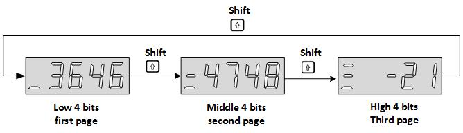
| U0-12 | Monitoring name | Range | Category | Panel display | Unit | Data type |
| Real-time torque value | -3000 to 3000 | Universal | Decimal | 0.1% | 16-bit |
| U0-13 | Monitoring name | Range | Category | Panel display | Unit | Data type |
Encoder cumulative position (Lower 32 bits) | -231 to 231 | Universal | Decimal | Encoder unit | 32-bit |
| U0-15 | Monitoring name | Range | Category | Panel display | Unit | Data type |
Encoder cumulative position (High 32 bits) | -231 to 231 | Universal | Decimal | Encoder unit | 32-bit | |
| Display the cumulative data of encoder position. It is used with U0-13 cooperatively. | ||||||
| U0-16 | Monitoring name | Range | Category | Panel display | Unit | Data type |
| Shutdown vibration frequency | 0 to 2000 | Universal | Decimal | 0.1Hz | 16-bit | |
| Display the detected frequency during the deceleration to stop. | ||||||
| U0-17 | Monitoring name | Range | Category | Panel display | Unit | Data type |
| DI input signal status | 00000000 to 11111111 | Universal | Binary | Encoder unit | 16-bit | |
Display the current level status of DI terminal. The upper part of the digital tube of servo drive panel is lit up to indicate a high level (denoted by "1"). The lower part is lit up to indicate a low level (denoted by "0"). Take the DI1 to DI7 terminals as the high level and DI8 as the low level as an example. The corresponding binary code is "01111111", and Wecon servo control device debugging software U0-17 displays the current binary value is 0b0111 1111. The panel of servo drive is displayed as below.
| ||||||

| U0-19 | Monitoring name | Range | Category | Panel display | Unit | Data type |
| DO output signal status | 00000000 to 00001111 | Universal | Binary | Encoder unit | 16-bit | |
Display the current level status of 4 DO terminals. The upper part of the digital tube of servo drive panel is lit up to indicate a high level (denoted by "1"). The lower part is lit up to indicate a low level (denoted by "0"). Take the DO1, DO2 and DO3 terminals as the high level and DO2 as the low level as an example. The corresponding binary code is "1101", and Wecon servo upper computer debugging software U0-17 displays the current binary value is 0b0000 1101. The panel of servo drive is displayed as below.
| ||||||

| U0-20 | Monitoring name | Range | Category | Panel display | Unit | Data type |
| Real-time load inertia ratio | 0 to 1000000 | Universal | Decimal | % | 16-bit | |
Display the current load inertia ratio. If the load inertia ratio is 3 times (300%) , the panel of servo drive is displayed as below.
| ||||||

| U0-21 | Monitoring name | Range | Category | Panel display | Unit | Data type | ||||
| AI1 input voltage value | - | Universal | Decimal | V | 16-bit | |||||
| Reserved☆ | ||||||||||
Display the actual sampling voltage of analog channel 1.
“☆” indicates that the VD2F servo drive does not have this monitoring. | ||||||||||


| U0-22 | Monitoring name | Range | Category | Panel display | Unit | Data type |
| AI2 input voltage value | - | Universal | Decimal | V | 16-bit | |
| Reserved☆ | ||||||
| “☆” indicates that the VD2F servo drive does not have this monitoring. | ||||||
| U0-23 | Monitoring name | Range | Category | Panel display | Unit | Data type |
| Vibration Frequency | - | Universal | Decimal | Hz | 16-bit |
| U0-24 | Monitoring name | Range | Category | Panel display | Unit | Data type |
| Vibration amplitude | - | Universal | Decimal | rpm | 16-bit |
| U0-25 | Monitoring name | Range | Category | Panel display | Unit | Data type |
| Forward torque limit value | 0 to 300 | Universal | Decimal | % | 16-bit | |
Display the set value of P01-15 (forward torque limit) of servo drive. If U0-25 is 288%, the panel of servo drive is displayed as below.
| ||||||

| U0-26 | Monitoring name | Range | Category | Panel display | Unit | Data type |
| Reverse torque limit value | -300 to 0 | Universal | Decimal | % | 16-bit | |
Display the set value of P01-16 (reverse torque limit) of servo drive. If U0-26 is 300%, the panel of servo drive is displayed as below.
| ||||||

| U0-27 | Monitoring name | Range | Category | Panel display | Unit | Data type |
| Forward speed limit value | 0 to 5000 | Universal | Decimal | rpm | 16-bit | |
Display the set value of P01-12 (forward speed threshold) of servo drive. If P01-12 is set to 2000, the panel of servo drive is displayed as below.
| ||||||

| U0-28 | Monitoring name | Range | Category | Panel display | Unit | Data type |
| Reverse speed limit value | -5000 to 0 | Universal | Decimal | rpm | 16-bit | |
Display the set value of P01-13 (reverse speed threshold) of servo drive. If P01-13 is set to 3000, the panel of servo drive is displayed as below.
| ||||||

| U0-29 | Monitoring name | Range | Category | Panel display | Unit | Data type |
| Mechanical angle | 0 to 359 | Universal | Decimal | ° | 16-bit | |
Display current mechanical angle of motor. 0 corresponds to a mechanical angle of 0 degree. If the mechanical angle is 270°, the panel of servo drive is displayed as below.
| ||||||

| U0-30 | Monitoring name | Range | Category | Panel display | Unit | Data type |
| Electrical angle | 0 to 359 | Universal | Decimal | ° | 16-bit | |
Display current electrical angle of motor. The accuracy is 1°. When the motor rotates, the angle range is 360°. When the motor is 4 poles, every time the motor is rotated one turn, it undergoes a change process of 0° to 359° four times.
| ||||||

| U0-31 | Monitoring name | Range | Category | Panel display | Unit | Data type |
| Bus voltage | - | Universal | Decimal | V | 16-bit | |
Display the DC bus voltage of the main circuit input voltage of servo drive after rectification. If the bus voltage is 310.9, the panel of servo drive is displayed as below.
| ||||||

| U0-32 | Monitoring name | Range | Category | Panel display | Unit | Data type |
| Radiator temperature | - | Universal | Decimal | °C | 16-bit |
| U0-33 | Monitoring name | Range | Category | Panel display | Unit | Data type |
| Instantaneous output power | - | Universal | Decimal | W | 16-bit |
| U0-34 | Monitoring name | Range | Category | Panel display | Unit | Data type |
| Average output power | - | Universal | Decimal | W | 16-bit |
| U0-35 | Monitoring name | Range | Category | Panel display | Unit | Data type |
| Total operation time (hour) | - | Universal | Decimal | h | 16-bit |
| U0-37 | Monitoring name | Range | Category | Panel display | Unit | Data type |
| Total operation time (minutes) | - | Universal | Decimal | min | 16-bit |
| U0-38 | Monitoring name | Range | Category | Panel display | Unit | Data type |
| Total operation time (seconds) | - | Universal | Decimal | s | 16-bit |
| U0-39 | Monitoring name | Range | Category | Panel display | Unit | Data type |
| Load torque percentage | - | Universal | Decimal | % | 16-bit | |
Display current load torque percentage. If the current load torque percentage is 10.3%, the panel of servo drive is displayed as below.
| ||||||

| U0-40 | Monitoring name | Range | Category | Panel display | Unit | Data type |
| Current operation time (hour) | - | Universal | Decimal | h | 16-bit |
| U0-42 | Monitoring name | Range | Category | Panel display | Unit | Data type |
| Current operation time (minutes) | - | Universal | Decimal | min | 16-bit |
| U0-43 | Monitoring name | Range | Category | Panel display | Unit | Data type |
| Current operation time (seconds) | - | Universal | Decimal | s | 16-bit |
| U0-44 | Monitoring name | Range | Category | Panel display | Unit | Data type |
| Instantaneous braking resistor power | - | Universal | Decimal | W | 16-bit |
| U0-46 | Monitoring name | Range | Category | Panel display | Unit | Data type |
| Average braking resistor power | - | Universal | Decimal | W | 16-bit |
| U0-48 | Monitoring name | Range | Category | Panel display | Unit | Data type |
| Power-on times | - | Universal | Decimal | Times | 16-bit |
| U0-49 | Monitoring value name | Range | Category | Panel display | Unit | Data type |
| Internal counting of motor overload | -- | Universal | Decimal | 100 | 16 Bit |
| U0-50 | Monitoring name | Range | Category | Panel display | Unit | Data type |
| Motor cumulative number of turns (low 32 bits) | 0 to 232-1 | Universal | Decimal | Cycles | 32-bit |
| U0-51 | Monitoring name | Range | Category | Panel display | Unit | Data type |
| Motor cumulative number of turns (high 32 bits) | 0 to 232-1 | Universal | Decimal | Cycles | 32-bit |
| U0-53 | Monitoring name | Range | Category | Panel display | Unit | Data type |
| Motor model code | - | Universal | Hexadecimal | - | 16-bit | |
Display current Motor model code. Take WD80M-07530S-A1F (A026) as an example, the panel of servo drive is displayed as below.
| ||||||

| U0-54 | Monitoring name | Range | Category | Panel display | Unit | Data type |
| Absolute encoder position within 1 circle | 0 to 232-1 | Universal | Decimal | Encoder unit | 32-bit | |
| Display the single turn position feedback value of absolute encoder | ||||||
| U0-55 | Monitoring name | Range | Category | Panel display | Unit | Data type |
Circle numbers of multi-turn absolute encoder | 0 to 65535 | Universal | Decimal | Encoder unit | 16-bit | |
| Display the circle number of multi-turn absolute encoder | ||||||
| U0-56 | Monitoring name | Range | Category | Panel display | Unit | Data type |
| Multi-turn absolute encoder current position | -231 to 231 | Universal | Decimal | Instruction unit | 32-bit | |
| Display the absolute position of motor (instruction unit). It is only valid is multi-turn absolute encoder motor | ||||||
| U0-59 | Monitoring name | Range | Category | Panel display | Unit | Data type |
| Historical maximum bus voltage | 0 to 65535 | Universal | Decimal | V | 16-bit | |
| Display the bus voltage history maximum. | ||||||
| U0-60 | Monitoring name | Range | Category | Panel display | Unit | Data type |
| Historical maximum average power | 0 to 65535 | Universal | Decimal | W | 16-bit | |
| Display average power history max. | ||||||
Group U1 Warning monitoring
| U1-01 | Monitoring name | Range | Category | Panel display | Unit | Data type | ||||
| Current fault code | - | Warning | - | - | 16-bit | |||||
If there is fault in servo drive, it would display the corresponding fault. If not, the panel displays “---”. Take the fault “encoder disconnect” as an example, the panel of servo drive is displayed as below.
| ||||||||||


| U1-02 | Monitoring name | Range | Category | Panel display | Unit | Data type | ||||
| Current warning code | - | Warning | - | - | 16-bit | |||||
If there is warning in servo drive, it would display the corresponding warning. If not, the panel displays “---”. Take the warning “DI port configuration duplication” as an example, the panel is displayed as below.
| ||||||||||

| U1-03 | Monitoring name | Range | Category | Panel display | Unit | Data type |
| U phase current when faults occur | - | Warning | Decimal | A | 16-bit |
| U1-04 | Monitoring name | Range | Category | Panel display | Unit | Data type |
| V phase current when faults occur | - | Warning | Decimal | A | 16-bit |
| U1-05 | Monitoring name | Range | Category | Panel display | Unit | Data type |
| Bus voltage when faults occur | - | Warning | Decimal | V | 16-bit |
| U1-06 | Monitoring name | Range | Category | Panel display | Unit | Data type |
| IGBT temperature when faults occur | - | Warning | Decimal | ℃ | 16-bit |
| U1-07 | Monitoring name | Range | Category | Panel display | Unit | Data type |
| Torque component when faults occur | - | Warning | Decimal | % | 16-bit |
| U1-08 | Monitoring name | Range | Category | Panel display | Unit | Data type |
| Excitation component when faults occur | - | Warning | Decimal | % | 16-bit |
| U1-09 | Monitoring name | Range | Category | Panel display | Unit | Data type |
| Position deviation when faults occur | - | Warning | Decimal | Encoder unit | 32-bit |
| U1-10 | Monitoring name | Range | Category | Panel display | Unit | Data type |
| The speed when faults occur | - | Warning | Decimal | rpm | 16-bit |
| U1-11 | Monitoring name | Range | Category | Panel display | Unit | Data type |
| The time when faults occur | - | Warning | Decimal | s | 16-bit |
| U1-12 | Monitoring name | Range | Category | Panel display | Unit | Data type |
| Number of faults in this operation | - | Warning | Decimal | - | 16-bit |
| U1-13 | Monitoring name | Range | Category | Panel display | Unit | Data type |
| Number of warnings in this operation | - | Warning | Decimal | - | 16-bit |
| U1-14 | Monitoring name | Range | Category | Panel display | Unit | Data type |
| Total number of historical faults | - | Warning | Decimal | - | 16-bit |
| U1-15 | Monitoring name | Range | Category | Panel display | Unit | Data type |
| Total number of historical warnings | - | Warning | Decimal | - | 16-bit |
| U1-16 | Monitoring name | Range | Category | Panel display | Unit | Data type |
| The 1st fault code of the most recent | - | Warning | - | - | 16-bit | |
| Display the 1st fault code of the most recent of servo drive | ||||||
| U1-17 | Monitoring name | Range | Category | Panel display | Unit | Data type |
| The 2nd fault code of the most recent | - | Warning | - | - | 16-bit |
| U1-18 | Monitoring name | Range | Category | Panel display | Unit | Data type |
| The 3rd fault code of the most recent | - | Warning | - | - | 16-bit |
| U1-19 | Monitoring name | Range | Category | Panel display | Unit | Data type |
| The 4th fault code of the most recent | - | Warning | - | - | 16-bit |
| U1-20 | Monitoring name | Range | Category | Panel display | Unit | Data type |
| The 5th fault code of the most recent | - | Warning | - | - | 16-bit |
| U1-21 | Monitoring name | Range | Category | Panel display | Unit | Data type |
| The 1st warning code of the most recent | - | Warning | - | - | 16-bit | |
| Display the 1st warning code of the most recent of servo drive | ||||||
| U1-22 | Monitoring name | Range | Category | Panel display | Unit | Data type |
| The 2nd warning code of the most recent | - | Warning | - | - | 16-bit |
| U1-23 | Monitoring name | Range | Category | Panel display | Unit | Data type |
| The 3rd warning code of the most recent | - | Warning | - | - | 16-bit |
| U1-24 | Monitoring name | Range | Category | Panel display | Unit | Data type |
| The 4th warning code of the most recent | - | Warning | - | - | 16-bit |
| U1-25 | Monitoring name | Range | Category | Panel display | Unit | Data type |
| The 5th warning code of the most recent | - | Warning | - | - | 16-bit |
Group U2 Device monitoring
| U2-01 | Monitoring name | Range | Category | Panel display | Unit | Data type |
| Product series | - | Device | Hexadecimal | - | 16-bit | |
Display the product series code of servo drive. The VD2R servo driver code is 0x4432, and the VD2F servo driver code is 0x4432
| ||||||


| U2-02 | Monitoring name | Range | Category | Panel display | Unit | Data type |
| Model | - | Device | Hexadecimal | - | 16-bit | |
Display the servo drive model.
| ||||||


| U2-03 | Monitoring name | Range | Category | Panel display | Unit | Data type | ||||||||||||||||||||||||||||||||||||||||||||||||||||||||||||||||||||||||||||||||||||||||||||||||||||||||
| Model | - | Warning | Hexadecimal | - | 16-bit | |||||||||||||||||||||||||||||||||||||||||||||||||||||||||||||||||||||||||||||||||||||||||||||||||||||||||
| ||||||||||||||||||||||||||||||||||||||||||||||||||||||||||||||||||||||||||||||||||||||||||||||||||||||||||||||


| U2-04 | Monitoring name | Range | Category | Panel display | Unit | Data type |
| Firmware version | - | Device | Decimal | - | 16-bit | |
Display the firmware version Display format: X.YY. For example, 1.13. The panel is displayed as below.
| ||||||

| U2-05 | Monitoring name | Range | Category | Panel display | Unit | Data type |
| FPGA version | - | Device | Decimal | - | 16-bit | |
Display the hardware version (FPGA) Display format: X.YY. For example, 1.01. The panel is displayed as below.
| ||||||

| U2-06 | Monitoring name | Range | Category | Panel display | Unit | Data type |
| Manufacture date (year) | - | Device | Decimal | Year | 16-bit | |
| Firmware date (year) * | ||||||
| Display the year of manufacture of the VD2F drive firmware. | ||||||
| U2-07 | Monitoring name | Range | Category | Panel display | Unit | Data type |
| Manufacture date (month) | - | Device | Decimal | Month | 16-bit | |
| Firmware date (month) * | ||||||
| Display the month of manufacture of the VD2F drive firmware. | ||||||
| U2-08 | Monitoring name | Range | Category | Panel display | Unit | Data type | ||||||
| - | Device | Decimal | Day | 16-bit | ||||||||
| Firmware date (day) * | ||||||||||||
Displays the production date of the VD2F drive firmware. For example, the firmware production day of VD2F-014SA1P_V1.01 is January 10, 2022, the panel is displayed as below.
| ||||||||||||


| U2-09 | Monitoring name | Range | Category | Panel display | Unit | Data type |
| Device serial number 1 | - | Warning | Decimal | - | 16-bit |
| U2-10 | Monitoring name | Range | Category | Panel display | Unit | Data type |
| Device serial number 2 | - | Warning | Decimal | - | 16-bit |
| U2-11 | Monitoring name | Range | Category | Panel display | Unit | Data type |
| Device serial number 3 | - | Warning | Decimal | - | 16-bit |
| U2-12 | Monitoring name | Range | Category | Panel display | Unit | Data type |
| Device serial number 4 | - | Warning | Decimal | - | 16-bit |
| U2-13 | Monitoring name | Range | Category | Panel display | Unit | Data type |
| Device serial number 5 | - | Warning | Decimal | - | 16-bit |
| U2-14 | Monitoring name | Range | Category | Panel display | Unit | Data type |
| Device serial number 6 | - | Warning | Decimal | - | 16-bit |
| U2-15 | Monitoring name | Range | Category | Panel display | Unit | Data type |
| Device serial number 7 | - | Warning | Decimal | - | 16-bit |
| U2-16 | Monitoring name | Range | Category | Panel display | Unit | Data type |
| Device serial number 8 | - | Warning | Decimal | - | 16-bit |