FX3U,3G,3GA Serial
Supported Series: Mitsubishi FX3U, FX3G, FX3GA series
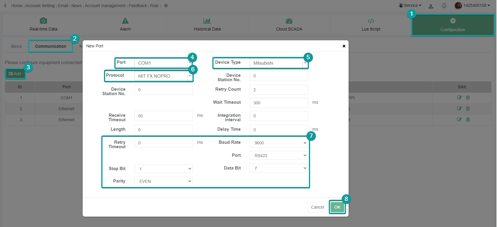
V-BOX Settings
| Item | Settings | Note |
| Protocol | Mitsubishi FX3U/3G/3GA | |
| Connection | RS422/RS485/RS232 | |
| Baud rate | 9600~115200 | |
| Data bit | 7/8 | |
| Parity | EVEN/Odd/None | |
| Stop bit | 1/2 | |
| PLC station No. | 1~255 |

Address List
| Type | Device registers | Format | Range | Note |
| Bit | X | X o | 0~303237 | |
| Y | Y o | 0~303237 | ||
| M | M d | 0~99999 | ||
| T | T d | 0~99999 | ||
| C | C d | 0~99999 | ||
| S | S d | 0~99999 | ||
| SM | SM d | 8000~9999 | ||
| Word | X | X o | 0~303237 | |
| Y | Y o | 0~303237 | ||
| M | M d | 0~99999 | ||
| T | T d | 0~99999 | ||
| C | C d | 0~199 | ||
| D | D d | 0~7999 | ||
| S | S d | 0~99999 | ||
| SD | SD d | 8000~9999 |
PLC Setting
Open GX Works2, create a new PLC project or open the project that has been created.
Create new project: [Project]→[New]→[Series] FXCPU→[Type] FX3G/FX3GC→[OK].


PLC Default Parameters:
[Connection type]RS422;[Baud rate]9600, [Data bit]7, [Stop bit]1,[Parity]EVEN; [Station number]0
Note:The serial port parameters should be set depending on field requirements
PC and PLC connection:
[All connection]→[Connection 1]→[Transfer Setup Connection1]→[Serial USB]→RS-232C: PC and PLC are connected by USB to RS232 adapter,choose corresponding [COM Port]COM 5 →[Transmission speed]9.6Kbps→[setup] →[Parity]EVEN→[Data bits]7→[Stop bits]1→[OK]

Connection test:when connection is OK,the GX Works2 prompts “Successfully connected with the FX3G/FX3GCCPU.”

[PLC]→[Write to PLC]→[Online operation]→[Param+program]→[Execute]→[OK]

Cable Wiring
RS422


FX NOPROTOCOL
Mitsubishi FX3G-RS232-BD
V-Box Settings
| Item | Settings | Note |
|---|---|---|
| Protocol | Mitsubishi FX NOPROTOCOL | |
| Connection | RS232 | |
| Baud rate | 9600 | |
| Data bit | 7 | |
| Parity | EVEN | |
| Stop bit | 1 | |
| PLC station No. | 0 |
Address List
| Type | Device registers | Format | Range | Note |
|---|---|---|---|---|
| Bit | X | X o | 0~303237 | |
| Y | Y o | 0~303237 | ||
| M | M d | 0~99999 | ||
| T | T d | 0~99999 | ||
| C | C d | 0~99999 | ||
| S | S d | 0~99999 | ||
| SM | SM d | 8000~9999 | ||
| Lamp | Lamp d | 0~0 | ||
| Word | X | X o | 0~303237 | |
| Y | Y o | 0~303237 | ||
| M | M d | 0~99999 | ||
| T | T d | 0~99999 | ||
| C | C d | 0~199 | ||
| D | D d | 0~7999 | ||
| S | S d | 0~99999 | ||
| SD | SD d | 8000~9999 |
Cable Wiring

FX3U Ethernet
Supported Modules: FX3U-ENET-ADP, FX3U-ENET-L
V-BOX Settings
| Items | Settings | Note |
| Protocol | Mitsubishi FX3U | |
| Connection | Ethernet | |
| Port No. | 5009 | Must be the same as the PLC setting |
| PLC station No. | 0 |

Address List
| Type | Device registers | Format | Range | Note |
| Bit | X | X OOO | 0~377 | |
| Y | Y OOO | 0~377 | ||
| M | M DDDD | 0~7679 | ||
| SM | SM DDDD | 8000~8511 | ||
| S | S DDDD | 0~4095 | ||
| TS | TS DDD | 0~511 | ||
| CS | CS DDD | 0~255 | ||
| Word | CN | CN DDD | 0~199 | |
| TN | TN DDD | 0~511 | ||
| D | D DDDD | 0~7999 | ||
| SD | SD DDDD | 8000~8511 | ||
| R | R DDDDD | 0~32767 |
Ethernet Module Settings
FX3U-ENET-L module configuration
Set up the FX3U-ENET-L Ethernet module settings as follows.
Select the module location, which in this document is Module 0.

Select "Operational setting" to enter the following screen.
The Ethernet module IP is set to 192.168.39.254 in this document, and other options are default.

Select "Open setting" to enter the setting interface, the settings are as follows.
The third item "Protocol" selects TCP, and "Open system" selects MELSOFT connection, which allows the
Mitsubishi programming software GX works2 to communicate with the FX3U via the Ethernet module.

Click on "transter setup" - "PC side I/F setting", see the following figure.
After setting, the first download must use the programming cable, as shown in the figure; after that, can
use the IP set in the "Ethernet board" to communicate directly with the network cable.


read and write data from the Ethernet module

Set "Transter setup" to COM communication, and read or write operation as shown below

PLC Settings (GX Works 2)
Create a blank FX5U project
Find Current Connection in the navigation

Select Connection Channel List
Select Ethernet board communication

Select Ethernet Module
Set the IP address of the PLC

Read or write PLC data, in this document is read


FX5U Serial
Mitsubishi FX5U series PLC
V-BOX Settings
| Item | Settings | Note |
| Protocol | Mitsubishi FX5U | |
| Connection | RS422/RS485 | |
| Baud rate | 9600 | |
| Data bit | 7 | |
| Parity | Odd | |
| Stop bit | 1 | |
| PLC station No. | 1~255 | Need to be the same as PLC settings |

Address List
| Type | Device registers | Format | Range | Note |
| Bit | X | X o | 0~303237 | |
| Y | Y o | 0~303237 | ||
| M | M d | 0~99999 | ||
| B | B h | 0~7FFF | ||
| F | F d | 0~32767 | ||
| SB | SB h | 0~7FFF | ||
| TS | TS d | 0~1023 | ||
| TC | TC d | 0~1023 | ||
| STS | STS d | 0~1023 | ||
| STC | STS d | 0~1023 | ||
| CS | CS d | 0~1023 | ||
| CC | CC d | 0~1023 | ||
| SM | SM d | 0~9999 | ||
| L | L d | 0~32767 | ||
| S | S d | 0~4095 | ||
| Word | W | W h | 0~3FF | |
| TN | TN d | 0~1023 | ||
| STN | STN d | 0~1023 | ||
| CN | CN d | 0~1023 | ||
| R | R d | 0~32767 | ||
| SW | SW h | 0~7FFF | ||
| Z | Z d | 0~23 | ||
| D | D d | 0~7999 | ||
| SD | SD d | 0~11999 |
PLC Settings
Create a blank FX5U project
Open GX Works3, create a new PLC project or open the project that has been created. Create new project: [Project]→[New]→[Series] FX5CPU→[Type] FX5U→[OK].


PLC Default Parameters:
[Navigation]→[Parameter]→[FX5UCPU]→[Module Parameter]→[485 Serial Port]:[Basic Settings] →[ Communication Protocol Type] MC Protocol→[Advanced Settings]:[Baud rate]9600Kbps, [Data Length]7, [Stop bit]1,[Parity]Odd.

[Navigation]→[Parameter]→[FX5UCPU]→[Module Parameter]→[485 Serial Port]: [fixed Setting] →[Station No.]0→[Message Pattern] Pattern 1 (X,Y OCT)→[Apply]

Cable Wiring
RS422


FX5U Ethernet
Mitsubishi FX5U series PLC
V-BOX Settings
| Items | Settings | Note |
| Protocol | Mitsubishi FX5U | |
| Connection | Ethernet | |
| Port No. | 5002 | Must be the same as the PLC setting |
| PLC station No. | 0 |

Address List
| Type | Device registers | Format | Range | Note |
| Bit | X | X o | 0~303237 | |
| Y | Y o | 0~303237 | ||
| M | M d | 0~99999 | ||
| B | B h | 0~7FFF | ||
| F | F d | 0~32767 | ||
| SB | SB h | 0~7FFF | ||
| TS | TS d | 0~1023 | ||
| TC | TC d | 0~1023 | ||
| STS | STS d | 0~1023 | ||
| STC | STS d | 0~1023 | ||
| CS | CS d | 0~1023 | ||
| CC | CC d | 0~1023 | ||
| SM | SM d | 0~9999 | ||
| L | L d | 0~32767 | ||
| S | S d | 0~4095 | ||
| Word | W | W h | 0~3FF | |
| TN | TN d | 0~1023 | ||
| STN | STN d | 0~1023 | ||
| CN | CN d | 0~1023 | ||
| R | R d | 0~32767 | ||
| SW | SW h | 0~7FFF | ||
| Z | Z d | 0~23 | ||
| D | D d | 0~7999 | ||
| SD | SD d | 0~11999 |
PLC Settings
Open GX Works3, create a new PLC project or open the project that has been created.
Create new project: [Project]→[New]→[Series] FX5CPU→[Type] FX5U→[OK].
PLC Default Parameters:
[Navigation]→[Parameter]→[FX5UCPU]→[Module Parameter]→[Ethernet Port]:[Basic Settings] →[Own node settings]:[IP Address]192.168.40.11, [Subnet Mask]255.255.255.0, [Default Gateway]192.168.40.1,[ Communication Data Code] Binary.

[External Device Configuration]→[Detailed Settings]→[Ethernet Configuration(Built-in Ethernet Port)]→[Ethernet Device (General)]→[SLMP Connection Module] Drag under Host for Connection No.1→[Port No.]5002→[Close with Reflecting the Setting]

PC and PLC connection
[Online]→[Current Connection Destination]→[Direct Coupled Setting]→[Ethernet]→[Adapter] Realtek PCIe GBE Family Controller→[Communication Test]: Successfully connected with the FX5UCPU.

Downloading PLC project
[Online]→[Write to PLC]→[Online Data operation]→[Param+program]→[Execute]→[Yes] →[Yes to all]

Cable Wiring

L02 Serial
Mitsubishi L02 series CPU built-in serial port.
V-BOX Settings
| Item | Settings | Note |
| Protocol | Mitsubishi L02 | |
| Connection | RS422 | |
| Baud rate | 115200 | |
| Data bit | 8 | |
| Parity | Odd | |
| Stop bit | 1 | |
| PLC station No. | 1~255 | Need to be the same as PLC settings |

Address List
| Type | Device registers | Format | Range | Note |
| Bit | X | X h | 0~FFFF | |
| Y | Y h | 0~FFFF | ||
| M | M d | 0~9999 | ||
| L | L d | 0~9999 | ||
| F | F d | 0~9999 | ||
| B | B h | 0~FFFF | ||
| V | V d | 0~2047 | ||
| TC | TC d | 0~9999 | ||
| SS | SS d | 0~9999 | ||
| SC | SC d | 0~9999 | ||
| CS | CS d | 0~9999 | ||
| CC | CC d | 0~9999 | ||
| SB | SB h | 0~FFFF | ||
| SM | SM d | 0~2047 | ||
| STS | STS d | 0~1023 | ||
| S | S d | 0~9999 | ||
| DX | DX h | 0~FFFF | ||
| DY | DY h | 0~FFFF | ||
| TS | TS d | 0~9999 | ||
| Dbit | Dbit d.d | 0~99999.0~15 | ||
| Word | W | W h | 0~FFFF | |
| TN | TN d | 0~99999 | ||
| SN | SN d | 0~99999 | ||
| CN | CN d | 0~99999 | ||
| R | R d | 0~99999 | ||
| SW | SW h | 0~FFFF | ||
| Z | Z d | 0~99999 | ||
| ZR | ZR h | 0~FFFF | ||
| D | D d | 0~99999 |
Cable Wiring
RS422


L02 Ethernet
Mitsubishi L series CPU built-in Ethernet port.
V-BOX Settings
| Items | Settings | Note |
| Protocol | MIT L02 CPU MELSEC | |
| Connection | Ethernet | |
| Port No. | 1025 | Must be the same as the PLC setting |
| PLC station No. | 0 | Must be the same as the PLC setting |

PLC Settings (GX Works2 )
Create a project
Set PLC IP, subnet mask and gateway;
Select [Binary Code] as communication data code;

Set PLC port number, for example 1025

Save settings;
Download project into PLC device;
Restart PLC device;
Cable Wiring
Q12H Serial
This Demo shows V-BOX communicate with Q12H PLC by Q02H serial Protocol
QJ71E71 Ethernet
Mitsubishi QJ71E71 Ethernet communication module;
V-BOX Settings
| Items | Settings | Note |
| Protocol | MIT QJ71E71 MELSEC | |
| Connection | Ethernet | |
| Port No. | 1025 | Must be the same as the PLC setting |
| PLC station No. | 0 | Must be the same as the PLC setting |

Address List
| Type | Device registers | Format | Range | Note |
| Bit | X | X h | 0~1FFF | |
| Y | Y h | 0~1FFF | ||
| M | M d | 0~99999 | ||
| L | L d | 0~8191 | ||
| F | F d | 0~2047 | ||
| B | B h | 0~1FFF | ||
| V | V d | 0~2047 | ||
| TS | TS d | 0~2047 | ||
| TC | TC d | 0~2047 | ||
| SS | SS d | 0~2047 | ||
| SC | SC d | 0~2047 | ||
| CS | CS d | 0~1023 | ||
| CC | CC d | 0~1023 | ||
| SB | SB h | 0~7FF | ||
| S | S d | 0~8191 | ||
| DX | DX h | 0~1FFF | ||
| DY | DY h | 0~1FFF | ||
| SM | SM d | 8000~9999 | ||
| Word | SD | SD d | 0~2047 | |
| D | D d | 0~12287 | ||
| W | W h | 0~1FFF | ||
| TN | TN d | 0~2047 | ||
| SN | SN d | 0~2047 | ||
| CN | CN d | 0~1023 | ||
| R | R d | 0~32767 | ||
| SW | SW h | 0~7FF | ||
| Z | Z d | 0~15 | ||
| ZR | ZR h | 0~FE7FF |
PLC Settings(GX Works2)
- Click [Ethernet/CC IE/MELSECNET];
- Please select [Ethernet] as network type;
- Set station I/O number according to situation (For example, 0020 means that the module is connected to PLC CPU in first order);
- Select [Online] as Mode;

- Click [Operation setting] to set IP;
- Select [Binary Code] as [Communication Data Code];

- Click [Open setting]
- Set protocol: TCP;
- Set [unpassive] in [Open system];
- Set [receive] in [Fixed buffer];
- Set [procedure Exist] in [Fixed buffer communication];
- Disable [Pairing open];
- Set [No confirm] in [Existence confirmation];
- Host station port number: 5009;
- Save settings;

- Download project into PLC and restart it
Cable Wiring
Q03UDV
Mitsubishi Q03UDV
V-BOX Settings
| Items | Settings | Note |
| Protocol | MIT L02 CPU MELSEC PROTOCOL | |
| Connection | Ethernet | |
| Port No. | 1025 | Must be the same as the PLC setting |
| PLC station No. | 0 | Must be the same as the PLC setting |

Address List
| Type | Device registers | Format | Range | Note |
| Bit | X | X h | 0~1fff | |
| Y | Y h | 0~1fff | ||
| SM | SM d | 0~2047 | ||
| M | M d | 0~99999 | ||
| L | L d | 0~8191 | ||
| F | F d | 0~2047 | ||
| V | V d | 0~2047 | ||
| B | B h | 0~1fff | ||
| TS | TS d | 0~2047 | ||
| TC | TC d | 0~2047 | ||
| SS | SS d | 0~2047 | ||
| SC | SC d | 0~2047 | ||
| CS | CS d | 0~1023 | ||
| CC | CC d | 0~1023 | ||
| SB | SB h | 0~7ff | ||
| S | S d | 0~8191 | ||
| DX | DX h | 0~1fff | ||
| DY | DY h | 0~1fff | ||
| Word | SD | SD d | 0~2047 | |
| D | D d | 0~12287 | ||
| W | W h | 0~1fff | ||
| TN | TN d | 0~2047 | ||
| SN | SN d | 0~2047 | ||
| CN | CN d | 0~1023 | ||
| SW | SW h | 0~7ff | ||
| Z | Z d | 0~15 | ||
| R | R d | 0~32767 | ||
| ZR | ZR h | 0~fe7ff |
PLC Settings(GX Works2)
PC and PLC connection:
- Online→Read from PLC

- choose PLC Series→OK

- serial USB→OK

- Choose Parameter、Global Device Comment and Device Memory→Execute

- OK→wait loading successfully→Close

- Navigation→Parameter→PLC Parameter→IP Address Setting→Built-in Ethernet Port Setting→Host Station(Same as the port on V-box)→End

- Debug→Start/ Stop Simulation→wait loading successfully→Close


Cable Wiring