About brake resistors and brake units?
1.Introduction of brake unit and brake resistor
- The braking unit is a module with the braking resistor connected to it.
- A braking unit without a connected braking resistor lacks braking capability and cannot dissipate energy.
- The braking unit can be understood as a switch device that detects voltage fluctuations.
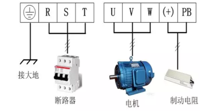
Built-in brake unit
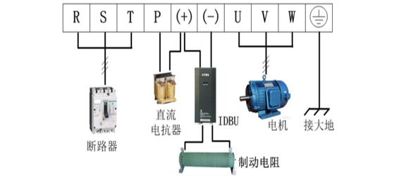
External brake unit
2.Principles for selecting braking resistors
If an incompatible braking resistor is used:
- Reduced braking effectiveness: The braking resistor cannot effectively dissipate the electrical energy generated by the inverter, resulting in poor braking performance and extended braking time.
- Inverter overload: When the resistance value of the braking resistor is too high, the inverter cannot effectively dissipate energy during braking, which may trigger the inverter's internal overload protection mechanism and potentially damage the inverter.
- System instability: Excessively high resistance values may cause voltage fluctuations on the grid side, affecting the stability of the entire system and potentially causing malfunctions in other equipment.
VB brake resistance selection table
3.Parameter Settings for different models
Regarding the use of braking resistors with VB:
FA.03 Overvoltage stall gain: Used to actively increase the output frequency or current when the voltage approaches the overvoltage protection threshold, consume the pump's voltage energy, suppress the voltage rise rate, extend the deceleration time, and avoid triggering a shutdown.
When VB uses a braking resistor, to avoid the overvoltage stall function causing extended deceleration time, set FA.03=0 to disable the overvoltage stall function.
FA.04 corresponds to the bus voltage protection threshold.
We recommend FA.04=120% for VB 0-22 kW and FA.04=150% for VB over 22 kW.
When VB uses an internal braking unit, the braking function needs to be activated earlier. When VB uses an external braking unit, FA.04 needs to be increased to delay the activation of the VB braking function, prioritizing the operation of the external braking unit.
F4.16=0 disables the AVR. When using a braking resistor, if the AVR function is not disabled, the inverter will first perform its own braking adjustment, thereby extending the braking time. After the AVR function is disabled, the braking unit and braking resistor will take priority in braking.
Regarding the use of braking resistors with VC: It has a built-in braking resistor detection algorithm, so you only need to set FA.03=1110.
VNZ200 P9.03=0
VT200 P3.23=0