How to solve Err06: Overvoltage during deceleration?
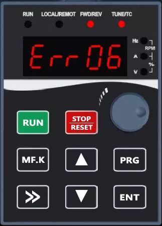
Panel display
Common causes of failure
The inverter detects that the bus voltage is too high during deceleration will display deceleration overvoltage. There are two main reasons for the voltage increase: power overvoltage and regenerative overvoltage. The input power supply of the frequency converter is generally allowed to be 437V, and the general power overvoltage is less, while the common one is the regenerative overvoltage caused by the too short deceleration time setting of the inverter, the sudden dumping of the load in the deceleration of the motor, and the too large inertia of the load dragging on the motor end.
Solution
1. Power overvoltage
- Measurement of inverter input R/S/T phase-to-phase voltage, if the phase-to-phase voltage is not stable and too high can be measured in the inverter input power plus voltage regulator.
- If the input voltage is stable and too high, you can adjust the transformer's voltage gear general transformer has three gears low, medium and high (requires professional electrician to modify the gear operation)
2.Regenerative overvoltage
- Reason: when the large inertia (flywheel torque) load deceleration inverter deceleration time is set too short; motor is affected by external force (fan, drafting machine) or bit energy load (elevator, crane) devolution. So that the actual motor speed is higher than the command speed of the inverter, that is to say, the motor rotor speed exceeds the synchronous speed, then the motor's turnover rate is negative, the rotor winding cuts the direction of the rotating magnetic field in the opposite direction to the motor state, and the electromagnetic torque it generates is the braking torque that hinders the direction of rotation. Therefore, the motor is actually in the state of power generation, and the kinetic energy of the load is "regenerated" into electrical energy.
- If there is no special requirement for stopping time or position, you can extend the deceleration time of inverter (F0.19) or change it to free stopping (F1.10 to 1).
- If there are requirements for stopping time or position, DC braking can be turned on.
| unction Code | Parameter Name | Setting Range | Default | Property | Add. HEX |
|---|---|---|---|---|---|
| F1.11 | Trigging frequency of DC braking at stop | 0.00Hz ~F0.10 | 0.00Hz | ○ | 010B |
| F1.12 | Waiting time of DC braking at stop | 0.0s ~ 100.0s | 0.0s | ○ | 010C |
| F1.13 | The current of DC braking at stop | 0% ~ 100% | 0% | ○ | 010D |
| F1.14 | The time of DC braking at stop | 0.0s ~ 100.0s | 0.0s | ○ | 010E |
| F1.15 | Brake use rate | 0% ~ 100% | 100% | ○ | 010F |
DC braking function is to decelerate the motor to a certain frequency, in the motor stator winding into the DC current, so that the load's kinetic energy into electrical energy in the form of heat consumed in the motor rotor circuit due to the energy consumption in the motor will make the motor overheating, so the braking time should not be too long.
3.According to the power of the inverter and the application of the installation of the corresponding braking resistor (22KW or more need to be externally mounted braking unit) Details can be viewed:Appendix a selection guide

Internal Brake Unit

External Brake Unit
When the bus voltage is higher than the start point, the energy brake(FA.03) is turned on; when the bus voltage falls back to the shutdown point, the energy brake is turned off.The following is the calculation for VB series:
| Voltage level | Brake closing point | Brake activation point |
|---|---|---|
| 220V | (FA.04*29+90)*0.1V | (FA.04*29+110)*0.1V |
| 380V | (FA.04*53+90)*0.1V | (FA.04*53+110)*0.1V |