How to use EX-EC module?
Version 9.1 by xingzhi lin on 2026/01/09 10:39
Installation
Removing the side panel, then the two connectors should be connected to each other.

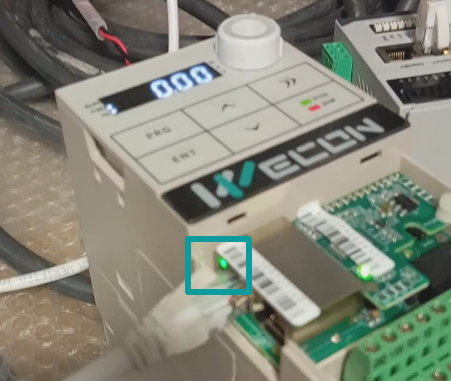
After connecting to the PLC, if the connection is successful, LED5 blinks rapidly; otherwise, LED5 blinks at a slow rate or the status remains unchanged.
Operation
You can download the module's XML file here. VC EtherCAT xml
Then import it to PLC software. The following is the table for the PDO.
| RPDO1 | The command from AC Driver | 01:Running forward 02: Running reverse 03:Positive turn point stop 04: Reverse the dots 05: Free stop 06: Slow down & stop 07: Reset the fault |
| RPDO2 | AC Driver’s target frequency | -10000~10000 (-10000 for -100% 10000 for 100%) |
| TPDO1 | AC Driver state | 01: Running forward 02: Running reverse 03: Standby 04: Fault 05: Under-voltage 06: Direction switching |
| TPDO2 | Running frequency(Hz) | 0.01Hz |
| TPDO3 | Setting frequency(Hz) | 0.01Hz |
| TPDO4 | Bus voltage(V) | 0.1V |
| TPDO5 | Output voltage(V) | 1V |
| TPDO6 | Bus current(A) | 0.1A |
| TPDO7 | Output power(kW) | 0.1% |
| TPDO8 | Output torque(%) | 0.1% |
| TPDO9 | DI Input state | |
| TPDO10 | DO Output state |
Problem
1. If the LED light status is normal, but after writing the frequency or control word, the inverter's status did not change.
To operate the frequency converter in EtherCAT mode, set F0.01 = 2 and F0.03 = 9.
2. If the LED light status is normal, but the value of bus voltage did not change.