04 Display & Operation
Last modified by Wecon on 2025/09/03 21:04
Display introduction
With the keypad, you can modify the function parameters of the inverter, monitor the working status of the inverter and control the operation of the inverter (start and stop). Its appearance and function area are shown in the following figure:
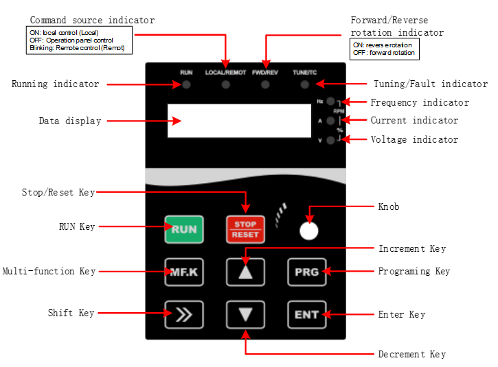
Figure 3-1-1 Keypad diagram
Description of indicators and keys
| Item | Name | Function |
| Indicator | Unit indicators | Hz: Unit of frequency; A:Unit of current; V:Unit of voltage; RPM(Hz+A): Unit of rotational speed; %(A+V): Percentage |
| Status | RUN: ON/Running; OFF/Stop FWD/REV: ON/Forward rotation; OFF/Reverse rotation; Blinking/Forward and reverse switching TUNE/TC: Blinking slowly/Auto-tuning state; Blinking quickly/Fault state; LOCAL/REMOTE: ON/Terminal control;Blinking/Communication; OFF/keypad control | |
| Key | PRG (Programming) | Enter or exit the first menu. |
| ENT (Confirm) | Enter the menu interfaces and confirm the parameter setting. | |
| △(Increment) | Increase date or function code. | |
| ▽(Decrement) | Decrease data or function code. | |
| >>(Shift) | Select the displayed parameters in the stop or running state and select the digit to be modified when modifying parameters. | |
| RUN | Start the AC Drive in keypad control mode. | |
| STOP/RESET | Stop the AC Drive when it is in the running state and perform the reset operation when it is in the fault state. The functions of this key are restricted in F7.02. | |
MF.K (Multi-functional choice) | Perform function switchover according to the setting of F7.01. | |
| Knob | Pulse potentiometer | Can be used as frequency source.When used as a frequency source, clockwise rotation increases the frequency and counterclockwise rotation decreases the frequency. |
Table 3-2-1 Description of Indicators and key