F0 group basic function group
| F0.00 | Motor control mode | Factory default | 1 |
| Setting range | 0: Speed sensorless vector control (SVC) 1: V/F control | ||
0: Speed sensorless vector control
Refers to an open loop vector. Suitable for the usual high-performance control occasions, one inverter can only drive one motor. Such as machine tools, centrifuges, wire drawing machines, injection molding machines and other loads.
1: V/F control
It is suitable for occasions where the load requirement is not high or a VFD drags multiple motors, such as fans and pumps. It can be used for driving multiple motors with one VFD.
Tip: When selecting the vector control mode, the motor parameter identification process must be carried out. Only accurate motor parameters can give full play to the advantages of vector control.
| F0.01 | Command source selection | Factory default | 0 |
| Setting range | 0: Operation panel command channel 1: Terminal command channel 2: Serial port communication command channel | ||
Select the channel for the inverter control command.
Inverter control commands include: start, stop, forward, reverse, point and so on.
0: Operation panel command channel
The command is controlled by the key on the operation panel.
1: Terminal command channel
It is controlled by the multi-function input terminals FWD, REV, FJOG, RJOG, etc.
2: Serial port communication command channel
The host computer gives the running command control through the communication mode.
| F0.02 | Run time UP/DOWN benchmark | Factory default | 1 |
| Setting range | 0: Operating frequency 1: Setting frequency | ||
This function only effective for frequency source digital setting, in order to determine the setting frequency of UP/DOWN is current running frequency or current setting frequency.
| F0.03 | Main frequency source X choice | Factory default | 4 |
| Setting range | 0: Digital setting F0.08 (Adjustable terminal UP/DOWN, be not retained at power failure) 1: Digital setting F0.08 (Adjustable terminal UP/DOWN, be retained at power failure) 2: AI1 3: AI2 4: Keyboard potentiometer set 5: Set the terminal PULSE 6: Multi-speed instruction 7: Simple PLC 8: PID 9: Communication settings 10: AI3(Expansion module) | ||
Select the input channel for the main given frequency of the inverter. There are 10 main given frequency channels:
0: Digital setting (no memory) (Potentiometer and terminal UP/DOWN adjustable, power failure no memory) The initial value is F0.08 value of Digital Setting Preset Frequency. The set frequency value of the inverter can be changed by ▲/▼ key of the keyboard (or the UP and DOWN of the multi-function input terminal). No memory means that after the inverter power off, the set frequency value is restored to the initial value;
1: Digital setting (memory) (Potentiometer and terminal UP/DOWN adjustable, power failure memory) The initial value is F0.08 "digital setting preset frequency" value. The set frequency value of the inverter can be changed by ▲/▼ key of the keyboard (or the UP and DOWN of the multi-function input terminal). Memory means that when the inverter is powered on again after power failure, the set frequency is the set frequency before the last power failure
2: AI1 3: AI2 refers to the frequency determined by the analog input terminal. The standard unit provides two analog input terminals (AI1, AI2), of which AI1 is 0V to 10V voltage input, AI2 can be 0V to 10V voltage input, or 4mA to 20mA current input.
4: Potentiometer set by keyboard potentiometer to set the frequency
5: PULSE pulse setting (DI4) The frequency setting is set by the terminal pulse. Pulse given signal specifications: voltage range, frequency range 0kHz to 20kHz. Note: Pulse Settings can only be input from the multi-function input terminal DI4.
6: Multi-speed Select the multi-speed operation mode. The F5 "input terminal" and FD "multi-speed and PLC" parameters need to be set to determine the correspondence between a given signal and a given frequency.
7: Simple PLC Select simple PLC mode. When the frequency source is a simple PLC, the FD group "multi-speed and PLC" parameters need to be set to determine the given frequency.
8: PID selection process PID control. In this case, set the PID function of the F9 group. The operating frequency of the inverter is the frequency value after PID action. For the meaning of PID set source, feed quantity and feedback source, please refer to the introduction of F9 group "PID Function".
9: Communication set means that the main frequency source is given by the host computer through communication.
| F0.04 | Auxiliary frequency source Y selection | Factory default | 4 |
| Setting range | 0: Numeric setting F0.08 (Terminal UP/DOWN can be change, Power failure does not remember. It is cleared after switching as a frequency source.) 1: Numeric setting F0.08 (Terminal UP/DOWN adjustable, be retained at power failure.) 2: AI1 given 3: AI2 given 4: Keyboard potentiometer set. 5: The terminal PULSE pulse is set. 6: Multi-speed instruction 7: Simple PLC 8: PID 9: Communication setting | ||
The secondary frequency source Y is used in the same way as the primary frequency source X when it is used as an independent frequency given channel (that is, the frequency source selected to switch from X to Y).
| F0.05 | The auxiliary frequency source Y range is selected during superposition | Factory default | 0 |
| Setting range | 0: Relative to the maximum frequency F0.10 1: Relative to the frequency source X | ||
| F0.06 | Auxiliary frequency source Y range in superposition | Factory default | 100% |
| Setting range | 0% to 150% | ||
When the frequency source is selected as a frequency stack (F0.07 is set to 1, 3, or 4), it is used to determine the adjustment range of the auxiliary frequency source. F0.05 is used to determine the object relative to the range, if it is relative to the maximum frequency (F0.10), the range is a fixed value; If it is relative to the primary frequency source X, its range will change as the primary frequency source X changes.
| F0.07 | Frequency source stack selection | Factory default | 0 |
| Setting range | LED bits: Frequency source selection 0: Primary frequency source 1: Results of primary and secondary operations 2: Master-auxiliary switching 3: Switch between primary frequency source and operation result 4: Switch between primary frequency source and operation result LED ten: combination mode selection 0: Primary + Auxiliary 1: Master-auxiliary 2: Maximum value of both 3: Minimum of both 4: Main x auxiliary | ||
The secondary frequency source is used in the same way as the primary frequency source X when it is used as an independent frequency given channel (that is, the frequency source selected is switched from X to Y). When the secondary frequency source is used as a superposition given (i.e., the frequency source selected is X+Y, X to X+Y switching, or Y to X+Y switching), there are the following special features:
When the auxiliary frequency source for digital or pulse potentiometer timing, preset frequency (F0.08) does not work, through the keyboard ▲/▼ key (or multi-function input terminal UP, DOWN) can be adjusted on the basis of the main given frequency.
When the auxiliary frequency source is given as an analog input (AI1, AI2) or a pulse input, 100% of the input setting corresponds to the auxiliary frequency source range (see F0.05 and F0.06 instructions). If you need to adjust up or down from the main given frequency, set the analog input to a range of n% to +n%.
The frequency source is timed for pulse input, similar to analog quantity setting.
Tip: The secondary frequency source Y and the primary frequency source X Settings cannot be the same, that is, the primary and secondary frequency sources cannot use the same frequency given channel.
| F0.08 | Keyboard setting frequency | Factory default | 50.00Hz |
| Setting range | 0.00 to Maximum frequency F0.10 | ||
When the frequency source is selected “Numeric setting F0.08 (Terminal UP/DOWN Adjustable, power down memory) ", the function code value sets the initial value for the frequency number of the inverter.
| F0.09 | Running direction selection | Factory default | 0 |
| Setting range | 0: The same direction 1: The direction is reversed 2: Reverse prohibition | ||
By changing the function code, the steering of the motor can be changed without changing any other parameters, which is equivalent to the conversion of the rotation direction of the motor by adjusting any two lines of the motor (U, V, W).
Tip: The motor running direction will be restored to the original state after parameter initialization. For the system debugging is strictly prohibited to change the motor steering occasions with caution.
| F0.10 | Maximum output frequency | Factory default | 50.00 Hz |
| Setting range | 0.00 to 320.00Hz | ||
When F0.26=1, the upper limit of the maximum frequency is 1000Hz. When F0.26=2, the upper limit of the maximum frequency is 320Hz.
| F0.11 | Upper limit frequency source selection | Factory default | 0 |
| Setting range | 0: The number is F0.12 1: AI1 2: AI2 3: AI3(Expansion module) 4: Set the terminal PULSE 5: Communication given 6: Reserved 7: Keyboard potentiometer set | ||
Define the source of the upper limit frequency.
0: Number setting (F0.12).
1/2/3: Analog input channel. When setting an upper limit frequency with an analog input, 100% of the analog input setting corresponds to F0.12.
4: Set by terminal pulse.
5: Communication given 10000 corresponds to F0.12.
7: Set by keyboard potentiometer.
For example, in torque control, speed control is not effective. In order to avoid the "speed" of material breakage, the upper limit frequency can be set with the analog quantity. When the inverter runs to the upper limit frequency value, the torque control is invalid and the inverter continues to run at the upper limit frequency.
| F0.12 | Upper limit frequency | Factory default | 50.00Hz |
| Setting range | Lower frequency F0.14 to Maximum frequency F0.10 | ||
| F0.13 | Upper frequency bias | Factory default | 0.00Hz |
| Setting range | 0.00Hz to Maximum frequency F0.10 | ||
When the upper limit frequency is given by the analog quantity, this parameter is used as the bias quantity calculated by the upper limit frequency, and this upper limit frequency offset is added to the set value of the upper limit frequency of the simulation as the set value of the final upper limit frequency.
| F0.14 | Lower frequency | Factory default | 0.00Hz |
| Setting range | 0.00Hz to Upper limit frequency F0.12 | ||
When the VFD starts to run, it starts from the start frequency. If the given frequency is less than the lower limit frequency during operation, the VFD runs at the lower limit frequency, stops or runs at zero speed. You can set which mode of operation to use with F0.15.
| F0.15 | Lower frequency Operating mode | Factory default | 0 |
| Setting range | 0: Run at the lower limit frequency 1: Stop 2: Zero speed operation | ||
Select the operating state of the inverter when the set frequency is lower than the lower limit frequency. In order to avoid the motor running at low speed for a long time, you can use this function to choose to stop.
| F0.16 | Carrier frequency | Factory default | Model determination |
| Setting range | 0.5kHz to 16.0kHz | ||
This function regulates the carrier frequency of the inverter. By adjusting the carrier frequency, the motor noise can be reduced, the resonance point of the mechanical system can be avoided, and the interference of the line to the floor drain current and the VFD can be reduced.
When the carrier frequency is low, the higher harmonic component of the output current increases, the motor loss increases, and the motor temperature rise increases.
When the carrier frequency is high, the motor loss decreases and the motor temperature rise decreases, but the VFD loss increases, the VFD temperature rise increases and the interference increases.
The effect of adjusting the carrier frequency on the following performance:
| Carrier frequency | Low  High High |
| Motor noise | High  Low Low |
| The output current waveform | Worse  Better Better |
| Temperature rise in electric motors | High  Low Low |
| VFD temperature rise | Low  High High |
| Leak current | Low High High |
| External radiation interference | Low High High |
| F0.17 | Carrier PWM baud selection | Factory default | 1010 |
| Setting range | Bits: Select PWM mode 0: Automatic switching; 1: 7 wave; 2: 5 wave; 3: SPWM; LED ten: Carrier is associated with the output frequency 0: Independent of the output frequency 1: Related to the output frequency LED hundred: random PWM depth 0: Off 1-8: Open and adjust the depth LED kilobit: Over modulation option 0: Off 1: On | ||
| F0.18 | Acceleration time 1 | Factory default | Model determination |
| Setting range | 0.0s to 6500.0s | ||
| F0.19 | Deceleration time1 | Factory default | Model determination |
| Setting range | 0.0s to 6500.0s | ||
One place: Select PWM mode
VFD can choose 5-section wave or 7-section wave, the 5-section wave converter has little heat, and the 7-section wave motor has little noise. When the bit is 0, 7 waves are generated at low frequency and 5 waves are generated at high frequency. At 1 o 'clock, the whole wave is 7 stages, and at 2 o'clock, the whole wave is 5 stages.
Tens place: The carrier is associated with the output frequency
When the output frequency is low, reducing the PWM carrier can increase the low frequency starting torque and reduce the electromagnetic interference during starting. When the bit is 1, the program automatically reduces the PWM carrier when the output frequency is low.
Hundreds place: Random PWM depth
In order to make the motor noise spectrum flatter, you can turn on the random PWM function, after the function is turned on, the PWM carrier is no longer a fixed value, but fluctuates around the F0.16 set carrier. When the bit is not 0, the random PWM function works. The larger the value, the wider the fluctuation range and the flatter the noise spectrum. It should be noted that after opening the random carrier, the electromagnetic noise of the motor will not necessarily be reduced, and the actual noise perception varies from person to person.
Thousands place: Over modulation option
The over modulation function can increase the maximum output voltage of the inverter, but it also makes the current distortion more obvious. When the bit is 1, the over modulation function is enabled.
Acceleration time refers to the time required for the inverter to accelerate from zero frequency to the reference frequency of acceleration and deceleration (determined by F0.24), as shown in t1 in Figure 9-0-1.
Deceleration time refers to the time required for the VFD to decelerate from the reference frequency of acceleration and deceleration (determined by F0.24) to the zero frequency, see t2 in Figure 9-0-1.

Figure 9-0-1 Acceleration and deceleration time
Note the difference between the actual acceleration and deceleration time and the set acceleration and deceleration time.
There are four groups of acceleration and deceleration time selection
Group 1: F0.18, F0.19;
Group 2: F8.03, F8.04;
Group 3: F8.05, F8.06;
Group 4: F8.07, F8.08.
The acceleration and deceleration time can be selected through the multifunctional digital input terminals (F5.00 to F5.03).
| F0.20 | Parameter initialization | Factory default | 0 |
| Setting range | 0: No operation 1: Restore factory default (Do not restore motor parameters) 2: Clear the record information 3: Restore factory default (Restore motor parameters) | ||
1: Restore factory settings, excluding motor parameters
2: Clear recorded information, clear the VFD fault record, cumulative running time (F7.09), cumulative power-on time (F7.13),
Cumulative power consumption (F7.14).
3: Restore all factory settings, including motor parameters, and clear the recorded information at the same time.
| F0.23 | Unit of acceleration and deceleration time | Factory default | 1 |
| Setting range | 0: 1s 1: 0.1s 2: 0.01s | ||
This function is used to determine all acceleration and deceleration time units.
Note that when the value is modified, the actual acceleration and deceleration time will also change accordingly (the decimal point position changes, the actual display number remains unchanged), Therefore, it is necessary to adjust the various acceleration and deceleration Settings according to the situation.
Note the following function codes: F0.18, F0.19, F8.01, F8.02, F8.03, F8.04, F8.05, F8.06, F8.07, F8.08.
| F0.24 | Acceleration and deceleration time reference frequency | Factory default | 0 |
| Setting range | 0: Maximum frequency (F0.10) 1: Set the frequency 2: 100 Hz | ||
Define the frequency range corresponding to the acceleration and deceleration time. See Figure 9-0-1 Acceleration and deceleration time.
| F0.25 | Fan control | Factory default | 01 |
| Setting range | One place: Start/stop control 0: The fan runs after the inverter is powered on 1: Shutdown is related to temperature, and operation is running 2: Stop The fan stops and the operation is temperature-related Tens place: Enables the speed adjustment function 0: Off 1: Enable | ||
1: Start-stop control: After startup, the device runs. If the temperature is above 50 degrees when stopped, it continues to run.
2: Temperature control: More than 50 degrees to start operation
Tens place: Enables the speed adjustment function
Speed control: Below 45°C: Operate at 50% speed; From 45°C to 50°C: Operate at 75% speed; At 50°C and above: Operate at 100% speed.
| F0.26 | Frequency command decimal point | Factory default | 2 |
| Setting range | 1: 1 decimal places 2: 2 decimal places | ||
This parameter is not restored when restoring factory defaults.
| F0.27 | Modulation ratio coefficient | Factory default | 100.0% |
| Setting range | 10.0 to 150.0% | ||
This parameter is the upper limit of the modulation ratio. The lower the modulation ratio, the lower the maximum output voltage; The higher the modulation ratio, the more obvious the current distortion during over modulation.
F1 group start stop control
| F1.00 | Start-up operation mode | Factory default | 00 |
| Setting range | LED ones place: Boot mode 0: Start directly from the start frequency 1: Start after speed tracking and direction judgment 2: The asynchronous machine starts with pre-excitation | ||
0: Direct startup
1: Start after speed tracking and direction judgment
The inverter first detects the steering and speed of the motor, and then starts according to the real-time speed. It is suitable for instantaneous power failure and restart of large inertia load or smooth restart of rotating equipment. Set accurate F2 motor parameters for better speed tracking and restart performance.
2: The asynchronous machine starts with pre-excitation
Pre-excitation current, time and DC braking current, time share function code. If F1.09 pre-start braking time is set to 0, start from the start frequency. When the value is not set to 0, pre-excitation is implemented before startup to improve the dynamic response speed.
| F1.01 | Speed tracking mode | Factory default | 0 |
| Setting range | LED tens place: speed tracking direction 0: One to the stop direction 1: One to the starting direction 2: Automatic search | ||
Ten: speed tracking direction
This parameter determines the direction from which to start speed tracking. Please set it correctly according to the actual situation. If the setting is wrong, the startup may fail. In the case of not knowing the starting direction, you can set to automatic search, the program will automatically judge the starting direction, but the search time will be lengthened accordingly.
| F1.02 | Speed tracking time | Factory default | 1.00s |
| Setting range | 0.01 to 60.00s | ||
If the speed tracking time is too short, the tracking may end without tracking the actual frequency. At F1.01=002X, if the search direction is wrong, two searches will be performed and the actual search time will be doubled.
| F1.03 | Speed tracking current loop gain | Factory default | 10.00 |
| Setting range | 0.00 to 10.00 | ||
| F1.04 | RPM tracking speed gain | Factory default | 2.00 |
| Setting range | 0.01 to 10.00 | ||
The excitation search current loop gain and velocity loop gain are determined.
| F1.05 | Speed tracking current | Factory default | 150% |
| Setting range | 50% to 200% | ||
Set the excitation search current size.
| F1.06 | Starting frequency | Factory default | 0.00Hz |
| Setting range | 0.0s to 60.00Hz | ||
| F1.07 | Startup frequency duration | Factory default | 0.0s |
| Setting range | 0.0 to 50.0s | ||
In order to ensure the torque during startup, please use the appropriate startup frequency. In addition, the magnetic flux is established when waiting for the motor to start, so that the starting frequency is maintained for a certain time before accelerating. The starting frequency is maintained for a certain time before accelerating. The startup frequency F1.06 is not limited by the lower frequency. If the frequency given less than startup frequency, the AC driver can no be started, and it will standby state. The startup frequency holding time is not work during forward/reverse switching. The holding time is not included in the acceleration time, but is included in the running time of the simple PLC.
| F1.08 | Braking current before starting | Factory default | 80.0% |
| Setting range | 0.0 to 150.0% | ||
| F1.09 | Braking time before starting | Factory default | 0.0s |
| Setting range | 0.0 to 60.0s | ||
Starting DC braking is generally used to stop the motor completely before starting.
If the starting mode is starting after the DC braking, the AC driver will execute the DC braking as the setting value, and it will start running after the setting starting braking time value. It will direct start without DC braking if the setting DC braking time is 0. The braking power is greater with the greater DC braking current.
| F1.10 | Shutdown mode | Factory default | 0 |
| Setting range | 0: Slow down stop 1: Free stop | ||
0: Slow down stop
After the stop command is effective, the inverter reduces the output frequency according to the deceleration mode and the defined acceleration and deceleration time, and stops after the frequency drops to 0.
1: Free stop
When the stop command is valid, the inverter terminates output immediately. The load stops freely according to mechanical inertia.
| F1.11 | Stop DC braking start frequency | Factory default | 0.00Hz |
| Setting range | 0.00Hz to Maximum frequency F0.10 | ||
| F1.12 | Stop DC braking wait time | Factory default | 0.0s |
| Setting range | 0.0s to 100.0s | ||
| F1.13 | Stop DC braking current | Factory default | 80.0% |
| Setting range | 0% to 150% | ||
| F1.14 | Stop DC braking duration | Factory default | 0.0s |
| Setting range | 0.0s to 100.0s | ||
DC braking start frequency: slow down the stopping process. When the output frequency is less than this frequency, the DC braking process starts to stop.
DC braking waiting time: When the output frequency is reduced to F1.11 DC braking starting frequency, the inverter stops output and starts timing. After the delay time set by F1.12, DC braking starts again. Used to prevent over current failure caused by DC braking at high speeds.
Stop DC braking current: refers to the amount of DC braking applied. The greater the value, the stronger the DC braking effect.
DC braking time: the time added to the DC braking amount. When this value is 0, it means that there is no DC braking process, and the inverter stops according to the set deceleration stop process.
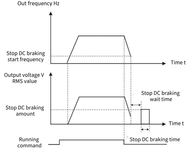
Figure 9-1-1 Shutdown DC braking diagram
| F1.16 | Energy consumption brake action voltage | Factory default | Model-based setting |
| Setting range | 115.0% to 140.0% | ||
Set the brake resistance operating voltage. When the relative value of the bus voltage is higher than this value, the brake resistance starts braking.
| F1.17 | Magnetic flux braking gain | Factory default | 80% |
| Setting range | 10% to 500% | ||
| F1.18 | Magnetic flux braking operating voltage | Factory default | Model-based setting |
| Setting range | 110% to 150% | ||
| F1.19 | Flux brake limiting | Factory default | 20% |
| Setting range | 0 to 200% | ||
When the motor decelerates the feedback energy, opening the flux brake can consume the feedback energy on the motor, so as to achieve rapid deceleration of the motor. This function is only effective in asynchronous motor VF control, and turning on this function will correspondingly increase motor loss and motor temperature rise.
Magnetic flux braking gain: The strength of magnetic flux braking, the greater the parameter, the greater the magnetic flux braking current.
Magnetic flux braking action voltage: When the relative value of the bus voltage is higher than this value, magnetic flux braking begins to work.
Flux brake limiting: The upper limit of the flux brake voltage, which may cause the output current of the inverter to be too high.
| F1.20 | Acceleration and deceleration selection | Factory default | 0 |
| Setting range | 0: Straight line 1: S curve | ||
0: Straight line, generally suitable for general purpose load.
1: S-curve, S-type acceleration and deceleration curve is mainly provided for the load that needs to slow down noise and vibration during acceleration and deceleration, reduce start-stop impact, or decrease torque at low frequency, and short-time acceleration at high frequency. If an over current or over load failure occurs at startup, reduce the set value of [F1.21].
| F1.21 | S-curve initial acceleration rate | Factory default | 50.0% |
| Setting range | 20.0% to 100.0% | ||
| F1.22 | S-curve initial deceleration rate | Factory default | 50.0% |
| Setting range | 20.0% to 100.0% | ||
S-curve Initial acceleration rate: The rate at which the acceleration process begins to increase in frequency. The smaller the initial acceleration rate, the more curved the S-curve of the acceleration process, whereas the larger the initial acceleration rate, the closer the acceleration S-curve to a straight line. To make the acceleration curve softer, you can reduce the initial acceleration rate and extend the acceleration time.
| F1.23 | Zero speed holding torque | Factory default | 0 |
| Setting range | 0.0% to 150.0% | ||
Set the output torque of the inverter at zero speed. If the torque setting is large or the duration is long, attention should be paid to the heat dissipation of the motor.
| F1.24 | Zero speed holding torque time | Factory default | Model setting |
| Setting range | 0.0 to 6000.0s If the value is set to 6000.0s, the value remains unchanged without time limitation | ||
Set the torque holding time when the inverter is running at zero speed. The timing starts when the operating frequency is 0Hz, and the inverter stops output after the time reaches the set zero-speed holding torque time. Among them, the effective timing value is 0 to 5999.9s, and the parameters are set in the effective timing value of the VFD at the set time. After the time is full, the VFD terminates and maintains the zero-speed torque.
If the parameter setting is equal to 6000.0s, the VFD is not timed and defaults to long-term validity, and the zero-speed torque holding is terminated only after the stop command is given or the non-zero operating frequency is given.
Setting an appropriate zero-speed holding torque time can effectively achieve energy saving and protect the motor.
| F1.25 | Start pre-excitation time | Factory default | 0.20 |
| Setting range | 0.00 to 60.00s | ||
This parameter is only valid if F0.00=0, in the open loop vector start, appropriate pre-excitation can make the start smoother.
| F1.26 | Shutdown frequency | Factory default | 0.00Hz |
| Setting range | 0.00 to 60.00Hz | ||
This function is defined as the frequency of the minimum output of the inverter, less than this frequency, the output of the inverter stops.
| F1.27 | Power failure restart action selection | Factory default | 0 |
| Setting range | 0: Invalid 1: Valid | ||
0: Invalid VFD power after power failure must receive the operation instruction before running.
1: Valid If the inverter is in operation before the power is cut off, the inverter will automatically start after the power is restored and after the set waiting time (set by [F1.28]). During the waiting time of power failure and restart, the inverter does not accept the running command, but if the stop command is entered during this period, the inverter will release the restart state.
| F1.28 | Power failure restart waiting time | Factory default | 0.50s |
| Setting range | 0.00 to 120.00s | ||
When [F1.27] setting is effective, After the inverter power supply, it will wait for the time set in [F1.28] to start running.
| F1.29 | Select the terminal running protection | Factory default | 11 |
| Setting range | LED units digital: Select the terminal run instruction when powering on. 0: The terminal running instruction is invalid during power-on. 1: Terminal running instructions are valid during power-on. LED tens place: Run instruction given channel switch terminal run instruction selection. 0: The terminal running instruction is invalid. 1: The terminal instruction is valid when the terminal is cut in. | ||
When terminal operation is selected, the initial wiring state of peripheral devices may affect the safety of the device. This parameter provides protective measures for terminal operation.
LED units place: Select the terminal run command when powering on
Select the mode of executing the operation instruction when the inverter is powered on with the terminal running signal in effect.
0: The terminal instruction is invalid during power-on. The terminal control stops before the power is started.
1: When the terminal is powered on, the terminal control instruction is valid.
LED tens place: Terminal run instruction selection when switching to terminal instruction from other instruction channels
Select the mode of running the instruction channel to switch to the terminal instruction mode and execute the running instruction when the terminal running signal is valid.
0: The terminal running instruction is invalid when cutting in. The terminal control stops before starting.
1: When the terminal instruction is effective, the terminal control can be started directly.
F2 group motor parameters
| F2.00 | Motor type | Factory default | 0 |
| Setting range | 0: Asynchronous motor (AM) 1: Permanent magnet synchronous motor (PM) 2: Single-phase asynchronous motors (Only VF control is supported) | ||
2 Single-phase asynchronous motor refers to a single-phase motor without phase shift capacitance, U terminal is connected to the main winding, V terminal is connected to the common end, and W terminal is connected to the auxiliary winding.
| F2.01 | Rated power of motor | Factory default | Model determination | ||||
| Setting range | 0.1kW to 400.0kW | ||||||
| F2.02 | Rated voltage of motor | Factory default | Model determination | ||||
| Setting range | 1V to 440V | ||||||
| F2.03 | Rated current of motor | Factory default | Model determination | ||||
| Setting range | 0.1A to 2000.0A | ||||||
| F2.04 | Rated power of motor | Factory default | Model determination | ||||
| Setting range | 0.00Hz to Maximum frequency F0.10 | ||||||
| F2.05 | Rated motor speed | Factory default | Model determination | ||||
| Setting range | 1rpm to 65000rpm | ||||||
| ✎Note: 1. Please set according to the nameplate parameters of the motor. 2. The excellent control performance of vector control requires accurate motor parameters, and accurate parameter identification comes from the correct setting of the rated parameters of the motor. 3. In order to ensure the control performance, please configure the motor according to the inverter standard adaptation motor, if the motor power and the standard adaptation motor gap is too large, the control performance of the inverter will be significantly reduced. | |||||||
| F2.06 | Motor stator resistance | Factory default | Model determination | ||||
| Setting range | 0.001Ω to 65.000Ω | ||||||
| F2.07 | Motor rotor resistance | Factory default | Model determination | ||||
| Setting range | 0.001Ω to 65.000Ω | ||||||
| F2.08 | Motor fixed rotor inductance | Factory default | Model determination | ||||
| Setting range | 0.1 to 6500.0mH | ||||||
| F2.09 | Mutual inductance of motor fixed rotor | Factory default | Model determination | ||||
| Setting range | 0.1 to 6500.0mH | ||||||
| F2.10 | Motor no-load current | Factory default | Model determination | ||||
| Setting range | 0.1 to 650.0A | ||||||
After the automatic tuning of the asynchronous motor is completed normally, the set values of the asynchronous motor parameters (F2.06 to F2.10) are automatically updated.
After changing the motor rated power F2.01 each time, the VFD F2.06 to F2.10 parameter values will automatically restore the default standard motor parameters, if running in vector mode, please re-tune.
| F2.11 | Tuning selection | Factory default | 0 |
| Setting range | 0: No operation is performed 1: Static tuning 1 2: Full tuning 3: Static tuning 2 (AM calculated Lm) | ||
Tip: Before tuning, you must set the correct motor type and rating parameters (F2.00 to F2.05).
0: No operation is performed, that is, tuning is disabled.
1: Static tuning 1, suitable for the motor and the load is not easy to come off and can not be rotated tuning occasions, static tuning learning asynchronous motor F2.05-F2.10 or synchronous motor F2.22 to F2.25 parameters, wherein synchronous motor back potential is calculated according to F2.01 and F2.03, if the motor power or current and the actual difference is large, Calculations may not be accurate.
Action description: Set the function code to 1, and press the RUN key to confirm, the inverter will perform static tuning.
2: Complete tuning, in order to ensure the dynamic control performance of the inverter, please select rotary tuning, rotary tuning motor must be disconnected from the load (no-load). After selecting rotary tuning, the inverter first performs static tuning, and after static tuning, the motor accelerates to 80% of the rated frequency of the motor, and maintains it for a period of time, and then decelerates and stops, and the rotary tuning ends.
Action description: Set the function code to 2, and press the RUN key to confirm, the inverter will perform rotation tuning.
3: Static tuning 2, different from static tuning 1, the tuning needs to manually input the asynchronous motor no-load current F2.10, the program will calculate the mutual inductance F2.09 according to the current, the other is the same as static tuning 1.
Action description: Set the function code to 3, and press the RUN key to confirm, the inverter will perform static tuning.
Note: Tuning can only be effective in keyboard control mode, acceleration and deceleration time is recommended to use the factory default.
| F2.12 | G/P Machine type | Factory default | Model determination |
| Setting range | 0: G-type machine; 1: P-type machine | ||
This parameter can only be used to view factory models.
1: Constant torque load for specified rated parameters.
2: Suitable for the specified rated parameters of the variable torque load (fan, pump load).
| F2.13 | Single phase asynchronous motor turns ratio | Factory default | 100% |
| Setting range | 10 to 200% | ||
U terminal main winding, V terminal auxiliary winding, W common end, this parameter is used to set the ratio of the number of turns between the main winding and the auxiliary winding of the single-phase motor.
| F2.14 | Current calibration coefficient of single-phase motor | Factory default | 120% |
| Setting range | 50 to 200% | ||
The single-phase motor has main and auxiliary windings, and the three-phase output current is unbalanced, so the output current displayed by the inverter needs to be multiplied by the coefficient of the resultant current.
| F2.15 | Number of motor poles | Factory default | 4 |
| Setting range | 2 to 48 | ||
Change F2.04 or F2.05, the program will automatically calculate the number of motor poles, in general, do not need to set this parameter.
| F2.22 | Stator resistance of synchro | Factory default | Model determination |
| Setting range | 0.001 to 65.000(0.001Ohm) | ||
| F2.23 | Synchro d-axis inductance | Factory default | Model determination |
| Setting range | 0.01mH to 655.35mH | ||
| F2.24 | Synchro Q-axis inductance | Factory default | Model determination |
| Setting range | 0.01mH to 655.35mH | ||
| F2.25 | Synchro back electromotive force | Factory default | Model determination |
| Setting range | 0.1V to 1000.0V | ||
After the automatic tuning of the synchronous motor is completed, the set values of the synchronous motor parameters (F2.22 to F2.25) are automatically updated.
After changing the rated motor power F2.01 each time, the F2.22 to F2.25 parameter values of the inverter will automatically restore the default standard motor parameters, please re-tune.
| F2.28 | High frequency injection voltage | Factory default | 20.0% |
| Setting range | 0.1% to 100.0% | ||
The current injected when the synchronous motor learns the inductance of DQ axis by high frequency injection.
| F2.29 | Back potential identification current | Factory default | 50.0% |
| Setting range | 0.1% to 100.0% | ||
The output current of the inverter is the size when the synchronous motor dynamically adjusts to learn the back potential.
| F2.31 | Asynchronous no-load current per unit value | Factory default | Model determination |
| Setting range | 0.1% | ||
| F2.32 | Per unit asynchronous stator resistance | Factory default | Model determination |
| Setting range | 0.01% | ||
| F2.33 | Asynchronous rotor resistance per unit value | Factory default | Model determination |
| Setting range | 0.01% | ||
| F2.34 | Asynchronous mutual inductance per unit value | Factory default | Model determination |
| Setting range | 0.1% | ||
| F2.35 | Asynchronous leakage sensing per unit value | Factory default | Model determination |
| Setting range | 0.01% | ||
| F2.36 | Per unit value of asynchronous leakage sensing coefficient | Factory default | Model determination |
| Setting range | 0.01% | ||
| F2.37 | Synchronous stator resistance per unit value | Factory default | Model determination |
| Setting range | 0.01% | ||
| F2.38 | Per unit value of synchronous D-axis inductance | Factory default | Model determination |
| Setting range | 0.01% | ||
| F2.39 | Synchronous Q-axis inductance per unit value | Factory default | Model determination |
| Setting range | 0.01% | ||
| F2.40 | Back electromotive force of synchronous motor | Factory default | Model determination |
| Setting range | 0.1V | ||
The per unit value of the motor parameters is used for the actual program calculation. After learning or parameter recovery, the actual change is F2.31 to F2.40. F2.06 to F2.10 and F2.22 to F2.25 are calculated from the per unit value, so only F2.31 to F2.40 values can be modified, F2.06 to F2.10 and F2.22 to F2.25 are only used to display and cannot be changed.
F3 vector control parameters
The F3 group function code is only valid in vector control mode, that is, it is valid when F0.00 = 0 and invalid when F0.00 = 1.
| F3.00 | ASR (Speed loop) proportional gain 1 | Factory default | 0.20 |
| Setting range | 0.00 to 1.00 | ||
| F3.01 | ASR(Velocity ring) integration time 1 | Factory default | 0.20 |
| Setting range | 0.01 to 10.00s | ||
| F3.03 | ASR filtering time 1 | Factory default | 0.000s |
| Setting range | 0.000 to 0.100s | ||
| F3.04 | ASR switching frequency 1 | Factory default | 5.00Hz |
| Setting range | 0.00 to 50.00Hz | ||
| F3.05 | ASR(Speed loop) proportional gain 2 | Factory default | 0.20 |
| Setting range | 0.00 to 1.00 | ||
| F3.06 | ASR(Velocity loop) integration time 2 | Factory default | 0.20 |
| 0.01 to 10.00s | |||
| F3.08 | ASR filtering time 2 | Factory default | 0.000s |
| Setting range | 0.000 to 0.100s | ||
| F3.09 | ASR switching frequency 2 | Factory default | 10.00Hz |
| Setting range | 0.00 to 50.00Hz | ||
F3.00 and F3.01 are PI adjustment parameters when the operating frequency is less than switching frequency 1 (F3.04).
F3.05 and F3.06 are PI adjustment parameters whose operating frequency is greater than switching frequency 2 (F3.09).
The PI parameters of the frequency segment between switching frequency 1 and switching frequency 2 are linear switching of the two groups of PI parameters, as shown in the figure below:
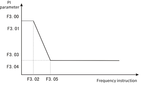
Figure 9-3-1 PI parameter diagram
The speed dynamic response characteristic of vector control can be adjusted by setting the proportional coefficient and integration time of the speed regulator. Proportional increase
If the integration time is reduced, the dynamic response of the speed loop can be accelerated. The system may oscillate if the proportional gain is too large or the integration time is too small.
Recommended adjustment method:
If the Factory parameters cannot meet the requirements, fine-tune the Factory default parameters: first increase the proportional gain to ensure that the system does not oscillate; Then the integration time is reduced so that the system has both faster response characteristics and smaller overshoot.
Note: Setting the PI parameter incorrectly may result in excessive speed overshoot. Even overvoltage failure occurs when overshoot falls back.
| F3.02 | Loss of velocity protection value | Factory default | 0ms |
| Setting range | 0 to 5000ms | ||
In order to prevent motor speed, when the motor speed is detected to have a large deviation from the target speed and maintain F3.02 time or more, the inverter alarms.
| F3.03 | ASR Filtering time 1 | Factory default | 0.000s |
| Setting range | 0.000 to 0.100s | ||
| F3.08 | ASR Filtering time 2 | Factory default | 0.000s |
| Setting range | 0.000 to 0.100s | ||
It is used to set the filtering time of the speed loop feedback. When the output frequency is below F3.04, the filtering time is F3.03. When the value is higher than F3.04, the filtering time is F3.08.
| F3.10 | Slip compensation coefficient | Factory default | 100% |
| Setting range | 0 to 250% | ||
This parameter is used to adjust the slip frequency compensation for high performance vector control. When fast response and high speed accuracy are required, proper adjustment of this parameter can improve the dynamic response speed of the system and eliminate the steady-state speed error.
| F3.11 | Maximum electric torque | Factory default | 160.0% |
| Setting range | 0.0 to 250.0% | ||
| F3.12 | Maximum generating torque | Factory default | 160.0% |
| Setting range | 0.0 to 250.0% | ||
When speed control is set, the maximum electric torque in the electric state and the maximum electric torque in the generation state are respectively.
| F3.16 | Current loop D axis proportional gain | Factory default | 1.0 |
| Setting range | 0.1 to 10.0 | ||
| F3.17 | Current loop D axis integral gain | Factory default | 1.0 |
| Setting range | 0.1 to 10.0 | ||
| F3.18 | Current loop Q axis proportional gain | Factory default | 1.0 |
| Setting range | 0.1 to 10.0 | ||
| F3.19 | Current loop Q axis integral gain | Factory default | 1.0 |
| Setting range | 0.1 to 10.0 | ||
Set PI parameter of current loop in vector control of asynchronous machine and synchronous machine. When the vector control, if the speed, current oscillation, instability phenomenon, can be appropriately reduced each gain to achieve stability; At the same time, increasing each gain helps to improve the dynamic response of the motor.
| F3.20 | D-axis feed forward gain | Factory default | 50.0% |
| Setting range | 0.0 to 200.0% | ||
| F3.21 | Q-axis feed forward gain | Factory default | 50.0% |
| Setting range | 0.0 to 200.0% | ||
The current loop has been decoupled, and the feed forward can accelerate the response speed of the current loop. Increasing feed forward can make the response faster, but it is generally not recommended to exceed 100.0%.
| F3.22 | Optimize the current loop bandwidth | Factory default | 2.00ms |
| Setting range | 0.0 to 99.99ms | ||
| F3.23 | Current loop control word | Factory default | 0 |
| Setting range | 0 to 65535 | ||
This parameter is used to set the current ring.
| F3.24 | Weak magnetic control current upper limit | Factory default | 50% |
| Setting range | 0 to 200% | ||
| F3.25 | Weak magnetic control feed forward gain | Factory default | 0% |
| Setting range | 0 to 500% | ||
| F3.26 | Weak magnetic control proportional gain | Factory default | 500 |
| Setting range | 0 to 9999 | ||
| F3.27 | Weak magnetic control integral gain | Factory default | 1000 |
| Setting range | 0 to 9999 | ||
When the asynchronous motor and permanent magnet synchronous motor work in vector mode, the weak magnetic acceleration can be carried out. F3.24 sets the upper limit of demagnetization current, and the weak magnetic function is turned off when the time phase is set to 0. F3.25 to F3.27 Set the parameters of magnetic weakening control. When instability occurs during magnetic weakening, adjust the parameters for debugging.
| F3.28 | MTPA gain | Factory default | 0.0% |
| Setting range | 0 to 500.0% | ||
| F3.29 | MTPA filtering time | Factory default | 100ms |
| Setting range | 0 to 999.9ms | ||
MTPA function is to optimize the excitation strategy of permanent magnet synchronous motor to maximize motor output/motor current; When the difference between D and Q axis inductance of permanent magnet motor is large, adjusting [F3.28] can obviously change the motor current under the same load. Adjustment [F3.29] can improve the stability of motor operation.
| F3.30 | Magnetic flux compensation coefficient | Factory default | 100% |
| Setting range | 0 to 500% | ||
| F3.31 | Open-loop vector observer gain | Factory default | 1024 |
| Setting range | 0 to 9999 | ||
| F3.32 | Open loop vector observation filtering time | Factory default | 20ms |
| Setting range | 1 to 100ms | ||
| F3.33 | The open-loop vector compensates the starting frequency | Factory default | 1.0% |
| Setting range | 0 to 100.0% | ||
| F3.34 | Open loop vector control word | Factory default | 4 |
| Setting range | 0 to 9999 | ||
This parameter is used to set the parameter of flux observation when asynchronous motor or synchronous motor is controlled by open loop vector.
| F3.35 | Synchronous open loop start mode | Factory default | 1 |
| Setting range | 0: Direct startup 1: Start at an Angle | ||
It is used to set the starting mode when the synchronous motor is open loop vector, 0 starts DC first, pulls the permanent magnet to the set position and then starts; 1 Find the permanent magnet position before starting.
| F3.36 | DC pull in time | Factory default | 500ms |
| Setting range | 1ms to 9999ms | ||
Synchronous motor start DC pull in time, time is too short may appear permanent magnet has not completely pulled to the set position on the end of the possibility, may appear not smooth start or even start failure.
| F3.37 | Synchronous open loop vector low frequency boost | Factory default | 20.0% |
| Setting range | 0 to 100.0% | ||
| F3.38 | Synchronous open loop vector high frequency boost | Factory default | 0.0% |
| Setting range | 0.0 to 100.0% | ||
| F3.39 | Low frequency boost to maintain frequency | Factory default | 10.0% |
| Setting range | 0.0 to 100.0% | ||
| F3.40 | Low frequency increases cutoff frequency | Factory default | 20.0% |
| Setting range | 0.0 to 100.0% | ||
At low frequency, the D-axis current can be appropriately increased to improve the accuracy of flux observation and starting torque. When the relative frequency (relative to the rated frequency) is lower than F3.39, the D-axis current feed is set to F3.37; When the relative frequency is higher than F3.38, the given current of D-axis is F3.38. When the relative frequency is before F3.38 and F3.39, the D-axis current is given between F3.39 and F3.40. When the synchronous motor is running at high frequency under no-load or light load (relative frequency is higher than F3.40), the D-axis current F3.38 can be set appropriately to reduce the current jitters.
| F3.46 | Speed/torque control mode | Factory default | 0 |
| Setting range | 0: Speed control 1: Torque control | ||
1: Torque control is only effective when the open loop vector is controlled, and VF control is invalid.
| F3.47 | Torque given channel selection | Factory default | 0 |
| Setting range | 0: F3.48 is set. 1: AI1╳F3.48 2: AI2╳F3.48 3: AI3╳F3.48 4: PUL╳F3.48 5: Keyboard potentiometer ╳F3.48 6: RS485 communication ╳F3.48 | ||
Torque setting adopts relative value, 100.0% corresponds to the rated torque of the motor. The Setting range is 0% to 200.0%, indicating that the maximum torque of the inverter is 2 times the rated torque of the inverter.
0: Keyboard number given by function code F3.48.
1: AI1 × F3.48 Set by AI1 terminal voltage analog input.
2: AI2 × F3.48 Set by AI2 terminal voltage or current analog input.
3: AI3 × F3.48 is set by the AI3 terminal current input analog.
4: PUL × F3.48 is set by the high-speed pulse input from the PUL terminal.
5: Keyboard potentiometer set × F7.01 by the keyboard potentiometer analog setting.
6: RS485 communication set x F3.48 is set by RS485 serial port communication.
Note: If the value of 1 to 6 is 100%, it corresponds to the value set by the function code F3.48.
| F3.48 | Torque keyboard numeric setting | Factory default | 100.0% |
| Setting range | 0 to 200.0% | ||
When the function code F3.47 = 0, the torque is set by the function code F3.48.
| F3.49 | Torque direction selection | Factory default | 00 |
| Setting range | Units: torque direction setting 0: The torque direction is positive 1: The torque direction is negative Tens place: Torque reversing setting 0: Torque reversal is allowed 1: Torque reversal is prohibited | ||
LED units place: Torque direction setting
0: The torque direction is positive inverter running.
1: The torque direction is negative inverter reversal operation.
LED tens place: Torque reversing setting
0: Allows the torque converter to keep running in one direction.
1: The torque reversal inverter can be run in both positive and negative directions.
Note: The running direction will not be affected by the F0.16 setting during torque control, and only one direction will be maintained when starting with the keyboard FWD or REV keys.
| F3.50 | Upper limit of output torque | Factory default | 150.0% |
| Setting range | F3.51 to 200.0% | ||
| F3.51 | Lower limit of output torque | Factory default | 0% |
| Setting range | 0 to F3.50 | ||
Output torque upper limit: Used to set the output torque upper limit for torque control.
Lower output torque limit: Used to set the lower output torque limit during torque control.
| F3.52 | Torque control forward speed limit selection | Factory default | 0.10s |
| Setting range | 0: F3.54 is set 1: AI1╳F3.54 2: AI2╳F3.54 3: AI3╳F3.54 4: PUL╳F3.54 5: Keyboard potentiometer given ╳F3.54 6: RS485 communication given ╳F3.54 | ||
It is used to set the maximum forward operating frequency limit of the inverter under the torque control mode.
When the converter torque control, if the load torque is less than the motor output torque, the motor speed will continue to rise, in order to prevent mechanical system accidents such as racing, it is necessary to limit the maximum motor speed during torque control.
0: Keyboard number given by function code F3.54.
1: AI1 × F3.54 Set by AI1 terminal voltage analog input.
2: AI2 × F3.54 Set by AI2 terminal voltage analog input.
3: AI3 × F3.54 is set by the AI3 terminal current input analog.
4: PUL × F3.54 is set by the high-speed pulse input from the PUL terminal.
5: Keyboard potentiometer set × F3.54 by the keyboard potentiometer analog setting.
6: RS485 communication Set × F3.54 is set by RS485 serial port communication.
✎Note: If 100% is set in 1 to 6 above, it corresponds to the value set in function code [F3.54].
| F3.53 | Torque control reversal speed limit selection | Factory default | 0 |
| Setting range | 0: F3.55 is set 1: AI1╳F3.55 2: AI2╳F3.55 3: AI3╳F3.55 4: PUL╳F3.55 5: Keyboard potentiometer given ╳F3.55 6: RS485 communication given ╳F3.55 7: Purchase card | ||
F3.53 is set the same as F3.52, F3.53 is used to limit the speed when reversing, and the corresponding number is given the function code F3.55.
| F3.54 | Torque control positive maximum speed limit | Factory default | 50.00Hz |
| Setting range | 0.00 to Upper limit frequency | ||
| F3.55 | Torque control reversal maximum speed limit | Factory default | 50.00Hz |
| Setting range | 0.00 to Upper limit frequency | ||
When function codes F3.52 and F3.53 are set to 0, the maximum speed limit is set by F3.54 and F3.55.
| F3.56 | Speed/torque switching delay | Factory default | 0.01s |
| Setting range | 0.00 to 10.00s | ||
When the speed/torque mode is switched through terminals DI1 to DI4 or F3.46, the switch can be performed only after the delay time set in F3.56.
| F3.57 | Torque acceleration time | Factory default | 0.01s |
| Setting range | 0.00 to 10.00s | ||
| F3.58 | Torque deceleration time | Factory default | 0.01s |
| Setting range | 0.00 to 10.00s | ||
In the torque operation mode, the difference between the output torque of the motor and the load torque determines the speed change rate of the motor and the load. Therefore, electricity
The speed of the machine may change rapidly, causing problems such as noise or mechanical overshoot; By setting the torque to control the acceleration and deceleration time, the motor speed can be gently changed. The torque acceleration and deceleration time is based on 2 times the rated torque of the inverter (200%).
| F3.59 | Forward and reverse torque dead zone time | Factory default | 0.00s |
| Setting range | 0.00 to 650.00s | ||
Used for the transition time waiting at 0.0Hz when the direction changes in torque operating mode.