10 Advanced Function
This chapter provides information about advanced functions in PIStudio. These advanced functions work only on special HMI models.
Audio
- Audio playing could play audio on HMI. You need to configure the relevant information, triggered by the condition, broadcast the set the mp3 audio file. The audio file can only be stored in the flash mp3 file.
- Only the 9000 Series HMIs with audio modules can use this feature, and an external 3.5mm headphone head is required.
Configuration
In PIStudio software, the setting procedue is as follow.

Click "Set" to open "Audio settings" window.

- Audio list: Display the audio files you added. Double click the audio to configure it.
- Add: Add a new audio file.
- Delete: Delete selected audio file.
- Audio set: Set the configurations of the audio, contolled by address.
Trigger configuration for audio files

- Audio files
- MP3 file supported only.
- The audio filesize should be less than 30MB.
- The suffix .mp3 is necessary. The length of name should be less than 20 (including .mp3).
- Audio file needs to be saved into the folder named mp3 in HMI flash, if not, it would not play. User could use the [CopyFile] script function to import audio files into the HMI flash.
- Trigger mode settings: There are 3 kinds trigger mode to choose. They coulf be valid at the same time.
- Play according to time interval: Set the interval time. For example ,set 3 minutes, then it will play for each 3 minutes' interval.
- Trigger to play: There are three bit trigger conditions: Rising edge, Falling edge and Bit change. You could trigger one condition to play the audio file.
- Play according to time: Play the audio when the time is up.
- Play settings. Set the play times and the cycle interval when it is triggered.
Audio file playback setting
This function is to control the playback of audio file in the list by address. (It should be used with file list.)

Control address
The table below describes each bit address function (including play, pause, etc). If the audio control address is HDW120, then specific function details are as shown in the table below.
| Function | Address | Description |
|---|---|---|
| Play Control | HDX120.0 (0th bit) | Play control bit: Play the audio file when this bit address is triggered |
| HDX120.1 (1st bit) | Pause control bit: Pause playback when this bit address is triggered, or resume playback after pause | |
| HDX120.2 (2nd bit) | Stop control bit: Stop the play when this bit address is triggered | |
| HDX120.3 (3rd bit) | Last audio: Play last audio when this bit address is triggered. | |
| HDX120.4 (4th bit) | Next audio: Play next audio when this bit address is triggered. | |
| HDX120.5 (5th bit) | Volume increase(not supported yet), increase by 10 | |
| HDX120.6 (6th bit) | Volume decrease(not supported yet), decrease by 10 | |
| Mode Selection | HDX120.7 (7th bit) | once: Only play current audio file only one time |
| HDX120.8 (8th bit) | Single cycle: Repeat playing current audio file | |
| HDX120.9 (9th bit) | Order: Play audio file orderly and stop as soon as the tas finished | |
| HDX120.10 (10th bit) | Repeat in order: Repeat to play the audio file of the list |
State address
The audio play status address occupies a continuous 35 word addresses. If audio play status address is set as HDW200, the specific function allocation details are shown as below table
| Address | Function | Description |
|---|---|---|
| HDW200 | Playback status storage address | =0 : stop play =1 : playing =2 : pause play |
| HDW201 | Volume value storage address | Range from 0 to 100(default value is 100, and it is not adjustable so fars |
| HDW202~HDW234 | Audio file name | Displays the file name of the audio currently playing |
Video
Introduction
- Configure related information and play video files through conditional trigger.
- Only HMI 9000 and 8150ig series support this function.
- Video playing could play video on HMI project screen.
- It requires "Customized Object" and "File List" objects.
- Currently, the video format support by Wecon HMI are including ASF, AVI, MKV, MP4, RM, and FLV.
- Olny supports playback of 360P and 480P resolution video.
Configuration
Custom object configuration

Basic
The function address doesn't have to be configured. DLL file name needs to be "Custom_MoviePlayer".
Custom Address
- ID1 is the address for storing the video file name (including the suffix). It could not be empty and the length is 32 words.
- ID2 is the address for video control, and occupies 1 word. It could not be empty. Please refer to "Video control address".
- ID3 is the address of video status, and occupies 1 word. It could not be empty. 0 indicate stop, and 1 indicates play.
- ID4 is the address for stroring the volume of video file, and occupies 1 word. 8150ig can not adjust the volume, only 9000 series can be set.
- ID5 is the address for the video file path, and occupies 1 word. It could not be empty. Please refer to "Video file path".
Control address
| Function | Address | Description | |
|---|---|---|---|
| Play Control | 0th bit | HDX100.0 | Bit for playing control:This address save the name of the video file to be played. |
| 1st bit | HDX100.1 | Bit for pause control:Pause playing when this bit address is triggered, or resume playing after pause | |
| 2nd bit | HDX100.2 | Bit for full screen control: Maximize the video when this bit address is triggered | |
| 3rd bit | HDX100.3 | Last video: Play the last video when this bit address is triggered. | |
| 4th bit | HDX100.4 | Next video: Play the next video when this bit address is triggered. | |
| 5th bit | HDX100.5 | Volume increase: Increased by 10 (only be supported 9000 series) | |
| 6th bit | HDX100.6 | Volume decrease: Decreased by 10 (only be supported 9000 series) | |
| Mode Selection | 7th bit | HDX100.7 | Once: Only play current video file once |
| 8th bit | HDX100.8 | Single cycle: Repeat to play current video file | |
| 9th bit | HDX100.9 | Order: Play video file of the list and stop after done | |
| 10th bit | HDX100.10 | Repeat in order: Repeat to play the video file of the list | |
File path
| Value | Video File Path | Description |
|---|---|---|
| 0 | USB flash disk | Please create a folder named mp4 in the U disk directory to store the video files to be played |
| 1 | SD card | Please create a folder named mp4 in the SD card directory to store the video files to be played |
| 2 | HMI flash | Copy the video files to the mp4 folder in the directory of flash |
Case
Operating Procedures of File List Object Settings
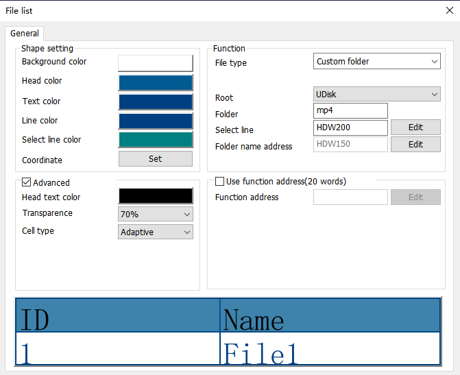
Configure the customized object as the above picture
Configure the file list object as below:
- Select the directory as the MP4 folder in USB flash disk. Set the file name address as HDW150
- Add the video controlling address, refer to the above video controlling address table.
- Compile the project and download it to HMI, trigger the bit address to play the video from the list.
Demo
PI8150ig Video Display: Download link
Wecon HMI can send email with information from fields to the specified email address as soon as the conditions is triggered, but email sending is based on the network.
Email setting
In "PIStudio" software, click "Project" → "E-mail" to open email function setting screen.

SMTP Settings
- Sender Name: Fill the sender's name, which is composed of Chinese characters, letters (case sensitive) and numbers. However, it cannot contain some special English characters such as spaces( ), commas(,), semicolons(;), double quotes("), or less-than signs(<). Maximum character length 32 is allowed.
- Password: Fill in the password or authorization code of the mailbox. If the server needs to set the authorization code, the authorization code needs to be used. If the authorization code is not used, the password is used. Please refer to the SMTP service in the mailbox for the authorization code information. It cases sensitive, maximum character length 32 allowed in password.
- Confirm Password: Confirm the password or authorization code of the mailbox.
- Email Address: Fill in the sender's email address, case sensitive, maximum character length 32 allowed in it.Such as support@we-con.com.cn.
- SMTP Server: Please refer to the mailbox account settings. If you enter a common mailbox, the corresponding server address will be automatically written. such as smtp.exmail.qq.com.
| Email server | Port number | |
|---|---|---|
| 163 email | smtp.163.com | 465 |
| 126 email | smtp.126.com | 465 |
| QQ email | smtp.qq.com | 465 |
| Sina email | smtp.sina.com | 465 |
| Sohu email | smtp.sohu.com | 465 |
| Yahoo email | smtp.mail.yahoo.com.cn | 465 |
| Google email | smtp.gmail.com | 465 |
- Encryption Type: SSL is a security protocol that provides security and data integrity for network communications. It encrypts network connections at the transport layer; TLS (STARTTLS) upgrades connections to SSL instead of using a separate encrypted communication port.
- The Port Number: Enter corresponding port number according to the SMTP serve addrress entered. You could only enter interger between 1 and 65535. Do not enter more than 6 digits in length. Common port numbers are port 25, 465 and 587.
- Port 25: It does not protect the original data when transmitting data. The data can be seen. Generally, port 25 must be selected as no encryption or TLS(STARTTLS) encryption mode to send data correctly.
- Port 465: It protect the original data when transmitting data. The data can not be seen. Generally, port 465 must be selected as SSL encryption mode to send data correctly.
- Port 587: The original data is protected only after the TLS(STARTTLS) command is executed. Generally, port 587 must be selected as TLS(STARTTLS) encryption mode to send data correctly.
- Error Message
- Set the error message receiving address, you could use the information to get the reasons of errors.
- The error types in the mail function are divided into two types: custom rule error and server's error.
- Custom rule errors are as follows.
| Message |
| Email settings are incorrect |
| Email account is incorrect |
| Email password could not include blank |
| the settings of SMTP server are incorrect |
| The range of SMTP server ports number should be integer, which is between 1 and 65535. |
| The type of encryption for SMTP is incorrect |
| The name of sender or email address setting is incorrect. |
| The names of Recipients or email address setting are incorrect. |
| The names of CC recipients or email address setting are incorrect. |
| The names of Secret delivery recipients or email address setting are incorrect. |
| Email topic could not be blank |
| Email content could not be blank |
| Total size of attachments should be below 25M |
| Attachment "xxxx" is nonexistent |
Server's errors are as follows.
| Message |
| smtp-server: 554 DT: SPM |
| smtp-server: 550 RP: TRC |
| smtp-server: 550 Limitation of connecting counts |
| smtp-server: 535 |
| smtp-server: 550 Error: Content rejected |
| smtp-server: 451 Internal server error |
| smtp-server: 535 Invalid login user or password |
| smtp-server: 550 too many sending requests today |
| smtp-server: 452 Too many recipients received this hour. |
| smtp-server: 535 Error: Authentication failed, system busy |
| could not connect: Connection timed out |
| Unexpected EOF on SMTP connection |
| could not initiate SSL/TLS connection |
| smtp-server: 530 Need to issue a STARTTLS command first. |
| could not resolve host |
| could not connect: Connection timed out |
| could not connect: Connection refused |
| smtp-server: 550 User not found: aaa.163.com |
- Manual Trigger
It is for modifying the email sending settings when HMI is running. According to the set manual trigger address, the address is offset backward to get the address of the corresponding function (a total of 201 words). Take HDW100 as an example.
| Address | Description |
| HDX100.0 | Sending trigger |
| HDX101.0~101.15 | It is used for triggering recipient groups, for example, HDW101.0 set ON, and the address in group 1 will be in recipient list. |
| HDX103.0~103.15 | It is used for triggering recipient groups, for example, HDW103.0 set ON, and the address in group 1 will be in CC list. |
| HDX105.0~105.15 | It is used for triggering recipient groups, for example, HDW105.0 set ON, and the address in group 1 will be in BCC list (Secret delivery). |
| HDW107~171 | The subject length is limited to 64 words. (If it exceeds, it will intercept 64 words of content); The length of 65 words only use 64 actually, the 65th word address is reserved; |
| HDW172~300 | The content length is limited to 128 words. (If it exceeds, it will intercept 128 words of content) |
| HDX301.0 | Whether to send an alarm record file as attachment (HMI V1.0 filename: AlarmDataFile.db) (HMI V2.0 filename: AlarmDataFile_0.db) |
- Emails that sent manually are not queued. Emails trigger by bit change, rising edge, falling edge and timing need to be sent in the sequence of triggering. The maximum value is 100, and those who are added after it is exceeded will be discarded. If an email is sending, it would send immediately after the current email is sent. If there is no email sending, it would send immediately.
- If the trigger condition sent manually is the rising edge trigger, before the mail is sent, no new mail will be sent even if it is triggered again. No matter the email is sent successfully or not, the corresponding trigger would be OFF.
- Emails that sent manually would only be sent once no matter the sending error is custom error, network or other errors.
Email sending settings

- Add. A maximum of 1024 email can be added.
- Modify. Select an email to modify the content and configuration.
- Delete. You could select an email to delete or click the "ID" column to delete in batch.

Email sending configuration.
- Theme. The value cannot be empty and case sensitive. The total length cannot exceed 256 characters.
- Content of email. The contents are divided into three combinations: text, alarm and variable. The list can contain only 32 items at most, and the total length of the preview cannot exceed 1024 items.
- Text. You could directly edit the text of language 1 to language 3. If you need to set multiple languages, click "edit all text" to set. You may also select "Text library". The content is case sensitive, and the total length of English/Chinese characters/numbers/symbols does not exceed 253.
- Alarm. You could select "bit alarm" or "word alarm" from the list. The content is from alarm text. if the alarm changes, the content changes with it. The content is case sensitive, and the total length of English/Chinese characters/numbers/symbols does not exceed 253.
- Variable. Set the corresponding variable address. Read value or strings according to the specified format, and the read information will be displayed in the corresponding position in the mail content.
- Preview. Combine the content of current edited email and diaplay it for you to modify the content conviniently. The preview length cannot exceed 1024.
- Sending method. It is divided into timed send interval and bit address trigger tranmission. The two methods cannot be used at the same time.
- timed send interval. After booting, the current system time is used to start calculating, and each time the time is up, the information will be sent to the set recipient in the form of an email, and the minimum time should be set to 5 minutes. Note: The first boot is not sent.
- Bit address trigger tranmission. When the set trigger address meets the trigger conditon, the information will be sent to the set recipient in the form of an email. If the content select alarm, the alarm address would be written in the trigger address. There are three methods to trigger: sending on rising edge, sending on falling edge and send when the bit changes.
- Recipient. It is set in groups. You could send multiple groups, and each group can have multiple recipients.
- Add CC. Sends the current email to other recipients.
- Add secret delivery. Sends the current email to other recipients, but the recipient and cc recipients do not see the BCC recipient.
- when sending an email, you must set a recipient. CC recipients and BCC recipients are not to be set. The total number of recipinet, CC recipients and BCC recipients is 40.
- Recipient priority. Set the priority order of recipients to recipient, BCC, and CC.
Recipient group setting

- All Group. The groups you added.
- Group to send. The groups that you send the emails to.
- Open recipinet settings. Set the information of recipients, and add and subtract groups.
Recipient setting

- Add. Add a recipient. There are non-dynamic recipient and dynamic recipient. They cannot be used at the same time. You may just fill in the recipient's name and email address. The dynamic recipient address is limited to 32 characters, and a maximum of 40 recipients can be added.

- Modify. Select one recipient and click "modify" or double click the recipient to modify. If it is non-dynamic recipient, you could modify the name and email address. The email is unique. If it is dynamic recipient, you could modify the address, and the address is unique.
- Delete. Select one recipient or multiple recipents to delete, or click the ID column to select all.
- Nuber of group. You could click the up/down arrow to increase or devrease groups. The default number is 1. The maximum number is 16.
- Description. To decribe the group information. The total length shall not exceed 32.
Test sending settings

| Error code | Cause of reason |
|---|---|
| 0 | CSMTP_NO_ERROR |
| 100 | WSA_STARTUP = Unable to initialize winsock2 |
| 101 | WSA_VER = Wrong version of the winsock2 |
| 102 | WSA_SEND = Function send() failed |
| 103 | WSA_RECV = Function recv() failed |
| 104 | WSA_CONNECT = Function connect failed |
| 105 | WSA_GETHOSTBY_NAME_ADDR = Unable to determine remote server |
| 106 | WSA_INVALID_SOCKET = Invalid winsock2 socket |
| 107 | WSA_HOSTNAME = Function hostname() failed |
| 108 | WSA_IOCTLSOCKET = Function ioctlsocket() failed |
| 109 | WSA_SELECT |
| 110 | BAD_IPV4_ADDR = Improper IPv4 address |
| 200 | UNDEF_MSG_HEADER = Undefined message header |
| 201 | UNDEF_MAIL_FROM = Undefined mail sender |
| 202 | UNDEF_SUBJECT = Undefined message subject |
| 203 | UNDEF_RECIPIENTS = Undefined recipient |
| 204 | UNDEF_RECIPIENT_MAIL = Undefined mail recipent |
| 205 | UNDEF_LOGIN = Undefined user login |
| 206 | UNDEF_PASSWORD = Undefined user password |
| 207 | BAD_LOGIN_PASSWORD = Invalid user login or password |
| 208 | BAD_DIGEST_RESPONSE = Server returned a bad digest MD5 response |
| 209 | BAD_SERVER_NAME = Unable to determine server name for digest MD5 response |
| 300 | COMMAND_MAIL_FROM = Server returned error after sending MAIL FROM |
| 301 | COMMAND_EHLO = Server returned error after sending EHLO |
| 302 | COMMAND_AUTH_PLAIN = Server returned error after sending AUTH PLAIN |
| 303 | COMMAND_AUTH_LOGIN = Server returned error after sending AUTH LOGIN |
| 304 | COMMAND_AUTH_CRAMMD5 = Server returned error after sending AUTH CRAM-MD5 |
| 305 | COMMAND_AUTH_DIGESTMD5 = Server returned error after sending AUTH DIGEST-MD5 |
| 306 | COMMAND_DIGESTMD5 = Server returned error after sending MD5 DIGEST |
| 307 | COMMAND_DATA = Server returned error after sending DATA |
| 308 | COMMAND_QUIT = Server returned error after sending QUIT |
| 309 | COMMAND_RCPT_TO = Server returned error after sending RCPT TO |
| 310 | MSG_BODY_ERROR = Error in message body (邮件正文中出现错误) |
| 400 | CONNECTION_CLOSED = Server has closed the connection |
| 401 | SERVER_NOT_READY = Server is not ready |
| 402 | SERVER_NOT_RESPONDING = Server not responding |
| 403 | SELECT_TIMEOUT |
| 404 | FILE_NOT_EXIST = File not exist |
| 405 | MSG_TOO_BIG = Message is too big |
| 406 | BAD_LOGIN_PASS = Bad login or password |
| 407 | UNDEF_XYZ_RESPONSE = Undefined xyz SMTP response |
| 408 | LACK_OF_MEMORY = Lack of memory |
| 409 | TIME_ERROR = time() error |
| 410 | RECVBUF_IS_EMPTY = RecvBuf is empty |
| 411 | SENDBUF_IS_EMPTY = SendBuf is empty |
| 412 | OUT_OF_MSG_RANGE = Specified line number is out of message size |
| 413 | COMMAND_EHLO_STARTTLS = Server returned error after sending STARTTLS |
| 414 | SSL_PROBLEM = SSL problem |
| 415 | SSL_PROBLEM = SSL problem |
| 416 | STARTTLS_NOT_SUPPORTED = The STARTTLS command is not supported by the server |
| 417 | LOGIN_NOT_SUPPORTED = AUTH LOGIN is not supported by the server |
Email status
Network disconnection error
If the fault is determined as a network disconnection error, the system does not delete the sent information and does not record the number of errors, and it would make an infinite send attempt.
Custom rule error
If the fault is determined as a custom rule error, delete the information.
Server return error
If the fault is determined as a server return error, then the error time add 1. It would try to send the email for 3 times. Regardless of whether the transmission is successful or not, it would delete the email to be sent. The test results are as follows.
| Server name | The number of sent | Consequences of exceeding the limit |
|---|---|---|
| 126 | 160 | No more delivery on that day |
| 163 | 160 | No more delivery on that day |
| we-con | 800 | No more delivery on that day |
| 50 | It can be sent again after a few minutes or a few hours | |
| sohu | 160 | No more delivery on that day |
| sina | 50 | It can be sent again after a few minutes or a few hours, but cannont be received normally |
| gmail | 500 | No more delivery on that day |
Message Prompt
- If the email to be sent is deleted, a message will pop up.
- If the email is sent successfully, a messge will pop up: "The email is sent successfully."
- If the five symbols ',' , ' | ', '<', '>' and '&' appear in the fields set by the message prompt, the message prompt will display an abnormal message.
Mail attachment
Currently, the email attachment function only supports sending the specified alarm record (AlarmDataFile.db file), and does not support selecting content to send.
USB keyboard
Introduction
- HMI support keyboard via USB port of HMI.
- When the keyboard function is enabled, the "Cursor Display" function is enabled by default. The user could move the cursor through the "up, down, left and right buttons" of the keyboard, and then press the Enter key to select the object.
- Multiple devices could be connected with HMI via USB HUB (up to 4 external devices), such as: mouse, keyboard, scanner, magnetic stripe reader, etc.
Enable function
In the software PIStudio, Click "Project" → "Project settings" → "Extend", and check "Enable keyboard" in "Input device" settings area as below.

Configuration decription
- When the keyboard function is enabled, the "Cursor Display" function is enabled by default. The user could move the cursor through the “up, down, left and right buttons” of the keyboard, and then press the Enter key to select the object;
- NumLock: When NumLock key is not lit, the keypad number is not allowed to be input (offline simulation does not allow all numeric keys to be input, including the numeric keys on the left side of the keyboard);
- Key combination: (1) "Shift" + the left side of the keyboard and the special symbol button, to achieve special character input, such as: ~ ! @ # $ % ^ & * ( ) _ + { } : "<> ? ;
- Use the system special addresses "HSW1073 and HSW1074" to write custom key combinations in the script (currently only two key combinations are supported);
- Caps Lock: In lowercase mode, shift+ letters, to enter uppercase; in uppercase mode, shift+ letters enter lowercase;
System special address
In practical application, the [Enable Keyboard] function could be combined with the related "system special address" to achieve multi-key combination operation.
| Address | Description | Function |
|---|---|---|
| HSW1073 | Keyboard key value | The currently pressed key value is displayed. The key value is shown in Table 1 (The Numeric/Character display object is not updated when it is being entered) |
| HSW1074 | Keyboard key status | Display current key states =0: key release =1: key press =2: Press and hold long (The Numeric/Character display object is not updated when it is being entered) |
| HSW1075 | Cursor speed | Control the movement speed of the cursor, the range is 0~100, the default is 20 |
| HSW1076 | X coordinate value of cursor | The X value of the current position of the cursor, range: 0~screen width-1 |
| HSW1077 | Y coordinate value of cursor | The Y value of the current position of the cursor, range: 0~screen height-1 |
| HSW1078 | The ASCII code of keyboard key | Only the ASCII values of letters, numbers, and symbols are displayed. The ASCII value of the function keys is not displayed, as shown in Table 2 (The Numeric/Character display object is not updated when it is being entered) |
| HSW1079 | Enable cursor position and Enter key mode | HSX1079.0 = 1: Set the cursor position according to HSW1076 and HSW1077 value; HSX1079.1 = 0: When Numeric/Character display object is entered, enter key is for end input instruction. When no Numeric/Character display object is entered, enter key is for normal click; HSX1079.1 = 1: Enter key only for normal click, not for keyboard end input instruction; |
Key-Value Appendix Table (Decimal) (104Keys)
| Key | Value | Key | Value | Key | Value |
|---|---|---|---|---|---|
| ESC | 1 | i I | 23 | Alt (Right) | 100 |
| F1 | 59 | o O | 24 | windows(Right) | 126 |
| F2 | 60 | p P | 25 | Menu | 127 |
| F3 | 61 | [ { | 26 | Right_ctrl | 97 |
| F4 | 62 | ] } | 27 | Print Screen | 99 |
| F5 | 63 | Enter | 28 | ScrollLock | 70 |
| F6 | 64 | CapsLock | 58 | PauseBreak | 119 |
| F7 | 65 | a A | 30 | Insert | 110 |
| F8 | 66 | s S | 31 | Home | 102 |
| F9 | 67 | d D | 32 | PageUp | 104 |
| F10 | 68 | f F | 33 | Delete | 111 |
| F11 | 87 | g G | 34 | End | 107 |
| F12 | 88 | h H | 35 | PageDown | 109 |
| ` ~ | 41 | j J | 36 | ↑ | 103 |
| 1 ! | 2 | k K | 37 | ↓ | 108 |
| 2 @ | 3 | l L | 38 | ← | 105 |
| 3 # | 4 | ; : | 39 | → | 106 |
| 4 $ | 5 | ' " | 40 | NumLock (Keypad) | 69 |
| 5% | 6 | \ | | 43 | / (Keypad) | 98 |
| 6 ^ | 7 | Shift (Left) | 42 | * (Keypad) | 55 |
| 7 & | 8 | z Z | 44 | - (Keypad) | 74 |
| 8 * | 9 | x X | 45 | + (Keypad) | 78 |
| 9 ( | 10 | c C | 46 | Enter (Keypad) | 96 |
| 0 ) | 11 | v V | 47 | . (Keypad) | 83 |
| - _ | 12 | b B | 48 | 0 (Keypad) | 82 |
| + = | 13 | n N | 49 | 1 (Keypad) | 79 |
| Backspace | 14 | m M | 50 | 2 (Keypad) | 80 |
| Tab | 15 | , < | 51 | 3 (Keypad) | 81 |
| q Q | 16 | . > | 52 | 4 (Keypad) | 75 |
| w W | 17 | / ? | 53 | 5 (Keypad) | 76 |
| e E | 18 | Shift (Right) | 54 | 6 (Keypad) | 77 |
| r R | 19 | Ctrl (Left) | 29 | 7 (Keypad) | 71 |
| t T | 20 | Windows(Left) | 125 | 8 (Keypad) | 72 |
| Y y | 21 | Alt (Left) | 56 | 9 (Keypad) | 73 |
| u U | 22 | space | 57 |
ASCII Code
| Code | Value | Code | Value | Code | Value | Code | Value |
| 32 | space | 56 | 8 | 80 | P | 104 | h |
| 33 | ! | 57 | 9 | 81 | Q | 105 | i |
| 34 | " | 58 | : | 82 | R | 106 | j |
| 35 | # | 59 | ; | 83 | S | 107 | k |
| 36 | $ | 60 | < | 84 | T | 108 | l |
| 37 | % | 61 | 85 | U | 109 | m | |
| 38 | & | 62 | > | 86 | V | 110 | n |
| 39 | ' | 63 | ? | 87 | W | 111 | o |
| 40 | ( | 64 | @ | 88 | X | 112 | p |
| 41 | ) | 65 | A | 89 | Y | 113 | q |
| 42 | * | 66 | B | 90 | Z | 114 | r |
| 43 | + | 67 | C | 91 | [ | 115 | s |
| 44 | , | 68 | D | 92 | \ | 116 | t |
| 45 | - | 69 | E | 93 | ] | 117 | u |
| 46 | . | 70 | F | 94 | ^ | 118 | v |
| 47 | / | 71 | G | 95 | _ | 119 | w |
| 48 | 0 | 72 | H | 96 | ` | 120 | x |
| 49 | 1 | 73 | I | 97 | a | 121 | y |
| 50 | 2 | 74 | J | 98 | b | 122 | z |
| 51 | 3 | 75 | K | 99 | c | 123 | { |
| 52 | 4 | 76 | L | 100 | d | 124 | | |
| 53 | 5 | 77 | M | 101 | e | 125 | } |
| 54 | 6 | 78 | N | 102 | f | 126 | ~ |
| 55 | 7 | 79 | O | 103 | g |
Scripts example
'HSW1073 key value
'HSW1074 key states
- 0: released;
- 1: pressed;
- 2: Holding pressed
'HSW1078 ASCII value of key
Example 1
if @W_HSW1074 = 1 or @W_HSW1074 = 2 'Press Ctrl key
@W_HDW1000 = 1
else 'Release Ctrl key
@W_HDW1000 = 0
endif
endif
Example 2
if @W_HDW1000 = 1 then 'Combination Ctrl + F1
@W_HDW2000 = @W_HDW2000 + 1 'Function of combination key is HDW2000 + 1
endif
endif
Example 3
if @W_HDW1000 = 1 then 'Combination Ctrl + F2
@W_HDW2000 = @W_HDW2000 - 1 'Function of combination key is HDW2000 - 1
endif
endif
Example 4
if @W_HSW13 > 0 then
@W_HSW13 = @W_HSW13 - 1
endif
endif
Example 5
@W_HSW13 = @W_HSW13 + 1
if @W_HSW13 > 3 then
@W_HSW13 = 3
endif
endif
Camera
Wecon has a variety of HMIs that support IP cameras and EZVIZ cameras, and the displays differ between different models;
| IP camera | PI3000ig | PI8000ig |
|---|---|---|
| HMI display | X | ✔ |
| LAN monitoring | X | X |
V-NET remote screen | X | X |
| Cloud SCADA | X | X |
| EZVIZ camera(China server) | PI3000ig | PI8000ig |
|---|---|---|
| HMI display | X | ✔ |
V-NET remote screen | ✔ | ✔ |
| Cloud SCADA | ✔ only -C model | ✔ |
| LAN monitoring | ✔ | ✔ |
| EZVIZ camera(Other server) | PI3000ig | PI8000ig |
|---|---|---|
| HMI display | X | ✔ |
V-NET remote screen | X | X |
| Cloud SCADA | ✔ only -C model | ✔ |
| LAN monitoring | X | X |
IP camera
Introduction
- An external IP Camera (web camera) can be used to display the screen captured by the it to achieve real-time monitoring of the scene of the equipment.
- ONVIF protocol and H.264 coding camera (RTSP web camera) are supported.
Recommended Models:
- Hikvision
- DS-2CD1321D-I
- DS-2CD3T20FD-I3W
- DS-2CD1221D-I3
- DS-2CV3Q21FD-IW
- Dahua
- DH-IPC-HFW1025D
- DH-IPC-HFW1235M-I1
IP Camera Parameters Comparison for HMI Series
| HMI Series | System Version | Support IP Camera or Not | Number of Cameras |
|---|---|---|---|
| PI8000 | HMI V1.0/V2.0 | Yes | 1 |
| PI9000 | HMI V1.0/V2.0 | Yes | 4 |
| PI3000ig | HMI V2.0 | No | N/A |
| PI8000ig | HMI V2.0 | Yes | 4 |
Camera search
In the software PIStudio, Click "Project" -> "Project settings"-> "Extend", and check "Enable camera search module", shown as below.

The maximum number of searches: Configure the number of online camera. The maximum number of searches does not exceed 20, and should be greater than that of online camera.
Function address
To configure the information of searches anf the records of search results. There are as follows.
| Address | Description | Length |
| HDW200 | Username | 20 words |
| HDW220 | Password | 20 words |
| HDX240.0 | Falling edge trigger search | 1 bit |
| HDX240.1 | Search status 0: The search is complete. 1: It is searching. | 1 bit |
| The first search result | 80 words | |
| HDW241 | IP address | 16 words |
| HDW257 | =1: correct password =0: wrong password | 1 word |
| HDW258 | Device serial number | 43 words |
| HDW301 | Camera alias | 20 words |
| The second search result | 80 words | |
| HDW321 | IP address | 16 words |
| ... | ... | ... |
The username and password of function address need to entered manually. When searching for cameras, the username and password will be matched first, then each camera under the account will be retrieved, and the retrieved results will be stored in the response address. If the password is correct, the corresponding serial number would be displayed.
Camera display
Add the object "camera display" to the project, click "Enable rtsp camera", as below.

Compile and download project, please click [Search Camera] button to get camera information in LAN The username and password here need to be entered manually. During searching camera, it will try to use this username and password to log in IP camera and store the result of login. If the password is correct, the “password correct” address will be displayed as 1 and the device serial number will be displayed. If the “password correct” address is 0, the device serial number would not be displayed.
Function address
| Address | Description | Length | |
|---|---|---|---|
| HAW100 | Username | 20 words | |
| HAW120 | password | 20 words | |
| HAW140 | Alias | 20 words | |
| HAW160 | Device serial number | 43 words | |
| HAW203 | Camera ID | 1 word | |
| HAW204 | Camera Control | 1 word | |
| HAX204.0 | Open camera | 1 word | |
| HAX204.1 | Close camera | 1 word | |
| HAX204.2 | Camera up | 1 word | |
| HAX204.3 | Camera down | 1 word | |
| HAX204.4 | Camera left | 1 word | |
| HAX204.5 | Camera right | 1 word | |
| HAX204.6 | screenshot | 1 word | |
| HAX204.7 | Binding camera | 1 word | |
| HAX204.8 | Set Alias | 1 word | |
| HAX204.9 | Camera stop moving | 1 word | |
| HAW205 | Camera status =0: camera disconnected =1: camera connected =2: Camera is connecting | 1 word | |
| HAW206 | Screenshot save location =0: Screenshot is saved into flash =1: Screenshot is saved into USB disk =2: Screenshot is saved into SD card | 1 word | |
Operating Procedures
Fill the camera ID address with the camera serial number searched by the camera search module, and trigger the binding address to fill username and password.
- If the camera searching is disabled, then users need to manually enter the information of this camera, including username, password, and device serial number. Device serial number could be obtained by checking the label of camera.

- If the IP CAMERA was triggered successfully, we could see the monitor screen and we could also set a alias for the camera and control the movement of the camera(up, down, left and right, some IP camera could not support the movement) or the screenshot. These operations could not be performed if camera off.

✎Note:
- Camera configuration. When you get the camera, you need to activate the camera and enable the onvif protocol for the camera according to the user manual and tools provided by the camera manufacturer. If the configuration is not correct, the camera cannot be used on the HMI.
- When reading camera information, you need to configure the user name and password for the camera. When multiple cameras are enabled, you are advised to set the user names and passwords of all cameras to be the same.
- When using the camera function, ensure that the camera and HMI are on the same LAN. When the HMI is directly connected to the camera through a network cable, set both HMI and camera to static IP addresses as follows.
| HMI | Camera | |
|---|---|---|
| IP address | 192.168.1.1 | 192.168.1.2 |
| Gateway | 192.168.1.1 | 192.168.1.1 |
- You could obtain the camera from the "Camera Search module" in "Project parameters" or manually fill in the address. You can obtain resources for the camera display object in the Camera Search module or manually enter the parameters.
- You are advised to configure and confirm the user name and password of the camera before using it. Do not use the wrong user name (password) to search for or link to the camera. Once the wrong user name (password) is exceeded for a certain number of times, the camera will be locked. During the lock period, the camera will reject any connection for at least half an hour generally.
- When monitoring HMI cameras, do not monitor the same camera at the same time. Otherwise, the monitoring screen may be lost.
- When the camera is disconnected due to network reasons, the system wouyld try to reconnect the camera every 20 seconds.
- The alias of the camera is saved in the user database. The alias in old project is retained when downloading new project, if [user database] is selected. Otherwise the it will be deleted.

Demo download link
https://drive.google.com/open?id=10UR1cg8KDjcTvKJYgk1KR8z4YIApIsD8
Camera setting
1.After getting a new camera, we must first follow the documentation and tools provided by the camera manufacturer to activate the camera and turn on the camera's onvif protocol, otherwise it cannot be used in our screen.
2.It is best to confirm the username and password before use. Do not keep searching or connecting to the camera with the wrong username and password. After a certain number of incorrect attempts, the camera will lock the device and refuse any connection during the lock period.
3.Enable the open network video interface.

4.The camera component of the HMI can only access the sub-stream of the camera. Due to system limitations, it is recommended that the sub-stream refer to the following configuration.
| Video Type | Video stream |
|---|---|
| Frame rate | 8 ~ 12 |
| Video Encoding | H.264 |
| Image Quality | Low |
FAQ
Why my HMI can not search the camera?
LAN Monitoring
WECON provides [HMI Monitor System] software for user to monitor PI3000 series HMI in Local area network (LAN).
This function is only for the model with -O. For example PI3070N-O.
[HMI Monitor System] software
Device List: It displays HMIs, that connected into this monitor software;
State Indicator: It shows state of HMI, green means online, gray means offline;
Operation Buttons: It provides three operations for HMI device;
- Add: Click it to open add setting window;
- Delete: Click it to delete selected HMI device;
- Monitor: Click it to open monitor window for selected HMI device;

Operating procedures
Click [Add] button to open setting window;
Enter HMI IP and Note;
Click [Connection test] button;
- If IP is correct, it will display tip as below;

- If IP is incorrect, it will display tip as below

✎Note: For using this function in PC, it requires the setup of LAN Monitoring Firewall, using Windows 7 system as example. If this function works well in your PC, please ignore below content.
Solution 1: Disable Firmware Completely
Open "Control Panel" and select "System Security".

Select "Windows Firewall"

Select "turn Windows Firewall on or off"

Select "Turn off Windows Firewall"

Solution 2: Do not close the firewall, but allow HMIUI to pass through the firewall
Open Control Panel selection "system Security"

Select "Windows Firewall"

Select "run a program or function through Windows Firewall"

Select "Allow to run another program".

Select "browse" in the pop-up dialog box.

Locate the HMIUI.exe file in the HMIUI directory under the installation path of the monitoring software, and double-click HMIUI.exe.

Select "add".

Check the corresponding options.

select "OK".

Remote access config
Introduction
In the traditional concept, it is rather Difficult and complicated to remotely connect HMI via Ethernet. Users not only need to consider the security issue, but also need to set up complex network parameters. In addition, subject to the stage of the network environment, users have to do everything possible to think of ways through all levels of routers and switches. And an independent IP could only correspond to one HMI in tradition sense of the remote control. The WECON remote access system will solve all of those problems.
The solution of WECON HMI remote access is "Everything is possible with one network, one HMI, one cable". No matter where the HMI is, users could easily remote access HMI through the network, to achieve exclude exceptions and resolve them in the first time. In local area network or remote Internet, users could make HMI connect to Ethernet by one cable without setting any parameters. All network settings could be set by WECON remote access system.
Set the IP of HMI

Use mobile phones, computers, tablets, etc., open a browser, enter the IP, you could access the project in the HMI screen.
- You are advised to use Chrome or Firefox. If you want to use Internet Explorer, use Internet Explorer 9 or later.
- 360, Sogou and other browsers need to use speed mode.
- Support the iphone's own browser, or install a latest UC browser.
- As long as the browser supports HTML5.
Access through the cloud
Access through the cloud platform, enter the machine code (the machine code of each HMI is independent) and model, then monitor the HMI remotely.
Access through V-NET (ig series)
Access through the V-NET, enter the machine code (the machine code of each HMI is independent) and the device password, bind the HMI, and monitor the HMI remotely.
System Components
WECON PI8000 and advanced HMI with [-R], such as PI8070-R;
WECON Smart APP or WECON Cloud platform
User manual for WECON Smart and cloud platform download link
https://drive.google.com/open?id=1hI8QI4vmJhAis2GFuCISChV9xGU0BxQ9
FAQ
- What is the difference between the-R model and the normal model?
- The-R model can be accessed directly and unrestricted. Normal models need to buy cloudmonitoring products before access. The number of monitoring normal model is limitedaccording to the customer's purchase of cloud monitor packages.
- How many customers could remote access HMI at the same time?
- It supports max. 4 customers access HMI in the same time.
Mulit-link(For HMI V1.0)
Introduction
The main principle of Multi-link is to use the method of Master&Slave to implement the One machine-Multiple screens by ethernet port. For example, one Master HMI connect to one Slave HMI, the Slave one can write or read value from PLC which is communicated with Master.
In Multi-link, there is only one Master, and all the other HMIs are Slaves. The Master HMI is the only one device communicate with PLC, and the data received from the PLC is transmitted to each slave through the host HMI(Master).

At present, the Multi-link is regarded as special function. So not any model HMI support it. Need the HMI come with the special machine code. The series support Multi-link function right now: General, HMI+, i Series. Multi link doesn’t support the online simulaion. PI3000/PI3000+/PI3000i series can only have one Slave when using this function, while PI8000/9000,PI8000+/PI9000+ series can use at most 5 Slaves.
PIStudio settings
Check to enable Multi-link, select the corresponding option. For example, if it is a slave HMI, select Slave.

Master IP address setting: Click "Project"→"Project settings"→"HMI IP", as below.

Slave project
In order to let the fonts in the Slave and the Master consistent with each others, so Slave project needs to add one screen that can set the IP address of Master HMI for connecting to the Master, on the original the Master project. If Master project has components that use other font styles, and Slave project If there is no component corresponding to Master project, then the default font style SimSun would be displayed when the Multi-link is enabled. To avoid the Slave device prompts communication timeout message, you can add HSW9 = 1 in the initial script of Slave device.
Address
| Address | Address Description | Usage Method |
| HSW1100 | The IP of Master HMI | IP address high endian 1 |
| HSW1101 | IP address high endian 2 | |
| HSW1102 | IP address high endian 3 | |
| HSW1103 | IP address high endian 4 | |
| HSW1104 | Control the Slave to connect to the Master or not | 1: Connect to Master 0: Disconnect |
Notice
During the connection, if the Master is downloading program, there is a highly chances that the slave screen is abnormal, and the Gallery and imported pictures cannot be displayed.
After the download process of Master HMI is finished, Slave needs to be restarted to monitor normally.
- If the Master and Slave are operated on any screen, the screen also will follow the changes and synchronize for other side.
- Using HSW12 = 1 on the Master, which can not affect each other.
- There is no momentary delay function for buttons.
- Multi-link version bit switch has no Min. holding time.
- PI3000 series can only have one Slave when using this function, while PI8000/9000 series can use this function at most 5 Slaves.
- Only supports Multi-link connection in the LAN network (local area network), or direct connection between Master and Slave.
- The Master and Slave projects must be consistent (mainly for keeping the font style used by the Master and Slave HMI consistent), and the Slave HMI always adds the configuration of the “Master IP address".
- After the special address is enabled, Slave will remotely monitor the interfaces from Master, and the source project will not be executed.
✎Note: Slave project only needs to ensure that there is "the HSW address of the Master HMI IP" and the font style used by the Master.
Mulit-link(For HMI V9.0)
Introduction
- Multi-link function is through the master-slave mode of communication, using Ethernet cable connection to realize one machine with multiple screens, that is, one HMI connects another HMI through the Ethernet port, and reads or writes the data of the PLC connected by the master.
- In the multi-link operation, one HMI is the master (Master), and the other is the slave (Slave). Master HMI is the only one that communicates with the PLC, and the data receiving from the PLC is transmitted to each slave through the master (Master).
Supported Series
ig series
3000ig support 10 slaves
8000ig support 64 slaves
Step of connecting slave to master
Go backstage,and Click[Cloud]

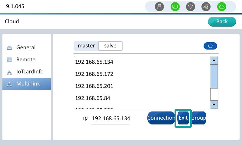
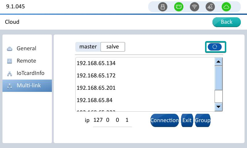
Click multi-link to enter the interface,Click Slave or Master (Select Slave to use the device as slave, select Master to use the device as master).And Find the device list, the master device that you need to connect to, and click the master device corresponding to IP.
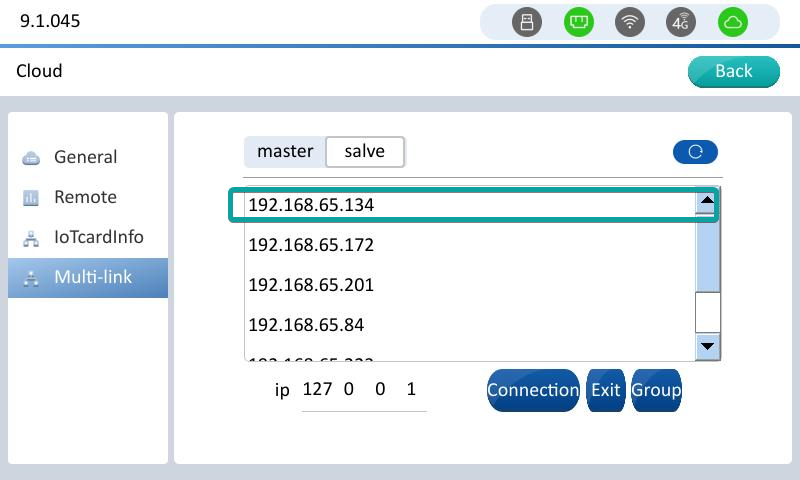
After clicking the master device of the corresponding IP, the IP of the master device is automatically filled in to the checkbox below, and click [Connection] to connect to the master as a slave.
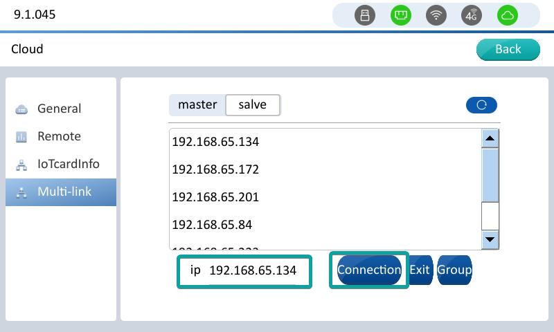
After the connection is successful and the device restarts, it enters the display interface to the master, indicating that the connection is successful.
Use and Instructions of Button Functions
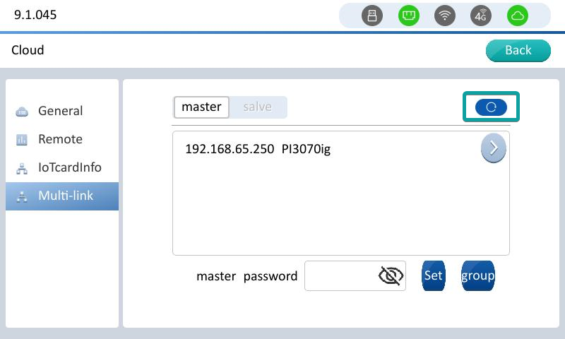
From the machine device to the multi-machine interconnection configuration interface, the Master button is not clickable, and the IP list of the master device that can be connected is displayed.
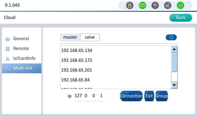
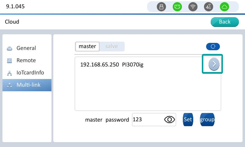
Master device Enter the multi-machine interconnection interface, click the master button, you can see the IP list of the connected slave devices.
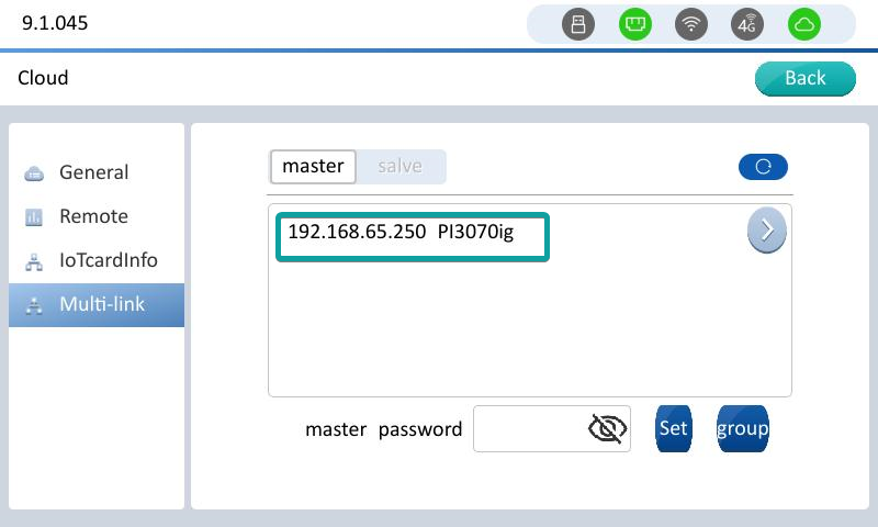
Slave equipment Click the exit button of the multi-machine interconnection interface to exit the connection status.Device restarts, slave exits.
Master multi-machine interconnection interface. Click the right-arrow to view the information of the corresponding device of the slave.
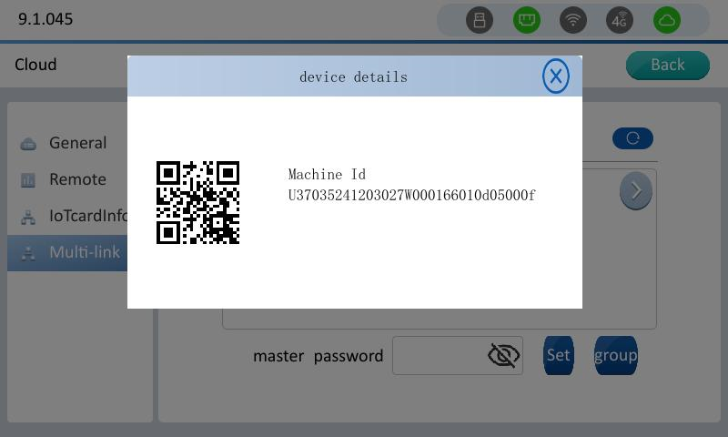
Device information
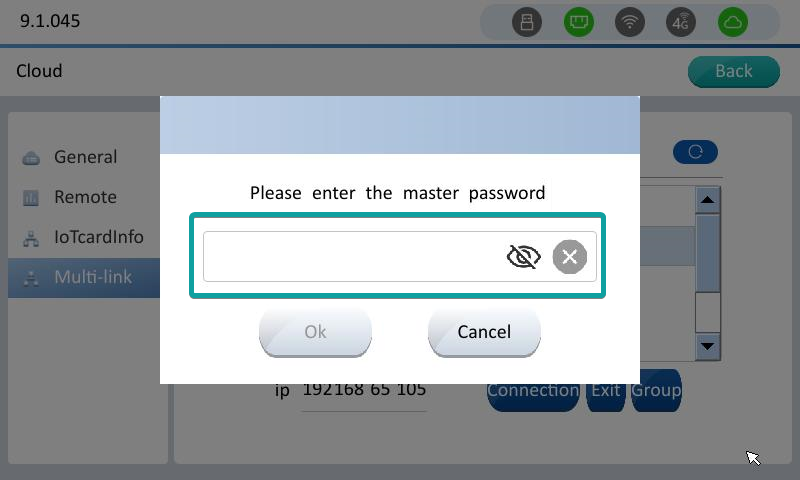
Set multi-computer interconnection master password, enter the password, click Settings to set the password. A password is required for the slave to reconnect to this master. Cancel the password, clear the password box directly, and click Settings.
Master device

Slave device
Click the refresh button on the master or slave interface to refresh the new access device, or find the master device.
Slave device
Master device
Grouping function
The grouping function is to group according to different screens: the same group currently displays the same screen (synchronous), different groups currently display different screens (asynchronous), and different groups can be configured with different initial screen numbers.
If the slave is not configured with any group, then the screen of this slave is synchronized with the master (the master switches the screen, and the slave also switches the screen). If the group is configured separately, the screen of the slave is asynchronous (the master switches the screen, bue the slave does not switch the screen).
For example:
Group 1: scr1, you can configure the initial screen number 1
Group 2: scr2, you can configure the initial screen number 2
If a slave in scr1 (192.168.65.10) switches the screen, all slaves in the group will jump to the current screen (192.168.65.10). The screens of scr2 and the master remain unchanged. Similarly, the effect of switching the screen of a slave in scr2 is the same as that of scr1.
For slaves that are not configured with a group, the screen follows the master.
1. The slave connects to the master
2. On the master interface, click “Group”


3. Enter the group name.

4. Enter the scree number. (The screen number you set is the screen number that is initially displayed when the slave is powered on.)

5. Add new group successfully

6. Add the slave to the corresponding group

7. Add successfully

V-NET Access (PC Side)
Login interface
Enter the platform, as shown in Figure 1:
New users need to register first.
- The successfully registered account is the administrator account, which can bind the device and other operations.
- The user needs to remember the registered account and password, and able to log in simultaneously on the PC Client/APP.
- If the user forgets the password, he can click "Forgot Password" to reconfigure the password.

Figure 1
Enter the account and password, and then click the "Login" button.
After successfully logging in, enter the "V-NET" interface, as shown in Figure 2. Add the HMI information you want to access through the "+" in the lower left corner.

Figure 2
After the Add Device window pops up, enter the machine code and password of the device to add the device, as shown in Figure 3:

Figure 3
- Device machine code: Each HMI has a unique and independent machine code, which is used to identify every remote device. (When binding multiple devices at the same time, the device passwords must be the same. Only one machine code can be entered on one line. When entering multiple machine codes, use the "Enter" key to change the line. If the format is wrong, the binding operation will fail and error will occur). Method of obtain machine code:
- PIStudio → "Project" → "Tool"→ "Download" →Copy the machine code.
- Long press the upper right corner of HMI to enter the backstage, you can see "Machine Id" in "Machine Info".
- Obtain the machine code from the backlabel of the device.
- Device password: Refers to the Cloud access password, the default is 6 digits 8 (888888). Please refer to the cloud configuration if you first time binding the device.
- The length is 6 digits, English and special characters in English are allowed, spaces are not allowed, and cannot be empty.
- Device alias: Refers to the name recognition of device in the menu bar of V-NET.
- Maximum 12 digits, except ·_-+=}]",.?,;: ""”【】—()...! these Special characters allowed others are limited to input, no spaces or blanks are allowed.
- If the device is successfully bound, click OK, and it would prompt message: The device is bound successfully!
V-NET module
Remote Monitoring
The remote monitoring module can display the project page of the current screen in real time, and can operate the project on the web page, and the control of the screen. As shown in Figure 4:

Figure 4
Data Viewing
The data viewing module is divided into Communication port, Collection point, Alarm configuration, Alarm records, Data Record configuration , Data Record, etc. As shown in Figure 5:

Figure 5
The parameter configuration is as follows:
- Communication port : The communication port information, includes connection method and protocol name, can only be viewed, and cannot be added or modified. This info comes from the settings from HMI.
- Collect point:Data monitoring module of the device. The collection point is the monitoring data, and its read-write, write-only, and read-only permissions also come from the Tags settings from HMI.
- Note: You cannot add or delete collection points here. The read & write permissions of the collection points in the HMI will directly restrict the modification of the read & write permissions of the collection points by V-NET.
- Alarm configuration: Alarm records of the device, monitoring points cannot be added, confirming the Alarm record and exporting data can be performed.
- Data Record configuration: Data Record is historical data of the device, monitoring points cannot be added, curve and list viewing method are supported, and data records can be exported.
Remote Download
This function allows application on the PC to download directly to PLC or HMI, as shown in Figure 6:

Figure 6
PLC download (only for Pass-through)
- Click the setting (gear icon) in the upper right corner of PC Client, and a dialog will pop up. The red area is the COM port configuration when the PLC pass-through downloads. As shown in Figure 7:

Figure 7
- After configuring the COM port, go to the remote downloaded, PLC download, to config the name, communication port, virtual serial port and other configurations as shown in Figure 6.
HMI Download (only for Pass-through)
- Click the setting (gear icon) button in the upper right corner of PC Client, and a dialog will pop up. The red area is the configuration of the HMI download tool. As shown in Figure 8:

Figure 8
- Click the setting (gear icon) button, a dialog box will pop up, and automatically detect and find the PIStudio that has been installed in PC and conforms to the version, as shown in Figure 9:
- Location: Display the installation path of the current PIStudio.
- Version: Corresponding to the version of the current PIStudio.
- Browse: Click to manually set the installation path of PIStudio.

Figure 9
Basic
In the "Basic" sub-page of Basic, HMI name, record reserved selection, password, location and remarks, etc. As shown in Figure 10:
 Figure 10
The device name is an alias of HMI, which is mainly used for easy distinction.
Online status: You can click the refresh button to refresh the online status of the HMI.
Machine code: Each HMI has a unique and independent machine code.
Record reserved: Checking the corresponding options will let HMI to suspend updating the corresponding configuration after downloading a new project.
Password: Refers to the cloud access password, the default is 6 digits 8 (888888); the cloud access password can be set and modified, the specific location is:
- V-NET → specified HMI → Baisc → "password” → modify and save, as shown in Figure 10.
- "Project" → "Cloud" → "Basic" → "Password" → of PIStudio (only unbind HMI can be modified), see Cloud Configuration.
Maximum storage of Alarm data: The maximum number of alarm data saved, with a range of 1 to 50000.
Positioning:
- Use the device base station positioning to locate.
- Use manual positioning.
RE Series Instructions
The RE series could easily meet advanced requirements such as real-time dashboard in industrial site.
Operation Steps
(1) New project
1) Click [New Project];
2) Name the project;
3) Select [HMI Series] as [RE Series];
4) Select [HMI Model] as [V-BOX RE-00/V-BOX RE-4G] (according to the actual needs);
5) Optional Step: Select the resolution. (Due to the RE V-Box doesn't have the actual display, so it can select various resolutions)
6) Optional Step: Same to the ig series, user could select the Screen style for RE series products;
7) Click [OK] to finish the creation;

8) Establish the communication protocol setup;

(2) Enable Cloud
Enable the Cloud function to let the RE V-Box able to access the V-NET platform.
1) Click [Cloud];
2) Click [Enable];
3) Select the corresponding server;
4) Click [OK] to finish the settings;

(3) Project Download
After project is done, user can compile and download the project into device. Same to the HMI, there are two download methods available for RE series, one is micro USB cable and the other one is the Ethernet.
1) Click [Compile];
2) Click [Download] to pop up the download tool;
3) Select the download port;
4) Click [PC to HMI];
5) Click OK to reboot the device;

(4) V-NET Platform Bind and browse
About this part, please back to the heading V-NET Access on the beginning or check the corresponding video: The ig V-NET Access(The general steps are same).
1) Remote monitoring
The remote monitoring module can display the project screen of the current HMI in real time and can operate the project on the web page.

2) Data view
It is divided into Communication port, Collection point, Alarm configuration, Alarm Recird, Data Record configuration, Data Record etc.
About this part, please go to the Data Tool to check the details, or check the corresponding video: The ig Upload to Cloud Configuration

3) Pass-through
The pass-through function allows application files on the PC to maintenance the project program on site through RE devices.
About this part, please go to the Device Pass-through chapter to check the details,
✎Note:
- The pass-through function is unavailable on the browser web page, user need to change to V-NET Client to process the procedures;
- When the device is offline, button [Start Pass-through] cannot be clicked;
- When the device firmware is too low, button [Start Pass-through] cannot be clicked;
- Current user doesn't have permission for pass-through device or the device is shared by others, button [Start Pass-through] cannot be clicked;
- When the current user already has one device that is being penetrated, button [Start Pass-through] button cannot be clicked;
4) LAN Monitoring
Open the browser and enter the IP of the RE V-Box. Just like the following screenshot:


