Siemens
Siemens
S7-200 Smart Ethernet
Supported Series: Siemens S7-200 SMART Series Ethernet Module.
Website: http://www.siemens.com/entry/cc/en/
HMI Setting
| Items | Settings | Note |
| Protocol | Simens S7-200 Smart Ethernet | |
| Connection | Ethernet | |
| Port No. | 102 | |
| PLC station No. | 2 |
Address List
| Type | Device register | Format | Range | Note |
| Bit | I | I ddddd.o | 0.0~99999.7 | |
| Q | Q ddddd.o | 0.0~99999.7 | ||
| V | VWbit ddddd.o | 0.0~99999.7 | HMI register:VWbit | |
| V | V ddddd.o | 0.0~99999.7 | HMI register:V | |
| M | M ddddd.o | 0.0~99999.7 | ||
| SM | ddddd.o | 0.0~99999.7 | ||
| S | ddddd.o | 0.0~99999.7 | Read only | |
| T | ddddd | 0~99999 | Timer state, read only | |
| C | ddddd | 0~99999 | Counter state, read only | |
| Word | I | IW ddddd | 0~99999 | HMI register:IW |
| IB ddddd | 0~99999 | HMI register:IB | ||
| Q | QW ddddd | 0~99999 | HMI register:QW | |
| QB ddddd | 0~99999 | HMI register:QB | ||
| AI | AIW ddddd | 0~99999 | HMI register:AIW | |
| AIB ddddd | 0~99999 | HMI register:AIB | ||
| AQ | AQW ddddd | 0~99999 | HMI register:AQW | |
| AQB ddddd | 0~99999 | HMI register:AQB | ||
| V | VW ddddd | 0~99998 | HMI register:VW VW0=VB (0~1) VW2=VB (2~3) Address value is a multiple of 2 | |
| VD ddddd | 0~99996 | HMI register:VD VD0=VB (0~3) VD2=VB (4~7) Address value is a multiple of 4 | ||
| VB ddddd | 0~99998 | HMI register:VB | ||
| M | MW ddddd | 0~30 | HMI register:MW MW0=MB(0~1) MW2=MB(2~3) Address value is a multiple of 2 | |
| MD ddddd | 0~99999 | HMI register:MD MD0=MB(0~3) MD4=MB(4~7) Address value is a multiple of 4
| ||
| MD dd | 0~31 | HMI register:MB | ||
| T | TW ddddd | 0~99999 | HMI register:MW Value of timer | |
| C | CW ddddd | 0~99999 | HMI register:CW Value of counter | |
| S | SW ddddd | 0~99999 | HMI register:SW | |
| SB ddddd | 0~99999 | HMI register:SB |
Communication Settings
Set PLC IP in [Device IP] settings;

- PLC IP Address: PLC IP
- PLC pot No.: 102(fixed)
- Network:TCP_Client_2N(fixed)

- Wait timeout: depend on actual network situation (more than 1500 ms)
PLC Setting:
①Open STEP 7-MicroWIN SMART, create a new PLC project or open the project that has been created.
Create new project:Double click[CPU SR20]→[System Block]→[Module] CPU SR20(AC/DC/Relay)→[OK].
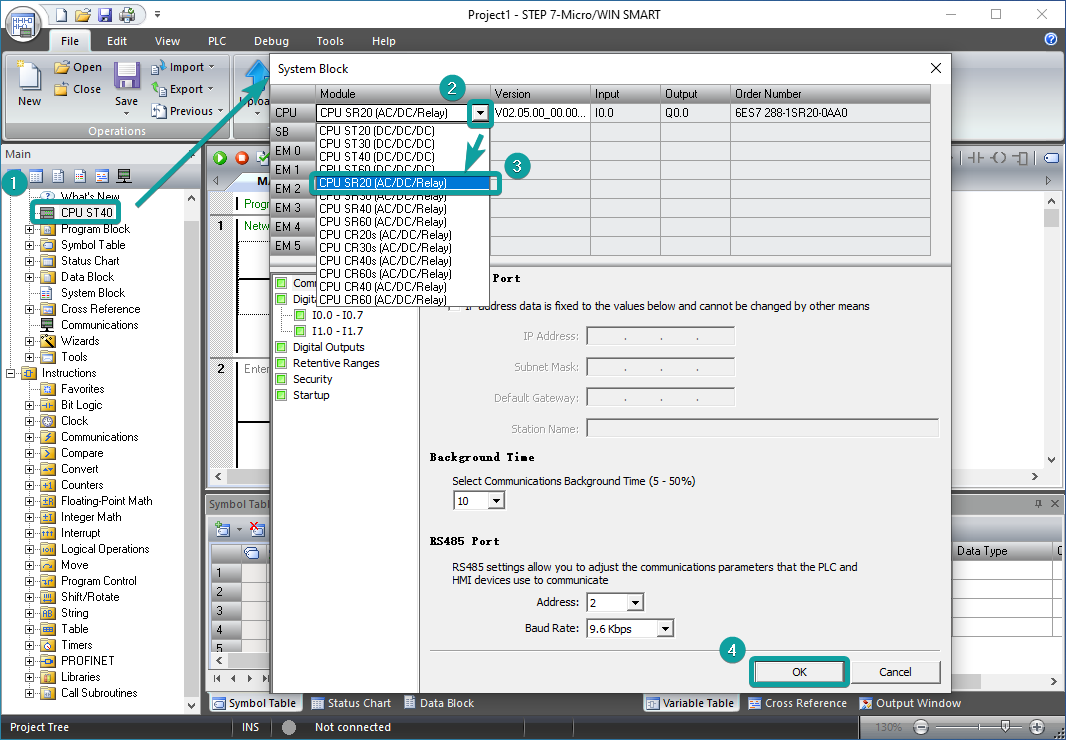
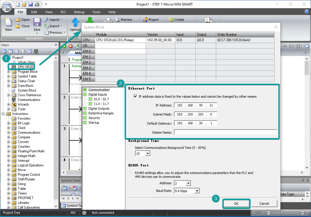
②PLC Default Parameters: Double click[CPU SR20]→[System Block]→[Ethernet Port]→[IP Address]192.168.39.21[Subnet Mask]255.255.255.0[Default Gateway]192.168.39.1→[OK]
Cable Wiring

S7-300 Ethernet
Supported Series: Siemens S7-300 series PLC
HMI Setting
| Items | Settings | Note |
| Protocol | Simens S7-300 Ethernet | |
| Connection | Ethernet | |
| Port No. | 102 | |
| PLC station No. | 2 | Need to be same as the PLC setting |
Address List
| Type | Device register | HMI register | Format | Range | Note |
| Bit | I | I | I ddddd.o | 0.0~99999.7 | |
| Q | Q | Q ddddd.o | 0.0~99999.7 | ||
| M | M | M ddddd.o | 0.0~99999.7 | ||
| DB0.DB~DB9999.DB | DBxDBD | DBxDB nnnndddd.o | 0.0~99999999.7 | nnnn: block number; dddd: address; | |
| Word | I | IW | IW ddddd | 0~99999 | |
| Q | QW | QW ddddd | 0~99999 | ||
| M | MB | MB ddddd | 0~99999 | ||
| MW | MW ddddd | 0~99999 | MW0=MB(0~1) MW2=MB(2~3) Address value is a multiple of 2 | ||
| MD | MD ddddd | 0~99999 | MD0=MB(0~3) MD4=MB(4~7) Address value is a multiple of 4 | ||
| DB0.DB~DB9999.DB | DBxDBB | DBxDBB nnnndddd | 0~99999999 | nnnn: block number; dddd: address | |
| DBxDBW | DBxDBW nnnndddd | 0~99999999 | |||
| DBxDBD | DBxDBD nnnndddd | 0~99999999 |
Communication Settings
Enable HMI Ethernet in [Project Settings];

Set PLC IP in [Device IP] settings;

- PLC IP Address: PLC IP
- PLC pot No.: 102(fixed)
- Network:TCP_Client_2N(fixed)
- Wait timeout: depend on actual network situation (more than 1500 ms)
Cable Wiring
S7-1200 Ethernet
Supported Series: Siemens S7-1200
HMI Setting
| Items | Settings | Note |
| Protocol | Siemens S7-1200 | |
| Connection | Ethernet | |
| Port No. | 102 | |
| PLC station No. | 2 |
Address List
| Type | Device register | HMI register | Format | Range | Note |
| Bit | I | I | M d.o | d:0--9999 o:0-7 | |
| Q | Q | Q d.o | d:0--9999 o:0-7 | ||
| M | M | M d.o | d:0--9999 o:0-7 | ||
| DB0.DB-DB99.DB | DBxDB | DBxDBnndddd.o | nn:0-9999, dddd:0-9999, o:0-7 | nn:DB No. dddd:address value o: digit address | |
| Word | M | MB | MB d | d:0-99999 | |
| M | MW | MW d | d:0-99999 | MW0=MB(0~1) MW2=MB(2~3) Address value is a multiple of 2 | |
| M | MD | MD d | d:0-99999 | MD0=MB(0~3) MD4=MB(4~7) Address value is a multiple of 4 | |
| I | IW | IW d | d:0-99999 | ||
| Q | QW | QW d | d:0-99999 | ||
| DB0.DB-DB99.DB | DBxDBB | DBxDBBnndddd | nn:0-9999 dddd:0-9999 | nn:DB No. dddd:address value | |
| DB0.DB-DB99.DB | DBxDBW | DBxDBWnndddd | nn:0-9999 dddd:0-9999 | nn:DB No. dddd:address value Address value is a multiple of 2 | |
| DB0.DB-DB99.DB | DBxDBD | DBxDBDnndddd_D | nn:0-9999 dddd:0-9999 | nn:DB No. dddd:address value Address value is a multiple of 4 | |
| DB0.DB-DB99.DB | DBxDBS | DBxDBSnndddd | nn:0-9999 dddd:0-9999 | nn:DB No. dddd:address value Address value is a multiple of 2 (The data type is for String) |
Communication Settings
Enable HMI Ethernet in [Project Settings];
Set PLC IP in [Device IP] settings;

✎Note:
- The S7-1200 supports simultaneous connection of three devices, so the driver supports simultaneous access to PLC by three touch screens.
- HMI access PLC, use S7 protocol, access PLC TSAP 02.01 (S7-1200 PROFINET interface only supports three connections, the default support), detailed reference to the system manual of S7-1200.
- S7-1200 String type, the default first two bytes are used to store the maximum character and valid characters, so the text data will be shifted back one word address. When interacting with the data, what way this address plc is displayed with is unknown. And because of an extra word of data causes us to display the wrong. The solution is if we use String, then the actual data address we want to operate on is actually shifted back two bytes, so as long as the address on the project is shifted back 2 bits to correspond with the actual data address.
- HMI operation character length needs to be set to 2 times the length of the Siemens character for proper display.
PLC Settings
Add BD
- Please uncheck [Symbolic access only] option;

Address settings, using BD2 as example.
- DB×DBB2xxxx, DB×DBW2xxxx, DB×DBD2xxxx for accessing data of DB2 in B1.
- 2 represent DB block number
- xxxx represent address
Such as:
- DBxDBB20000 = DB2.DBB0
- DBxDBW20002 = DB2.DBW2

How to connect with S7-1200 Firmware V4.0
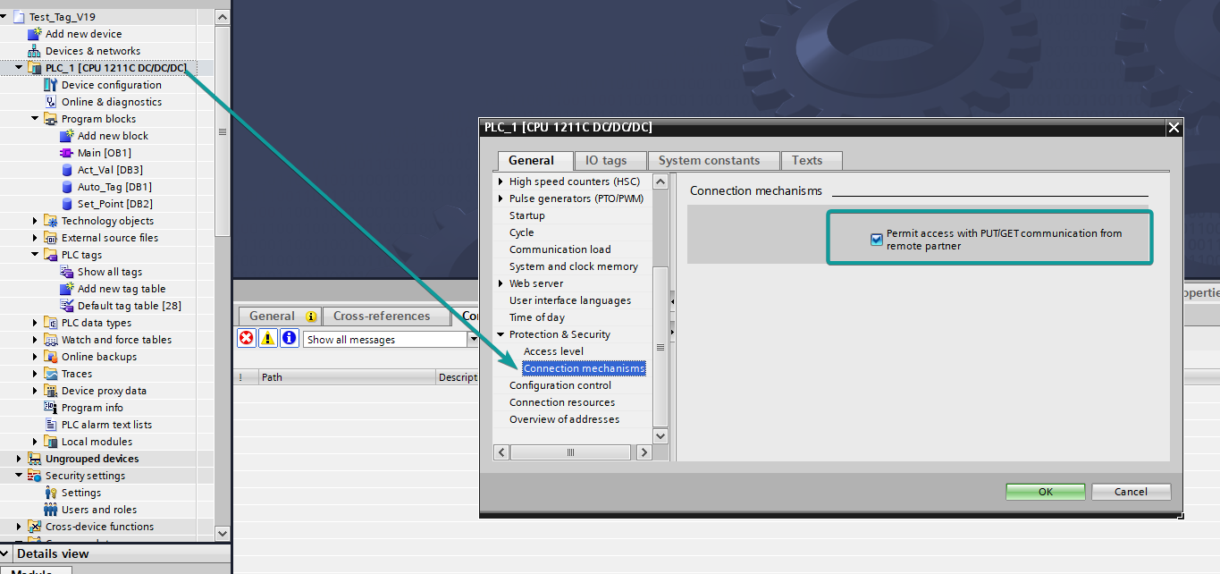
PLC configuration
- Double click [device configuration] in Siemens via software
- Double click [protection] to enter protection configuration screen

- Check [Permit access with PUT / GET communication from remote partner (PLC, HMI, OPC, ...)]
DB settings
- Right click [DB], select [properties]
- Uncheck [optimized block access]
Cable Wiring
S7-XXX Ethernet
Supported Series: Siemens S7-400, S7-1200 and S7-1500
HMI Setting
| Items | Settings | Note |
|---|---|---|
| Protocol | Siemens S7-XXX | |
| Connection | Ethernet | |
| Port No. | 102 | |
| Device No. | Slot (Default 1 for S7-1500/ 2 for S7-1200/ 3 for S7-400) | |
| HMI No. | Rack (Default as 0) |
Slot from TIA Portal is equal to Device No. of PIStudio
Rack from TIA Portal is equal to HMI No. of PIStudio

Check [Permit access with PUT / GET communication from remote partner (PLC, HMI, OPC, ...)]

Address List
| Type | Device register | HMI register | Format | Range | Note |
| Bit | I | I | M d.o | d:0--9999 o:0-7 | |
| Q | Q | Q d.o | d:0--9999 o:0-7 | ||
| M | M | M d.o | d:0--9999 o:0-7 | ||
| DB0.DB-DB99.DB | DBxDB | DBxDBnndddd.o | nn:0-9999, dddd:0-9999, o:0-7 | nn:DB No. dddd:address value o: digit address | |
| Word | M | MB | MB d | d:0-99999 | |
| M | MW | MW d | d:0-99999 | MW0=MB(0~1) MW2=MB(2~3) Address value is a multiple of 2 | |
| M | MD | MD d | d:0-99999 | MD0=MB(0~3) MD4=MB(4~7) Address value is a multiple of 4 | |
| I | IW | IW d | d:0-99999 | ||
| Q | QW | QW d | d:0-99999 | ||
| DB0.DB-DB99.DB | DBxDBB | DBxDBBnndddd | nn:0-9999 dddd:0-9999 | nn:DB No. dddd:address value | |
| DB0.DB-DB99.DB | DBxDBW | DBxDBWnndddd | nn:0-9999 dddd:0-9999 | nn:DB No. dddd:address value Address value is a multiple of 2 | |
| DB0.DB-DB99.DB | DBxDBD | DBxDBDnndddd | nn:0-9999 dddd:0-9999 | nn:DB No. dddd:address value Address value is a multiple of 4 |
Communication Settings
Enable HMI Ethernet in [Project Settings];
Set PLC IP in [Device IP] settings;
✎Note:
- The S7-1200 supports simultaneous connection of three devices, so the driver supports simultaneous access to PLC by three touch screens.
- HMI access PLC, use S7 protocol, access PLC TSAP 02.01 (s7-1200 PROFINET interface only supports three connections, the default support), detailed reference to the system manual of S7-1200.
Cable Wiring

LOGO Ethernet
Supported Series: Siemens Logo 0BA0, 0BA1 series
HMI Settings
| Items | Settings | Note |
| Protocol | Siemens LOGO | |
| Connection | Ethernet | |
| Port No. | 102 | |
| PLC station No. | 2 |
Address List
| Number | Address Type | Data Type | Range | DB Address | PLC Address |
| 1 | RTC | Word | 1-7 | DB1.DBX984.0 | 0x001ec0 |
| 2 | VB | Byte | 0-1469 | DB1.DBX0.0 | 0x000000 |
| 3 | VD | Double Word | 0-1466 | DB1.DBX0.0 | 0x000000 |
| 4 | VW | Word | 0-1468 | DB1.DBX0.0 | 0x000000 |
| 5 | NAQ | Word | 1-32 | DB1.DBX1406.0 | 0x002bf0 |
| 6 | NAI | Word | 1-64 | DB1.DBX1262.0 | 0x002770 |
| 7 | AM | Word | 1-64 | DB1.DBX1118.0 | 0x0022f0 |
| 8 | AQ | Word | 1-16 | DB1.DBX1072.0 | 0x002180 |
| 9 | AI | Word | 1-16 | DB1.DBX1032.0 | 0x002040 |
| 10 | I | Bit | 1-64 | DB1.DBX1024.0 | 0x002000 |
| 11 | Q | Bit | 1-64 | DB1.DBX1064.0 | 0x002140 |
| 12 | M | Bit | 1-112 | DB1.DBX1104.0 | 0x002280 |
| 13 | NI | Bit | 1-128 | DB1.DBX1246.0 | 0x0026f0 |
| 14 | NQ | Bit | 1-128 | DB1.DBX1390.0 | 0x002b70 |
| 15 | V | Bit | 0-14697 | DB1.DBX0.0 | 0x000000 |
PLC Settings in LOGO Software:
Click [Tools]--[Ethernet Connections],shown as below.

Set Ethernet connection parameter. IP, Subnet Mask, shown as below.

TSAP set:The value set by local TSAP is the remote TSAP set in HMI. PLC's remote TSAP is the opposite,shown as below.

Download Project: Click "Address book" to add the IP address to be downloaded (fi."Detect" to check whether the IP address can be detected. Then click “ok”, and the system will prompt that PLC will be "STOP" mode. Click “YES” to start download.

HMI Communication Settings
Set PLC IP in [Device IP] settings;

Enable HMI Ethernet in [Project Settings];

TSAP setting
- Regarding the setting of PLC TSAP, HMI provides system special address for setting, it is recommended to run in HMI script initialization, write PLC TSAP to corresponding system special register.
- HSW10118/HSW1200 = local TSAP of HMI, this is remote TSAP of PLC.
- HSW10119/HSW1201 = Remote TSAP of HMI, this is local TSAP of PLC.
- PI, PI+, i series (1.0 system): use HSW10118, HSW10119.
ie, ig series: use HSW1200, HSW1201.
HMI V2.0: use HSW1200, HSW1201.
✎Note:
- The data of TSAP is hexadecimal format. For example: the remote TSAP configured in the PLC is set to 20.00, then HSW10118/HSW1200 should be set to 0x2000, that is, HSW10118/HSW1200=8192.
- HSW10119/HSW1201 is set up as shown.


- AI word address and Ibit address are read-only and cannot be written on HMI.
- VW address should be even number address, such as VW0, VW2, VW4..., because in the address rule of Siemens PLC, the value of odd number address is equal to the value of previous even number address. For example VW1 = VW0.
- VD address should be multiple of 4, because it occupies two VW addresses, such as VD0, VD4, VD8...
- Written value of RTC cannot exceed 255.
Cable Wiring
S7-300(With PC Adapter)
HMI Setting:
| Parameters | Recommended | Options | Notes |
|---|---|---|---|
| PLC type | SIEMENS S7-300 (with PC Adapter) | ||
| PLC I/F | RS232 | ||
| Baud rate | 19200 | 9600,19200 | |
| Data bits | 8 | ||
| Parity | Odd | ||
| Stop bits | 1 | ||
| PLC sta. no. | 2 | Must be same as the PLC setting. | |
Device Address
| Bit/Word | Device type | Format | Range | Memo |
|---|---|---|---|---|
| Bit | I | DDDDo | 0 ~ 40957 | Input (I) |
| Bit | Q | DDDDo | 0 ~ 40957 | Output (O) |
| Bit | M | DDDDo | 0 ~ 40957 | Bit Memory |
| Word | DB1 to DB99 | DDDDDo | 0 ~ 655327 | |
| Word | IW | DDDD | 0 ~ 4095 | Input (I) |
| Word | QW | DDDD | 0 ~ 4095 | Output (O) |
| Word | MW | DDDD | 0 ~ 4095 | Bit Memory |
| Double word | MD | DDDD | 0 ~ 4094 | |
| Double word | DBDn | FFFFFDDDD | 0 ~ 655359999 | Data Register Double Word (must be even) |
| Byte | MB | DDDD | 0 ~ 4095 | Bit Memory Byte |
Cable Wiring

S7-200 Smart Serial
Supported Series: Siemens S7-200 SMART Series.
Website: http://www.siemens.com/entry/cc/en/
HMI Setting
| Parameters | Recommended | Notes |
|---|---|---|
| PLC type | SIEMENS S7-200 CPU22x/Smart PPI new | |
| PLC I/F | RS485 | |
| Baud rate | 9600 | |
| Data bits | 8 | |
| Parity | EVEN | |
| Stop bits | 1 | |
| PLC sta. no. | 2 | Must be same as the PLC setting. |
Address List
| Type | Device registers | HMI registers | Format | Range | Note |
|---|---|---|---|---|---|
| Bit | I | I | I d | 0~99999 | |
| Q | Q | Q d | 0~99999 | ||
| VWBit | VWBit | VWBit d | 0~99999 | ||
| V | V | V d | 0~99999 | ||
| M | M | M d | 0~99999 | ||
| SM | SM | SM d | 0~99999 | ||
| S | S | S d | 0~99999 | ||
| T | T | T d | 0~99999 | ||
| C | C | C d | 0~99999 | ||
| Word | IW | IW | IW d | 0~99998 | |
| QW | QW | QW d | 0~99998 | ||
| AIW | AIW | AIW d | 0~99998 | ||
| AQW | AQW | AQW d | 0~99998 | ||
| VW | VW | VW d | 0~99998 | ||
| MW | MW | MW d | 0~30 | ||
| SW | SW | SW d | 0~99998 | ||
| SMW | SMW | SMW d | 0~99998 | ||
| TW | TW | TW d | 0~99999 | ||
| CW | CW | CW d | 0~99999 |
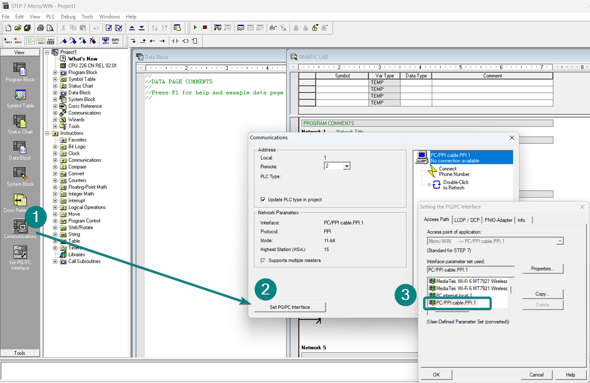
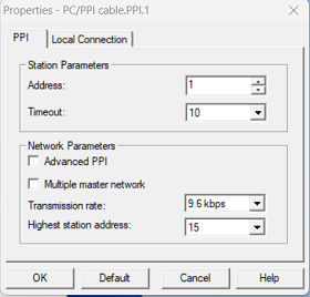
Configure the communication protocol


PLC Settings
Select "Set PG/PC Interface" in Communication of the View list and Set PG/PC Interface.
Select PC/PPI cable PPI.1 and set communication parameters.
Cable Wiring

Pin Definition Diagram

S7-200(Ethernet with 243)
Supported Series: Siemens S7-200(Ethernet with 243)
HMI Setting
| Items | Settings | Note |
|---|---|---|
| Protocol | Siemens S7-200(Ethernet with 243) |
|
| Connection | Ethernet | |
| Port No. | 102 | |
| PLC station No. | 2 |
Address List
| Bit/Word | Device type | Address NO. | Range | Note |
|---|---|---|---|---|
| Bit | I | DDDD.o | D:0~99999 o:0~7 | |
| Q | DDDD.o | D:0~99999 o:0~7 | ||
| M | DDDD.o | D:0~99999 o:0~7 | ||
| V | DDDD.o | D:0~99999 o:0~7 | ||
| VWBit | DDDD.o | D:0~99999 o:0~7 | ||
| SM | DDDD.o | D:0~65535 o:0~7 | ||
| S | DDDD.o | D:0~99999 o:0~7 | ||
| T | DDDD | 0~99999 | ||
| C | DDDD | 0~99999 | ||
| Lamp | 0 | 0 | ||
| Word | IW | DDDD | 0~99999 | |
| QW | DDDD | 0~99999 | ||
| AIW | DDDD | 0~99999 | ||
| AQW | DDDD | 0~99999 | ||
| VW | DDDD | 0~99998 | ||
| MW | DDDD | 0 ~ 30 | ||
| TW | DDDD | 0~99999 | ||
| CW | DDDD | 0~99999 | ||
| SW | DDDD | 0~99999 | ||
| Double word | MD | DDDD | 0-28 | |
| VD | DDDD | 0 ~ 99998 |
Viewing/Configuring Ethernet Parameters
1.[Tools]--[Ethernet Wizard]
2.Choose the position of module 243 --[Next]

3.Choose the module type,Next
4.Set IP address as 192.168.1.218 ,and Subnet mask as 255.255.255.0,Next
5.[QB]1--[Number of connections to configure for this module]3--[Next]

6.Click [This is a Server Connection] and Click [Accept all connection requests],[OK]

7.Click [Yes,generate CRC protection for this configuration in the data book],set the Keep Alive Interval as 30 sec,[Next]

8.Choose the Suggest Address,Next

9.[ETH Configuration for 0]--[Finish]

Test CP 243-1
1.[Communications]→[PC/PPI cable]→[TCPIP.1]→[OK]

2.[Remote]192.168.1.218 then [Double-Click to Refresh]and choose[CPU 226 CN REL 02.01 192.168.1.218],click[OK]

Cable Wiring

Siemens S7-1200/1500 Ethernet Free Tag
HMI Setting
| Items | Settings | Note |
| Protocol | Siemens S7-1200/1500 Ethernet FreeTag | |
| Connection | Ethernet | |
| Port No. | 102 | |
| PLC station No. | 1 |
Support Variable Type
| Data Type | PIStudio Data Format |
|---|---|
| BOOL | Bit |
| BYTE | 16-bit Unsigned/Binary/BCD/Hex |
| WORD | 16-bit Unsigned/Binary/BCD/Hex |
| DWORD | 32-bit Unsigned/Binary/BCD/Hex |
| SINT | 16-bit Signed/Binary/BCD/Hex |
| USINT | 16-bit Unsigned/Binary/BCD/Hex |
| INT | 16-bit Signed/Binary/BCD/Hex |
| UINT | 16-bit Unsigned/Binary/BCD/Hex |
| DINT | 32-bit Signed/Binary/BCD/Hex |
| UDINT | 32-bit Unsigned/Binary/BCD/Hex |
| STRING | Max:256 |
| Real | 32-bit Float |
| Struct | Bool/Byte/SINT/USINT/WORD/INT/UINT/DWord/DINT/Real/UDINT/String |
| Array | Bool/Byte/SINT/USINT/WORD/INT/UINT/DWord/DINT/Real/DINT/String |
Communication Settings
Communication → choose "Siemens S7-1200/1500 Ethernet FreeTag" → OK

Setting→ PLC IP Address → OK

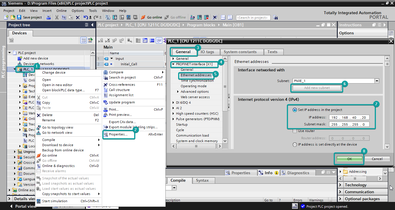
PLC Setting
In the Project tree [PLC project]→Right-click[PLC-1]→[Properties]→[General]→[PROFINE interface]→[Add new subnet]→[IP address]192.168.40.20,[Subnet mask]255.255.255.0→[OK]
Open [Properties] again→[General]→[Protection&Security]→[Connection mechanisms]→Check [Permit access with PUTIGET communication remote partner ]→[OK]
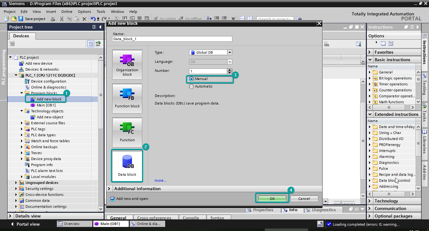
Create a new DB block:
[Add new block]→[Date block]→[Manual]→[OK]
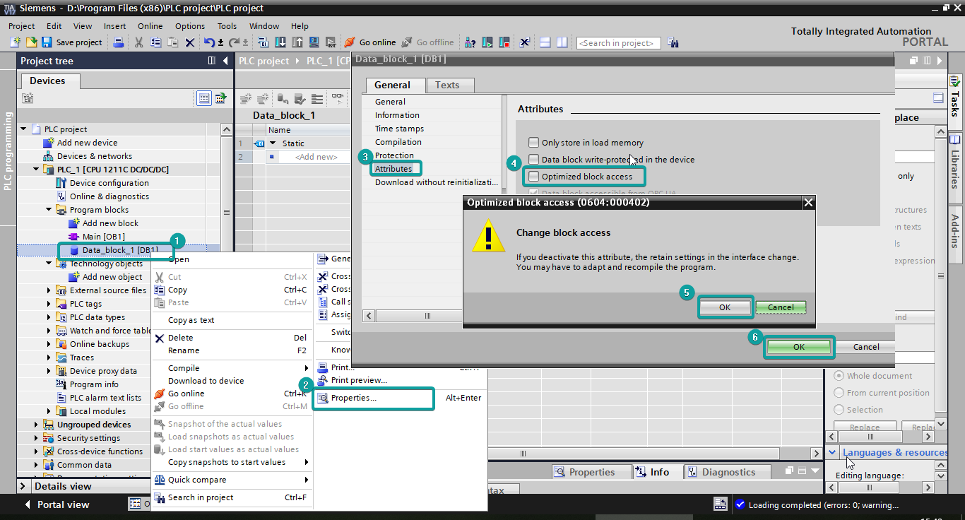
Right-click[DB1]→[Properties]→[General]→[Attributes]→Uncheck[Optimized block access]→[OK]
How to import the tags:
Click DB block → create FreeTags → Project→ Save as the file in a path


Communication→ Labels manage→ Import Tags From File→ choose PLC program→ Open
