12 PLC Protocol OLD
Introduction
This chapter contains information on configuring the communication between device and HMI.
General Procedure
During configuring communication in PIStudio. The following components and conditions is indeed at least.
- One PI HMI
- One connected controller (for example PLC)
- One Cable Wiring

User need to select controller protocol and set communication parameters in HMI project. Please note to set same communication parameter between controller and HMI project. After finishing project, user could download HMI project into HMI and connect HMI with controller by Cable Wiring. Thena simple automation system would be established.
Communication Settings
For example, controller is WECON LX3V series PLC and HMI is PI8070. Please set communication protocol, and set communication parameters in the [Communication].
Timeout
The follwoing are description for the timeout settings from [Communication].

- Wait Timeout(ms): The time HMI waits for a response from the PLC.
- Receive Timeout(ms): The longest waiting interval between the HMI receiving two characters.
- Retry Count: The number of retries when there is no response in the communication between HMI and PLC.
- Retry Timeout(s): The PLC will not be accessed during the Retry Timeout period when there is no response in the communication between HMI and PLC.
- Delay Time(ms): The speed at which the HMI communicates with the device.
- Continuous Length: Default value 0 means the maximum length specified by each protocol. Addresses dealt by Maximum Span settings, its read length for single time, if the Continouous Length is 1, which means it will read/write the every register one by one. If the length of Maximum Span is greater than or equal to the Continuous Length, the continuous read/write will be performed in groups according to Continuous Length.
- Maximum Span: Set the interval for reading PLC addresses. If there exists two same register type addresses, their interval is less than the set value of Maximum Span, then they will be integrated into a continuous address, otherwise it will be divide into two independent addresses.
Operating Procedure
After creating the [Quick_Start] project,select the [Project]->[Communication].

Click “Setting” to open protocol setting windows.

Select communication protocol, users could select serial port, Ethernet port, CAN port or USB.
- Serial port:

- Ethernet port:

- CAN port (In COM1):

- USB port:

About parameters for communication, PLC default communication parameters have been written to PIStudio, the user can adjust them according to the actual situation.
- Serial port:

- Ethernet port
Please note, during using Ethernet port, please set HMI IP in [Project Setting], the detailed, please refer to [Project Setting] chapter.

Click [OK] button to save settings and close the dialog;
Limitation for Ethernet communication protocol
The table below shows the maximum number of communications configured for the general protocol,Free Tag Protocol and CodeSys V3 Protocol on each series model.
(Only HMI V2.0 System supports Free Tag Protocol and CodeSys V3 Protocol)
| HMI Series | General Protocol | FreeTags Protocol | CodeSys V3 Protocol |
|---|---|---|---|
| General 3000 Series | 16 | N/A | N/A |
| General 8000 Series | 24 | 4 | N/A |
| General 9000 Series | 32 | N/A | N/A |
| PI3000i Series | 16 | N/A | N/A |
| PI3000ie Series (PI3043ieS-N) | 16 | 2 | N/A |
| PI3000ie Series (other model) | N/A | N/A | N/A |
| PI3000ig Series (PI3070ig-O & PI3102ig-O) | 16 | N/A | N/A |
| PI3000ig Series (other model) | 16 | 4 | 2 |
| PI8000ig Series | 32 | 6 | 2 |
WECON
LX3 Series
Supported series: WECON LX2V/ LX2E/ LX3V/LX3VP/LX3VE/LX3VM
HMI Settings
| Item | Settings | Note |
|---|---|---|
| Protocol | WECON LX2V/ LX2E/ LX3V/LX3VP/LX3VE/LX3VM | |
| Connection | RS422/RS485 | |
| Baud rate | 9600 | |
| Data bit | 7 | |
| Parity | EVEN | |
| Stop bit | 1 | |
| PLC station No. | 1 |
Address List
| Type | Device registers | HMI registers | Format | Range | Note |
|---|---|---|---|---|---|
| Bit | X | X | Xo | 0~303237 | |
| Y | Y | Y o | 0~303237 | ||
| M | M | M d | 0~99999 | ||
| T | T | T d | 0~99999 | ||
| C | C | C d | 0~99999 | ||
| S | S | S d | 0~99999 | ||
| Word | X | X | Xo | 0~303237 | |
| Y | Y | Y o | 0~303237 | ||
| M | M | M d | 0~99999 | ||
| T | T | T d | 0~99999 | ||
| C | C | C d | 0~199 | ||
| D | D | D d | 0~7999 | ||
| S | S | S d | 0~99999 | ||
| SD | SD | SD d | 8000~9999 |
Cable Wiring
- RS485

- RS422

HMI settings
Download PIStudio Software
Please visit the link below to get the latest version PIstudio for HMI programming:
Create a new HMI project connect with PLC
Check the link below for the video to show you how to get started with a new project
For more videos, please visit our Youtube channel: http://www.youtube.com/user/Wecon2004/videos
General
HMI could communicate with PLC and support many PLC protocols. It is easy to operate and set communication parameters. This demo shows how to make a communication with PLC device, use WECON LX3V Series PLC as an example.
Protocol settings
The communication between two devices requires a protocol. The following contents show the steps of protocol settings.
Please select the protocol, when creating a new project.
- Select the COM port for communication;
- PLC type: It means PLC brand, like WECON;
- PLC model: It shows the model of PLC, such as LX3V;

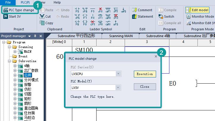
If you want to change the protocol for existing project, please click [Project] → [Communication] to open the [Communication] windows, shown as the following figure.

The steps to change the protocol for project are as follows.
- Click [Setting] to open the [Communication device] window;
- Select communication port, such as COM1;
- Select Serial port for communication, such as RS422;
- Select device type (device brand), such as WECON;
- Select the protocol for communication, such as WECON LX3V;

Parameter settings
The parameters settings are in [Communication] window, shown as following below.
- Click [Setting] to open the [COM port setting] window;
- Set the parameters such as [connection], [Baud rate] and so on;

- Click [Setting] to open [Timeout] setting window, you could set the parameters according your requirements, or just use the default value.

Set PLC address in HMI screen
- Place the objects to HMI screen;
- Double-click the object to open the setting window;
- Click “Edit” to open the address setting windows;
- Connection: select the serial port in HMI;
- Address type: All the PLC address types will be display in this list, such as M;
- Address No.: Please input the number of this address, such as 0;

HMI Compilation Download

Communication cable
In order to ensure the stability of communication, please use the twisted-pair communication cable with good grounding. The following figure shows the pin out definition.

HMI communication PLC use Modbus
- HMI setting: https://docs.we-con.com.cn/bin/view/PIStudio/12.PLC%20protocols/
- PLC setting: https://docs.we-con.com.cn/bin/view/PLC%20Editor/8.1.%09Communication/
PLC settings
Download PLC Software
Please visit below link to get the latest version PLC Editor for HMI programming
- LX3V:Download link
- LX5V:Download link
Start a new PLC project
Start a new PLC project by clicking “New” on the left top corner of screen, select the PLC mode from the drop-down list.
Add a new instruction
Double click on the ladder, select the ladder symbol (instruction) from the drop-down list, then enter the address for this symbol.

You could also select the ladder symbol from the menu bar directly.

Add comment to PLC program

Add the statement to PLC program
Add the statement by single click on “Statement”, when finished, single click on “Statement” again to go back to Ladder edit.

Compile
You need to compile the PLC program before downloading or running Off-line simulator. The background color will be changed from purple to white when there is no error.

Download setting
Click on “Transfer Setup” to select download mode.
 Download PLC program to PLC
Quick select the parameters and main program of PLC program, then download to PLC, “Yes”-”Yes”-”OK”

Upload PLC program from PLC
Read the PLC program from PLC to computer.

Device monitor
Monitor the value of certain address in PLC, double click “Current value” to change the value in this address.

Online monitor
Monitor the each address in PLC by online monitor. Changing the state or value in PLC is also allowd.

Monitor edit
In this mode, you could edit the PLC program during PLC is running.

LX5V Series
This example introduces the establishment of serial port communication between Wecon HMI and LX5V, including three parts: PLC software configuration, HMI software configuration, and hardware wiring.
Software configuration of PLC
PLC programming software

New PLC project
Click "New Project" and select the PLC model.

Set Serial port parameters
Follow the steps below to configure Serial port parameters.
- Baud rate:115200
- Data bit:8
- Stop bit:1
- Parity:No verification

Registers list

HMI software configuration
HMI programming software

New HMI project
Click New Project and select the HMI model.

Set communication port parameters
Click the communication configuration button on the left to find the communication protocol with LX5V. After selecting the protocol, configure the communication parameters of the COM port.
- Baud rate:115200
- Data bit:8
- Stop bit:1
- Parity:No verification

hardware connection
Hardware wiring diagram
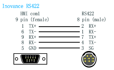
This example introduces WeconHMI with LX5V PLC to establish communication through serial port. The connection diagram is as follows:


The above are all the steps for establishing serial port communication between Wecon HMI with LX5V PLC.
LX5V-N Ethernet
This example introduces the establishment of Ethernet communication between Wecon HMI and LX5V, including three parts: PLC software configuration, HMI software configuration, and hardware wiring.
Software configuration of PLC
PLC programming software
New PLC project
Click New Project and select the PLC model.

Set Ethernet port parameters
Follow the steps below to configure Ethernet parameters
- PLC IP address:192.168.39.200
- default gateway:192.168.39.1
- subnet mask:255.255.255.0

Registers list
HMI software configuration
HMI programming software
New HMI project
Click New Project and select the HMI model.
Set communication port parameters
Click the project setting button on the left to configure the IP address of the HMI machine to ensure that the HMI and PLC IP remain in a local area network.
- HMI IP address:192.168.39.201
- Default gateway:192.168.39.1
- Subnet mask:255.255.255.0

Next, click Communication Settings to configure the IP of the HMI communication object.

Hardware connection
This example introduces WeconHMI with LX5V-N PLC to establish communication through ethernet. The connection diagram is as follows:

The above are all the steps for establishing ethernet communication between Wecon HMI with LX5V PLC.
ABB
AC500
Support Series: ABB AC500
HMI Settings
| Item | Recommended | Note |
|---|---|---|
| Protocol | ABB AC500 | |
| Connection | RS232 | |
| Baud rate | 19200 | |
| Stop bits | 1 | |
| Data bits | 8 | |
| Parity | EVEN | |
| PLC Station No. | 1 | |
| HMI Station No. | 0 |
Address List
| Type | Device registers | Format | Range | Note |
|---|---|---|---|---|
| Bit | MX | MXdddd.oo | 0.0~8191.7 | |
| Word | MW0 | MW0ddddd | 0~32767 | |
| MW1 | MW1ddddd | 0~32767 |
Cable Wiring

Abzil
Abzil CPL Protocol
Supported series: SDC series
HMI Settings
| Item | Settings | Note |
| Protocol | Abzil CPL | |
| Connection | RS485 | |
| Baud rate | 9600 | |
| Data bit | 8 | |
| Parity | EVEN | |
| Stop bit | 1 | |
| PLC station No. | 0 |
Address List
| Type | Device registers | Format | Range | Note |
| Bit | 00 | 00DDDD.h | 0~9999.f | |
| 01 | 01DDDD.h | 0~9999.f | ||
| 02 | 02DDDD.h | 0~9999.f | ||
| 03 | 03DDDD.h | 0~9999.f | ||
| 04 | 04DDDD.h | 0~9999.f | ||
| 05 | 05DDDD.h | 0~9999.f | ||
| 06 | 06DDDD.h | 0~9999.f | ||
| 07 | 07DDDD.h | 0~9999.f | ||
| 08 | 08DDDD.h | 0~9999.f | ||
| Word | 00 | 00DDDD | 0~9999 | |
| 01 | 01DDDD | 0~9999 | ||
| 02 | 02DDDD | 0~9999 | ||
| 03 | 03DDDD | 0~9999 | ||
| 04 | 04DDDD | 0~9999 | ||
| 05 | 05DDDD | 0~9999 | ||
| 06 | 06DDDD | 0~9999 | ||
| 07 | 07DDDD | 0~9999 | ||
| 08 | 08DDDD | 0~9999 |
Cable Wiring

Crouzet
M3 (FBD)
Support Series: Crouzet Millenium 3 CD12/CB12
HMI Settings
| Item | Recommended | Note |
|---|---|---|
| Protocol | CROUZET M3 (FBD) | |
| Connection | RS232 | |
| Baud rate | 115200 | |
| Stop bits | 1 | |
| Data bits | 7 | |
| Parity | EVEN | |
| PLC Station No. | 1 | |
| HMI Station No. | 0 |
Address List
| Type | Device registers | Format | Range | Note |
|---|---|---|---|---|
| Bit | I | I DD | 1~99 | Input |
| SLIBit | SLIBit DD.dd | 1.0~24.15 | Serial Link Input | |
| SLOBit | SLOBit DD.dd | 25.0~48.15 | Serial Link Output(Read only) | |
| State | State D | 1~1 | PLC state(Read only) | |
| Word | AI | AI DD | 1~99 | Analog Input |
| SLIn | SLIn DD | 1~24 | Serial Link Input | |
| SLOut | SLOut DD | 25~48 | Serial Link Output(Read only) | |
| Time | Time D | 1~6 | Time1: Second Time2: Minute Time3: Hour Time4: Day Time5: Month Time6: Year | |
| Order | Order D | 1~1 | Running command(Write only) =2: Run mode; =1: Stop mode; |
Cable Wiring

Danfoss
FC Series
Support Series: VLT FC300 Drive
HMI Settings
| Item | Recommended |
|---|---|
| Protocol | Danfoss FC Series |
| Connection | RS485 |
| Baud rate | 9600 |
| Stop bits | 1 |
| Data bits | 8 |
| Parity | EVEN |
| PLC Station No. | 1 |
| HMI Station No. | 0 |
Address List
| Type | Device registers | Format | Range | Note |
|---|---|---|---|---|
| Word | P | P dddd | 0~4095 | |
| E | E dddd | 0~4095 | ||
| S | S d | 0~1 | ||
| C | C d | 0~1 |
Cable Wiring

Delta
DVP Series
Supported Series: Delta DVP EH/ES/SS/EX/EH2/SV/SA/SC/SX Controller
HMI Settings
| Item | Settings | Note |
|---|---|---|
| Protocol | DELTA DVP Series | |
| Connection | RS485 | |
| Baud rate | 9600 | |
| Data bit | 7 | |
| Parity | Even | |
| Stop bit | 1 | |
| PLC station No. | 1~255 | Need to be the same as PLC settings |
Address List
| Type | Device registers | HMI registers | Format | Range | Note |
|---|---|---|---|---|---|
| Bit | X | X | X d | 0~303237 | |
| Bit | Y | Y | Y d | 0~303237 | |
| Bit | M | M | M d | 0~99999 | |
| Bit | T | T | T d | 0~99999 | |
| Bit | C | C | T d | 0~99999 | |
| Bit | S | S | T d | 0~99999 | |
| Word | D | D | D d | 0~99999 | |
| Word | T | T | T d | 0~99999 | |
| Word | C | C | C d | 0~99999 |
Configure the communication protocol


Cable Wiring

DVP Modbus TCP
Supported Series: Delta DVP ES2/EX2/SS2/SA2/SX2/SE Controller
HMI Settings
| Items | Settings | Note |
|---|---|---|
| Protocol | DELTA DVP Modbus TCP | |
| Connection | Ethernet | |
| Port No. | 201 | Must be the same as the PLC setting |
| PLC station No. | 0 | Must be the same as the PLC setting |
Address List
| Type | Device registers | HMI registers | Format | Range | Note |
|---|---|---|---|---|---|
| Bit | X | X | X o | 0~377 | |
| Bit | Y | Y | Y o | 0~377 | |
| Bit | M0 | M0 | M0 d | 0~1535 | |
| Bit | M1 | M1 | M1 d | 1536~4095 | |
| Bit | T | T | T d | 0~255 | |
| Bit | C | C | C d | 0~255 | |
| Bit | S | S | S d | 0~1023 | |
| Word | D0 | D0 | D0 d | 0~4095 | |
| Word | D1 | D1 | D1 d | 4096~11999 |
|
| Word | T | T | T d | 0~255 | |
| Word | C | C | C d | 0~199 |
|
Configure the communication protocol


Cable Wiring

AS300 MODBUS RTU
Supported Series: Delta AS200/AS300
HMI Settings
| Item | Settings | Note |
| Protocol | DELTA AS300 MODBUS RTU | |
| Connection | RS485 | |
| Baud rate | 9600 | |
| Data bit | 8 | |
| Parity | NONE | |
| Stop bit | 1 | |
| PLC station No. | 1 |
Address List
| Type | Device registers | HMI registers | Format | Range | Note |
|---|---|---|---|---|---|
| Bit | X | X | Xdd.dd | 0~63.15 | Read only |
| Bit | Y | Y | Ydd.dd | 0~63.15 | |
| Bit | D | D | Dddddd | 0~29999 | |
| Bit | M | M | Mdddd | 0~8191 | |
| Bit | SM | SM | SMdddd | 0~4095 | |
| Bit | S | S | Sdddd | 0~2047 | |
| Bit | T | T | Tddd | 0~511 | |
| Bit | C | C | Cddd | 0~511 | |
| Bit | HC | HC | HCddd | 0~255 | Double Word |
| Word | X | X | Xdd | 0~63 | |
| Word | Y | Y | Ydd | 0~63 | |
| Word | SR | SR | SRdddd | 0~2047 | Special register |
| Word | D | D | Dddddd | 0~29999 | |
| Word | T | T | Tddd | 0~511 | |
| Word | C | C | Cddd | 0~511 | |
| Word | E | E | Ed | 0~9 |
Configure the communication protocol
Create project

Open the tool COMMGR, to communicate with PLC, if know the IP, we can directly click Add to input PLC IP. Or search the PLC IP from LAN.

Double click the HWCONFIG to open the communication settings window.

Expand the Project Tree, open the hardware configuration, double click the PLC icon.

Click COM1 Port Setting, the default Modbus mode is ASCII, need to change to RTU.

Click Ethernet Port Basic Setting, set the PLC IP and Gateway. Make sure the IP and Gateway is same segment. Then download into PLC.


Cable Wiring

Pin Definition Diagram

AS300 MODBUS TCP
HMI Settings
| Items | Settings | Note |
|---|---|---|
| Protocol | DELTA AS300 MODBUS TCP | |
| Connection | Ethernet | |
| Port No. | 502 | |
| Device No. | 1 | |
| HMI No. | 0 |
Address List
| Type | Device registers | HMI registers | Format | Range | Note |
|---|---|---|---|---|---|
| Bit | X | X | X d | 0~63 | |
| Bit | Y | Y | Y d | 0~63 | |
| Bit | D | D | D d | 0~29999 | |
| Bit | M | M | M d | 0~8191 | |
| Bit | SM | SM | SM d | 0~4095 | |
| Bit | S | S | S h | 0~2047 | |
| Bit | T | T | T d | 0~511 | |
| Bit | C | C | C d | 0~511 | |
| Bit | HC | HC | HC d | 0~255 | |
| Word | X | X | X h | 0~63 | |
| Word | Y | Y | Y d | 0~63 | |
| Word | SR | SR | SR d | 0~2047 | |
| Word | D | D | D d | 0~29999 | |
| Word | T | T | T d | 0~511 | |
| Word | C | C | C h | 0~511 | |
| Word | E | E | E d | 0~9 |
Configure the communication protocol


Cable Wiring
EMERSON
RTU Slave Protocol
Supported series: EC10 series
HMI Settings
| Item | Settings | Note |
| Protocol | Emerson 984 RTU Slave MODBUS | |
| Connection | RS485 | |
| Baud rate | 19200 | |
| Data bit | 8 | |
| Parity | EVEN | |
| Stop bit | 1 | |
| PLC station No. | 1 |
PLC Settings
Remember to use the Control Star to enable the Modbus RTU communication for port 1 in system block before dowload into PLC.


Address List
| Type | Device registers | Format | Range | Note |
| Bit | Y | YOOO | 0~377 | |
| X | XOOO | 0~377 | ||
| M0 | M0DDDD | 0~2047 | ||
| M1 | M1DDDDD | 2048~10239 | ||
| SM0 | SM0DDD | 0~255 | ||
| SM1 | SM1DDD | 256~511 | ||
| S0 | S0DDDD | 0~1023 | ||
| S1 | S1DDDD | 1024~4095 | ||
| T0 | T0DDD | 0~255 | ||
| T1 | T1DDD | 256~511 | ||
| C0 | C0DDD | 0~255 | ||
| C1 | C1DDD | 256~306 | ||
| Word | D | DDDDD | 0~7999 | |
| Z | ZDD | 0~15 | ||
| TW0 | TW0DDD | 0~255 | ||
| TW1 | TW1DDD | 256~511 | ||
| SD0 | SD0DDD | 0~255 | ||
| SD1 | SD1DDD | 256~511 | ||
| CW | CWDDD | 0~306 | ||
| Double Word | CW0 | CW0DDD | 200~255 | |
| CW1 | CW1DDDDD | 256~99999 |
Cable Wiring

HollySys
LK MODBUS RTU
Supported Series: HollySys LK series CPU
HMI Settings
| Item | Recommended | Note |
|---|---|---|
| Protocol | HollySys LK MODBUS RTU | |
| Connection | RS485 | |
| Baud rate | 38400 | |
| Stop bits | 1 | |
| Data bits | 8 | |
| Parity | NONE | |
| PLC Station No. | 1 | |
| HMI Station No. | 0 |
Address List
| Type | Device registers | Format | Range | Note |
|---|---|---|---|---|
| Bit | QX | QXDDDDD.dd | 0~65535.15 | |
| Bit | IX | IXDDDDD.dd | 0~65535.15 | |
| Bit | MX | MXDDDDD.dd | 0~65535.15 | |
| Word | QW | QWDDDDD | 0~99999 | |
| Word | IW | IWDDDDD | 0~99999 | |
| Word | MW | MWDDDDD | 0~99999 | |
| Word | MD | MDDDDDD | 0~99999 |
Cable Wiring

LM MODBUS RTU
Supported Series: HollySys LM3109/LM3107 PLC
HMI Settings
| Item | Recommended | Optional | Note |
|---|---|---|---|
| Protocol | HollySys LM MODBUS RTU | HollySys LM MODBUS RTU | |
| Connection | RS232 | RS485 | |
| Baud rate | 38400 | 38400 | |
| Stop bits | 1 | 1 | |
| Data bits | 8 | 8 | |
| Parity | NONE | NONE | |
| PLC Station No. | 51 | 51 | |
| HMI Station No. | 0 | 0 |
Address List
| Type | Device registers | Format | Range | Note |
|---|---|---|---|---|
| Bit | QX | QXDDDDD.oo | 0~65535.7 | |
| Bit | IX | IXDDDDD.oo | 0~65535.7 | |
| Bit | MX | MXDDDDD.oo | 0~65535.7 | |
| Word | QW | QWDDDDD | 0~99999 | |
| Word | IW | IWDDDDD | 0~99999 | |
| Word | MW | MWDDDDD | 0~99999 | |
| Word | MD | MDDDDDD | 0~99999 |
Cable Wiring
RS232

RS485

Inovance
H1U/H2U Serial
HMI Settings
| Item | Recommended | Note |
|---|---|---|
| Protocol | INOVANCE H1U PLC/INOVANCE H2U PLC | |
| Connection | RS422 | |
| Baud rate | 9600 | |
| Stop bits | 1 | |
| Data bits | 7 | |
| Parity | EVEN | |
| PLC Station No. | 1 | |
| HMI Station No. | 0 |
Address List
| Type | Device registers | Format | Range | Note |
|---|---|---|---|---|
| Bit | X | XOOOOOO | 0~303237 | Input Bit |
| Bit | Y | YOOOOOO | 0~303237 | Output Bit |
| Bit | M | MDDDDD | 0~99999 | Auxiliary |
| Bit | T | TDDDDD | 0~99999 | Timer |
| Bit | C | CDDDDD | 0~99999 | Counter |
| Bit | SM | SMDDDD | 8000~9999 | Special Auxiliary |
| Bit | S | SDDDDD | 0~99999 | |
| Bit | Lamp | Lamp0 | 0~0 | Communication Indicator |
| Word | X | X OOOOOO | 0~303237 | Input Word |
| Word | Y | Y OOOOOO | 0~303237 | Output Word |
| Word | M | M DDDDD | 0~99999 | Auxiliary |
| Word | T | T DDDDD | 0~99999 | Timer |
| Word | C | C DDD | 0~199 | Counter |
| Word | D | D DDDD | 0~7999 | Data Register |
| Word | S | S DDDDD | 0~99999 | |
| Word | SD | SD DDDD | 8000~9999 | Special Data Register |
| Double Word | CH | CH DDD | 200~255 |
Cable Wiring
H3U Serial
HMI Settings
| Item | Settings | Note |
|---|---|---|
| Protocol | INOVANCE H3U PLC | |
| Connection | RS422 | |
| Baud rate | 9600 | |
| Data bit | 7 | |
| Parity | EVEN | |
| Stop bit | 1 | |
| PLC station No. | 0 |
Address List
| Type | Device registers | Format | Range | Note |
|---|---|---|---|---|
| Bit | X | X OOOOOO | 0~303237 | |
| Bit | Y | Y OOOOOO | 0~303237 | |
| Bit | M | M DDDDD | 0~99999 | |
| Bit | T | T DDDDD | 0~99999 | |
| Bit | C | C DDDDD | 0~99999 | |
| Bit | SM | SM DDDD | 8000~9999 | |
| Bit | S | S DDDDD | 0~99999 | |
| Bit | Lamp | Lamp0 | 0~0 | |
| Word | X | X OOOOOO | 0~303237 | |
| Word | Y | Y OOOOOO | 0~303237 | |
| Word | M | M DDDDD | 0~99999 | |
| Word | T | T DDDDD | 0~99999 | |
| Word | C | C DDD | 0~199 | |
| Word | D | D DDDD | 0~7999 | |
| Word | S | S DDDDD | 0~99999 | |
| Word | SD | SD DDDD | 8000~9999 | |
| Word | R | R DDDDD | 0~32767 | |
| Double Word | CH | CH DDD | 200~255 |
Configure the communication protocol


Cable Wiring
H3U Ethernet
HMI Settings
| Item | Settings | Note |
|---|---|---|
| Protocol | INOVANCE H3U PLC Ethernet | |
| Connection | Ethernet | |
| Port No. | 502 | |
| Device No. | 1 | |
| HMI No. | 0 |
Address List
| Type | Device registers | Format | Range | Note |
|---|---|---|---|---|
| Bit | M | M DDDD | 0~8511 | |
| Bit | SM | SM DDDD | 0~1023 | |
| Bit | S | S DDDD | 0~4095 | |
| Bit | T | T DDD | 0~511 | |
| Bit | C | C DDD | 0~255 | |
| Bit | X | X OOO | 0~571 | |
| Bit | Y | Y OOO | 0~571 | |
| Word | D | D DDDD | 0~8511 | |
| Word | SD | SD DDDD | 0~1023 | |
| Word | R | R DDDDD | 0~32767 | |
| Word | T | T DDD | 0~255 | |
| Word | C | C DDD | 0~199 | |
| Double Word | C | C DDD | 200~255 |
Cable Wiring

LS
XGB Serial
HMI Settings
| Item | Settings | Note |
|---|---|---|
| Protocol | LS XGB CPU DRIECT | |
| Connection | RS232 | |
| Baud rate | 115200 | |
| Data bit | 8 | |
| Parity | NONE | |
| Stop bit | 1 | |
| PLC station No. | 1 |
Address List
| Type | Device registers | HMI registers | Format | Range | Note |
|---|---|---|---|---|---|
| Bit | P | P | P DDDD.f | 0~2047 | |
| Bit | M | M | M DDDD.f | 0~2047 | |
| Bit | L | L | L DDDDD.f | 0~11263 | |
| Bit | K | K | K DDDD.f | 0~2559 | |
| Bit | F | F | F DDDD.f | 0~2047 | |
| Bit | S | S | S DDDDD | 0~12799 | |
| Bit | D | D | D DDDDD.f | 0~32767 | |
| Bit | U | U | U FFFF.f | 0~7f31 | |
| Bit | T | T | T DDDD.f | 0~2047 | |
| Bit | C | C | C DDDD.f | 0~2047 | |
| Word | P | P | P DDDD | 0~2047 | |
| Word | M | M | M DDDD | 0~2047 | |
| Word | L | L | L DDDDD | 0~11263 | |
| Word | K | K | K DDDD | 0~2559 | |
| Word | F | F | F DDDD | 0~2047 | |
| Word | C | C | C DDDD | 0~2047 | |
| Word | T | T | T DDDD | 0~2047 | |
| Word | D | D | D DDDDD | 0~32767 | |
| Word | N | N | N DDDDD | 0~21503 | |
| Word | U | U | U FFFF | 0~7f31 | |
| Word | Z | Z | Z DDD | 0~127 | |
| Word | R | R | R DDDDD | 0~32767 | |
| Word | ZR | ZR | Z DDDDD | 0~32767 | |
| Word | TS | TS | TS DDDD | 0~2047 | |
| Word | CS | CS | CS DDDD | 0~2047 | |
| Word | S | S | S DDDDD | 0~12799 |
Configure the communication protocol


Pin Definition Diagram

XBC Serial
HMI Settings
| Item | Settings | Note |
|---|---|---|
| Protocol | LS XBC CNet | |
| Connection | RS232 | |
| Baud rate | 115200 | |
| Data bit | 8 | |
| Parity | NONE | |
| Stop bit | 1 | |
| PLC station No. | 1 |
Address List
| Type | Device registers | HMI registers | Format | Range | Note |
|---|---|---|---|---|---|
| Bit | P | P | P d | 0~2047 | |
| Bit | M | M | M d | 0~2047 | |
| Bit | L | L | L d | 0~11263 | |
| Bit | K | K | K d | 0~16183 | |
| Bit | F | F | F d | 0~2047 | |
| Bit | D | D | D d | 0~32767 | |
| Bit | R | R | R d | 0~32767 | |
| Bit | U | U | U d | 0~4095 | |
| Word | P | P | P d | 0~2047 | |
| Word | M | M | M d | 0~2047 | |
| Word | L | L | L d | 0~11263 | |
| Word | K | K | K d | 0~16183 | |
| Word | F | F | F d | 0~2047 | |
| Word | C | C | C d | 0~2047 | |
| Word | T | T | T d | 0~2047 | |
| Word | D | D | D d | 0~32767 | |
| Word | N | N | N d | 0~21503 | |
| Word | R | R | R d | 0~32767 | |
| Word | U | U | U d | 0~4095 | |
| Word | Z | Z | Z d | 0~127 | |
| Word | S | S | S d | 0~127 |
Configure the communication protocol


Cable Wiring

Pin Definition Diagram

XGK FEnet(Ethernet)
Supported Series: LS XGT series XGK CPU with XGL-EFMT Ethernet module
HMI Settings
| Items | Settings | Note |
| Protocol | LG XGK FEnet(Ethernet) | |
| Connection | Ethernet | |
| Port No. | 2004 |
Address List
| Type | Register | Range | Format | Note |
| Word | P | 0~2047 | P d | |
| M | 0~2047 | M d | ||
| K | 0~2047 | K d | ||
| F | 0~2047 | F d | ||
| T | 0~2047 | T d | ||
| C | 0~2047 | C d | ||
| Z | 0~127 | Z d | ||
| S | 0~127 | S d | ||
| L | 0~11263 | L d | ||
| N | 0~21503 | N d | ||
| D | 0~32767 | D d | ||
| R | 0~32767 | R d | ||
| ZR | 0~65535 | ZR d | ||
| UxDD | 0~6331 | UxDD nndd | nn: 0~63, dd: 0~31 |
✎Note:
- In addition to the "UxDD" register, the others correspond to the PLC register one by one. UxDD corresponds to U in the PLC;
- The [UxDD] register, defined in the PLC is Ux.dd, x represents the block, and dd represents 0-31 of each block. There are 64 blocks in the PLC;
- All bit registers are in the form of bits in word, and the range is the same as the word register;
Communication settings in HMI
Enable HMI Ethernet in [Project Settings];

Set PLC IP in [Device IP] settings;

Cable Wiring
Mitsubishi
FX1S, 1N, 2N Series
Supported Series: Mitsubishi FX1S, FX1N, FX2N series
HMI Settings
| Item | Settings | Note |
| Protocol | Mitsubishi FX1S/FX1N/FX2N | |
| Connection | RS422/RS485/RS232 | |
| Baud rate | 9600~115200 | |
| Data bit | 7/8 | |
| Parity | EVEN/Odd/None | |
| Stop bit | 1/2 | |
| PLC station No. | 1~255 |
Address List
| Type | Device registers | HMI registers | Format | Range | Note |
| Bit | X | X | Xo | 0~303237 | |
| Y | Y | Y o | 0~303237 | ||
| M | M | M d | 0~99999 | ||
| T | T | T d | 0~99999 | ||
| C | C | C d | 0~99999 | ||
| S | S | S d | 0~99999 | ||
| SM | SM | SM d | 8000~9999 | ||
| Word | X | X | Xo | 0~303237 | |
| Y | Y | Y o | 0~303237 | ||
| M | M | M d | 0~99999 | ||
| T | T | T d | 0~99999 | ||
| C | C | C d | 0~199 | ||
| D | D | D d | 0~7999 | ||
| S | S | S d | 0~99999 | ||
| SD | SD | SD d | 8000~9999 |
Cable Wiring
- RS485


- RS422

✎Note: COM3 only available in PI8000/PI9000 series.
FX3U/3G/3GA Serial
HMI Settings
| Item | Settings | Note |
|---|---|---|
| Protocol | Mitsubishi FX3U/3G/3GA | |
| Connection | RS422 | |
| Baud rate | 9600~115200 | |
| Data bit | 7/8 | |
| Parity | EVEN/Odd/None | |
| Stop bit | 1/2 | |
| PLC station No. | 1~255 |
Address List
| Type | Device registers | HMI registers | Format | Range | Note |
|---|---|---|---|---|---|
| Bit | X | X | Xo | 0~303237 | |
| Y | Y | Y o | 0~303237 | ||
| M | M | M d | 0~99999 | ||
| T | T | T d | 0~99999 | ||
| C | C | C d | 0~99999 | ||
| S | S | S d | 0~99999 | ||
| SM | SM | SM d | 8000~9999 | ||
| Word | X | X | Xo | 0~303237 | |
| Y | Y | Y o | 0~303237 | ||
| M | M | M d | 0~99999 | ||
| T | T | T d | 0~99999 | ||
| C | C | C d | 0~199 | ||
| D | D | D d | 0~7999 | ||
| S | S | S d | 0~99999 | ||
| SD | SD | SD d | 8000~9999 |
Configure the communication protocol


Wiring

FX NOPROTOCOL
Mitsubishi FX3G-RS232-BD
HMI Settings
| Item | Settings | Note |
|---|---|---|
| Protocol | Mitsubishi FX NOPROTOCOL | |
| Connection | RS232 | |
| Baud rate | 9600 | |
| Data bit | 7 | |
| Parity | EVEN | |
| Stop bit | 1 | |
| PLC station No. | 0 |
Address List
| Type | Device registers | HMI registers | Format | Range | Note |
|---|---|---|---|---|---|
| Bit | X | X | X o | 0~303237 | |
| Y | Y | Y o | 0~303237 | ||
| M | M | M d | 0~99999 | ||
| T | T | T d | 0~99999 | ||
| C | C | C d | 0~99999 | ||
| S | S | S d | 0~99999 | ||
| SM | SM | SM d | 8000~9999 | ||
| Lamp | Lamp | Lamp d | 0~0 | ||
| Word | X | X | X o | 0~303237 | |
| Y | Y | Y o | 0~303237 | ||
| M | M | M d | 0~99999 | ||
| T | T | T d | 0~99999 | ||
| C | C | C d | 0~199 | ||
| D | D | D d | 0~7999 | ||
| S | S | S d | 0~99999 | ||
| SD | SD | SD d | 8000~9999 |
Configure the communication protocol


Wiring
FX3U Ethernet
Mitsubishi FX3U series PLC
HMI Settings
| Items | Settings | Note |
| Protocol | Mitsubishi FX3U Ethernet | |
| Connection | Ethernet | |
| Port No. | 5009 | Must be the same as the PLC setting |
| PLC station No. | 0 |
Address List
| Type | Device registers | HMI registers | Format | Range | Note |
| Bit | X | X | X OOO | 0~377 | |
| Y | Y | Y OOO | 0~377 | ||
| M | M | M DDDD | 0~7679 | ||
| SM | SM | SM DDDD | 8000~8511 | ||
| S | S | S DDDD | 0~4095 | ||
| TS | TS | TS DDD | 0~511 | ||
| CS | CS | CS DDD | 0~255 | ||
| Word | CN | CN | CN DDD | 0~199 | |
| TN | TN | TN DDD | 0~511 | ||
| D | D | D DDDD | 0~7999 | ||
| SD | SD | SD DDDD | 8000~8511 | ||
| R | R | R DDDDD | 0~32767 |
Ethernet Module Settings
FX3U-ENET-L module configuration
Set up the FX3U-ENET-L Ethernet module settings as follows.
Select the module location, which in this document is Module 0.

Select "Operational setting" to enter the following screen.
The Ethernet module IP is set to 192.168.39.254 in this document, and other options are default.

Select "Open setting" to enter the setting interface, the settings are as follows.
The third item "Protocol" selects TCP, and "Open system" selects MELSOFT connection, which allows the
Mitsubishi programming software GX works2 to communicate with the FX3U via the Ethernet module.

Click on "transter setup" - "PC side I/F setting", see the following figure.
After setting, the first download must use the programming cable, as shown in the figure; after that, can
use the IP set in the "Ethernet board" to communicate directly with the network cable.

Read and write data from the Ethernet module

Set "Transter setup" to COM communication, and read or write operation as shown below

PLC Settings (GX Works 2)
Create a blank FX5U project
Find Current Connection in the navigation

Select Connection Channel List
Select Ethernet board communication

Select Ethernet Module
Set the IP address of the PLC

Read or write PLC data, in this document is read


HMI Communication Setting


HMI Communication Setting
FX5U Serial
Mitsubishi FX5U series PLC
HMI Settings
| Item | Settings | Note |
| Protocol | Mitsubishi FX5U | |
| Connection | RS422/RS485 | |
| Baud rate | 9600 | |
| Data bit | 7 | |
| Parity | Odd | |
| Stop bit | 1 | |
| PLC station No. | 1~255 | Need to be the same as PLC settings |
Address List
| Type | Device registers | HMI registers | Format | Range | Note |
| Bit | X | X | X o | 0~303237 | |
| Y | Y | Y o | 0~303237 | ||
| M | M | M d | 0~99999 | ||
| B | B | B h | 0~7FFF | ||
| F | F | F d | 0~32767 | ||
| SB | SB | SB h | 0~7FFF | ||
| TS | TS | TS d | 0~1023 | ||
| TC | TC | TC d | 0~1023 | ||
| STS | STS | STS d | 0~1023 | ||
| STC | STC | STS d | 0~1023 | ||
| CS | CS | CS d | 0~1023 | ||
| CC | CC | CC d | 0~1023 | ||
| SM | SM | SM d | 0~9999 | ||
| L | L | L d | 0~32767 | ||
| S | S | S d | 0~4095 | ||
| Word | W | W | W h | 0~3FF | |
| TN | TN | TN d | 0~1023 | ||
| STN | STN | STN d | 0~1023 | ||
| CN | CN | CN d | 0~1023 | ||
| R | R | R d | 0~32767 | ||
| SW | SW | SW h | 0~7FFF | ||
| Z | Z | Z d | 0~23 | ||
| D | D | D d | 0~7999 | ||
| SD | SD | SD d | 0~11999 |
PLC Settings (GX Works 3)
Create a blank FX5U project
Find the 485 serial port module in the system navigation bar and double click to enter the settings.

Select protocol in the setting item, and set parameters.

Set station number, and [Message Pattern] (Pattern 1 or Pattern 4)

Click the [Apply] button to finish the setting.
Click download and select the items as below, then click [execute] to download the configuration to PLC.

As soon as download is completed, connect PLC with serial port, then configure it in the [Specify Connection Destination Connection].
Done.
Cable Wiring
- RS485
- RS422
L02 CPU Port
Mitsubishi L02 series CPU built-in serial port.
HMI Settings
| Item | Settings | Note |
|---|---|---|
| Protocol | Mitsubishi L02 CPU Port | |
| Connection | RS422 | |
| Baud rate | 115200 | |
| Data bit | 8 | |
| Parity | Odd | |
| Stop bit | 1 | |
| PLC station No. | 1~255 | Need to be the same as PLC settings |
Address List
| Type | Device registers | HMI registers | Format | Range | Note |
|---|---|---|---|---|---|
| Bit | X | X | X h | 0~FFFF | |
| Bit | Y | Y | Y h | 0~FFFF | |
| Bit | M | M | M d | 0~9999 | |
| Bit | L | L | L d | 0~9999 | |
| Bit | F | F | F d | 0~9999 | |
| Bit | B | B | B h | 0~FFFF | |
| Bit | V | V | V d | 0~2047 | |
| Bit | TC | TC | TC d | 0~9999 | |
| Bit | SS | SS | SS d | 0~9999 | |
| Bit | SC | SC | SC d | 0~9999 | |
| Bit | CS | CS | CS d | 0~9999 | |
| Bit | CC | CC | CC d | 0~9999 | |
| Bit | SB | SB | SB h | 0~FFFF | |
| Bit | SM | SM | SM d | 0~2047 | |
| Bit | STS | STS | STS d | 0~1023 | |
| Bit | S | S | S d | 0~9999 | |
| Bit | DX | DX | DX h | 0~FFFF | |
| Bit | DY | DY | DY h | 0~FFFF | |
| Bit | TS | TS | TS d | 0~9999 | |
| Bit | Dbit | Dbit | Dbit d.d | 0~99999.0~15 | |
| Word | W | W | W h | 0~FFFF | |
| Word | TN | TN | TN d | 0~99999 | |
| Word | SN | SN | SN d | 0~99999 | |
| Word | CN | CN | CN d | 0~99999 | |
| Word | R | R | R d | 0~99999 | |
| Word | SW | SW | SW h | 0~FFFF | |
| Word | Z | Z | Z d | 0~99999 | |
| Word | ZR | ZR | ZR h | 0~FFFF | |
| Word | D | D | D d | 0~99999 |
Communication Settings


Cable Wiring


Pin Definition Diagram

L02 CPU MELSEC(Ethernet)
Mitsubishi Q series CPU built-in Ethernet port.
HMI Settings
| Items | Settings | Note |
| Protocol | MITSUBISHI L02 CPU MELSEC | |
| Connection | Ethernet | |
| Port No. | 1025 | Must be the same as the PLC setting |
| PLC station No. | 0 | Must be the same as the PLC setting |
Address List
| Type | Device registers | HMI registers | Format | Range | Note |
| Bit | X | X | X h | 0~FFFF | |
| Bit | Y | Y | Y h | 0~FFFF | |
| Bit | M | M | M d | 0~9999 | |
| Bit | L | L | L d | 0~9999 | |
| Bit | F | F | F d | 0~9999 | |
| Bit | B | B | B h | 0~FFFF | |
| Bit | V | V | V d | 0~2047 | |
| Bit | TC | TC | TC d | 0~9999 | |
| Bit | SS | SS | SS d | 0~9999 | |
| Bit | SC | SC | SC d | 0~9999 | |
| Bit | CS | CS | CS d | 0~9999 | |
| Bit | CC | CC | CC d | 0~9999 | |
| Bit | SB | SB | SB h | 0~FFFF | |
| Bit | SM | SM | SM d | 0~2047 | |
| Bit | STS | STS | STS d | 0~1023 | |
| Bit | S | S | S d | 0~9999 | |
| Bit | DX | DX | DX h | 0~FFFF | |
| Bit | DY | DY | DY h | 0~FFFF | |
| Bit | TS | TS | TS d | 0~9999 | |
| Bit | Dbit | Dbit | Dbit d.d | 0~99999.0~15 | |
| Word | W | W | W h | 0~FFFF | |
| Word | TN | TN | TN d | 0~99999 | |
| Word | SN | SN | SN d | 0~99999 | |
| Word | CN | CN | CN d | 0~99999 | |
| Word | R | R | R d | 0~99999 | |
| Word | SW | SW | SW h | 0~FFFF | |
| Word | Z | Z | Z d | 0~99999 | |
| Word | ZR | ZR | ZR h | 0~FFFF | |
| Word | D | D | D d | 0~99999 |
Communication Settings
Enable HMI Ethernet in [Project Settings];
Set PLC IP in [Device IP] settings;

PLC Settings (GX Works2 )
Create a project
Set PLC IP, subnet mask and gateway;
Select [Binary Code] as communication data code;

Set PLC port number, for example 1025

Save settings;
Download project into PLC device;
Restart PLC device;
Cable Wiring

QJ71C24N MELSEC
Mitsubishi QJ71C24N communication module built-in serial port;
HMI Settings
| Items | Settings | Note |
| Protocol | MITSUBISHI QJ71 MELSEC | |
| Connection | 422 | |
| Baud rate | 9600 | |
| Data bit | 8 | |
| Parity | ODD | |
| Stop bit | 1 | |
| PLC station No. | 1~255 | Need to be the same as PLC settings |
Address List
| Type | Device registers | HMI registers | Format | Range | Note |
| Bit | X | X | X FFFF | 0~1FFF | |
| Y | Y | Y FFFF | 0~1FFF | ||
| M | M | M DDDDD | 0~99999 | ||
| L | L | L DDDD | 0~8191 | ||
| F | F | F DDDD | 0~2047 | ||
| V | V | V DDDD | 0~2047 | ||
| B | B | B FFFF | 0~1FFF | ||
| TS | TS | TS DDDD | 0~2047 | ||
| TC | TC | TC DDDD | 0~2047 | ||
| SS | SS | SS DDDD | 0~2047 | ||
| SC | SC | SC DDDD | 0~2047 | ||
| CS | CS | CS DDDD | 0~1023 | ||
| CC | CC | CC DDDD | 0~1023 | ||
| SB | SB | SB FFF | 0~7FF | ||
| S | S | S D | 0~8191 | ||
| DX | DX | DX FFFF | 0~1FFF | ||
| DY | DY | DY FFFF | 0~1FFF | ||
| SM_ | SM_ | SM_ DDDD | 8000~9999 | ||
| SM | SM | SM DDDD | 0~2047 | ||
| Word | SD | SD | SD DDDD | 0~2047 | |
| D | D | D DDDDD | 0~12287 | ||
| W | W | W FFFF | 0~1FFF | ||
| TN | TN | TN DDDD | 0~2047 | ||
| SN | SN | SN DDDD | 0~2047 | ||
| CN | CN | CN DDDD | 0~1023 | ||
| R | R | R DDDDD | 0~32767 | ||
| SW | SW | SW FFF | 0~7FF | ||
| Z | Z | Z D | 0~15 | ||
| ZR | ZR | ZR FFFFF | 0~FE7FF |
Communication Settings


Pin Definition Diagram

QJ71E71 MELSEC
Mitsubishi QJ71E71 Ethernet communication module;
HMI Settings
| Items | Settings | Note |
| Protocol | MITSUBISHI QJ71E71 MELSEC | |
| Connection | Ethernet | |
| Port No. | 1025 | Must be the same as the PLC setting |
| PLC station No. | 0 | Must be the same as the PLC setting |
Address List
| Type | Device registers | HMI registers | Format | Range | Note |
| Bit | X | X | X h | 0~1FFF | |
| Y | Y | Y h | 0~1FFF | ||
| M | M | M d | 0~99999 | ||
| L | L | L d | 0~8191 | ||
| F | F | F d | 0~2047 | ||
| B | B | B h | 0~1FFF | ||
| V | V | V d | 0~2047 | ||
| TS | TS | TS d | 0~2047 | ||
| TC | TC | TC d | 0~2047 | ||
| SS | SS | SS d | 0~2047 | ||
| SC | SC | SC d | 0~2047 | ||
| CS | CS | CS d | 0~1023 | ||
| CC | CC | CC d | 0~1023 | ||
| SB | SB | SB h | 0~7FF | ||
| S | S | S d | 0~8191 | ||
| DX | DX | DX h | 0~1FFF | ||
| DY | DY | DY h | 0~1FFF | ||
| SM | SM | SM d | 8000~9999 | ||
| Word | SD | SD | SD d | 0~2047 | |
| D | D | D d | 0~12287 | ||
| W | W | W h | 0~1FFF | ||
| TN | TN | TN d | 0~2047 | ||
| SN | SN | SN d | 0~2047 | ||
| CN | CN | CN d | 0~1023 | ||
| R | R | R d | 0~32767 | ||
| SW | SW | SW h | 0~7FF | ||
| Z | Z | Z d | 0~15 | ||
| ZR | ZR | ZR h | 0~FE7FF |
HMI Communication Settings
1) Enable HMI Ethernet in [Project Settings];
2) Set PLC IP in [Device IP] settings
;
PLC Settings(GX Works2)
- Click [Ethernet/CC IE/MELSECNET];
- Please select [Ethernet] as network type;
- Set station I/O number according to situation (For example, 0020 means that the module is connected to PLC CPU in first order);
- Select [Online] as Mode;


- Click [Operation setting] to set IP;
- Select [Binary Code] as [Communication Data Code];


- Click [Open setting]
- Set protocol: TCP;
- Set [unpassive] in [Open system];
- Set [receive] in [Fixed buffer];
- Set [procedure Exist] in [Fixed buffer communication];
- Disable [Pairing open];
- Set [No confirm] in [Existence confirmation];
- Host station port number: 5009;
 Save settings;
- Download project into PLC and restart it
Cable Wiring
MODBUS
MODBUS RTU Master
Supported Series: MODBUS RTU CONTROLLER
HMI works as MODBUS SLAVE connecting with MASTER


HMI Settings
| Items | Settings | Note |
| Protocol | MODBUS RTU Master | |
| Connection | RS485/RS232 | |
| Baud rate | 2400~187500 | |
| Data bit | 8 | |
| Parity | Even/ Odd/ None | |
| Stop bit | 1/2 | |
| Station No. | 0~255 |
Address List
| Type | HMI address | MODBUS code | Range |
| Bit | HDX3000.0~HDX3499.15 | 0 | 0~7999 |
| Word | HDW3500~HDW7999 | 4 | 0~4499 |
Cable Wiring
- RS485


- RS232

✎Note: COM3 only available in PI8000/PI9000 series.
MODBUS RTU Slave (All function)/(All function OneBaseAddress)
Supported Series: MODBUS RTU CONTROLLER
HMI works as MODBUS MASTER connecting with SLAVE.
The addresses in [All function] start from 0, while the addresses in [All function OneBaseAddress] start from 1 (offset 1).


HMI Settings
| Items | Settings | Note |
| Protocol | MODBUS RTU Slave (All function)/( All function OneBaseAddress) | |
| Connection | RS485/RS232 | |
| Baud rate | 2400~187500 | |
| Data bit | 8 | |
| Parity | Even/ Odd/ None | |
| Stop bit | 1/2 | |
| PLC station No. | 0~255 |
Address List
| Type | Address Type | Function code & Description |
| Word | 3 | 04 (read input register: read current binary value in one or more input registers) |
| 06 (write single register: write a binary value to a holding register) | ||
| 10 (write values to multiple addresses ) | ||
| 4 | 03 (read holding register: read current binary value in one or more holding registers) | |
| 06 (write single register: write a binary value to a holding register) | ||
| 10 (write values to multiple addresses ) | ||
| W6 | 03 (read holding register: read current binary value in one or more holding registers) | |
| 06 (write single register: write a binary value to a holding register) | ||
| 10 (write values to multiple addresses ) | ||
| W16 | 03 (read holding register: read current binary value in one or more holding registers) | |
| 10 (write values to multiple addresses ) | ||
| Bit | 0 | 01 (Read coil state) |
| 05 (Force a single coil to force the on/off state of a logic coil) | ||
| 0F (Write multiple bits, ie write continuously) | ||
| 1 | 02 (Read the input state) | |
| 05 (Force a single coil to force the on/off state of a logic coil) | ||
| 0F (Write multiple bits) | ||
| W5 | 01 (Read coil state to obtain the current state of a set of logic coils) | |
| 05 (Force a single coil to force the on/off state of a logic coil) | ||
| 0F (Write multiple bits) | ||
| W15 | 01 (Read coil state to obtain the current state of a set of logic coils) | |
| 0F (Write multiple bits) |
✎Note:
- Modbus can also support getting bit from the word, which could access the address such as 100.1 and other formats.
- The function codes sent out are the same as those that read and write words.
Station number for more than one slaves
If there are more than one slaves connected to HMI, please set slave station number during editing address, as below shows.

Cable Wiring
- RS485
- RS232
✎Note: COM3 only available in PI8000/PI9000 series.
Modbus Meter
The following example is using the Linfee meter LNF96EY to demonstrate how to set up the Modbus communication.
1. Wiring the RS485 cable first. Because the pin 58 is A, the pin 59 is B for meter. Here we use the COM1 to connect. So the diagram like follows:

2. Check the specific Modbus parameter in the communication menu from LED display.
So from the following pictures, we can know the Meter Address is 85, Baud rate is 9600, CRC None.

3. Create new project and change the Communication settings.
Set the protocol as MODBUS RTU Slave (All Function), set Device No. as 85. And COM port setting as 9600, 1, 8, NONE.

4. Drag the numeric input into screen, and fill in the Modbus Address we want to read according to manual
The following table is intercept part of the manual for Linfee Modbus manual.
0x03/0x04 command data register address:
| Address | Description | Data Format | Data Length(Word) | Remark | |
|---|---|---|---|---|---|
| HEX | DEC | ||||
| 0x00 | 0 | Reserved | |||
| 0x02 | 2 | Reserved | |||
| 0x04 | 4 | Reserved | |||
| 0x06 | 6 | Ua | float | 2 | Phase Voltage data, Unit V |
| 0x08 | 8 | Ub | float | 2 | Phase Voltage data, Unit V |
| 0x0A | 10 | Uc | float | 2 | Phase Voltage data, Unit V |
| 0x0C | 12 | Uab | float | 2 | Line Voltage data, Unit V |
| 0x0E | 14 | Ubc | float | 2 | Line Voltage data, Unit V |
| 0x10 | 16 | Uca | float | 2 | Line Voltage data, Unit V |
| 0x12 | 18 | Ia | float | 2 | Phase Current data, Unit A |
| 0x14 | 20 | Ib | float | 2 | Phase Current data, Unit A |
| 0x16 | 22 | Ic | float | 2 | Phase Current data, Unit A |
For example, here we want to read the Phase Voltage Ua (Modbus offset 0006), the Address No. requires input decimal number, and check whether the actual address has one address offset, so the address set like the following screenshot:

Set the Read-Write type for address, because meter only to measuring the data, so set it as read-only, and floating data format.

Then download into HMI, if the HMI COM led is blinking and no timeout message show, which means the communication is setup successfully.

MODBUS TCP Slave (All function)
Supported series: MODBUS TCP controller
Note: Although the protocol selected for the HMI is MODBUS TCP Slave, the HMI is working as a MODBUS TCP Master connected to TCP SLAVE.


HMI Setting
| Items | Settings | Note |
| Protocol | MODBUS TCP Slave (All function) | |
| Connection | Ethernet | |
| Port No. | 502 | |
| PLC station No. | 1 |
Address List
| Type | Register | Function code & Description |
| Word | 3 | 04 (read input register: read current binary value in one or more input registers) |
| 06 (write single register: write a binary value to a holding register) | ||
| 10 (write values to multiple addresses ) | ||
| 4 | 03 (read holding register: read current binary value in one or more holding registers) | |
| 06 (write single register: write a binary value to a holding register) | ||
| 10 (write values to multiple addresses ) | ||
| W6 | 03 (read holding register: read current binary value in one or more holding registers) | |
| 06 (write single register: write a binary value to a holding register) | ||
| 10 (write values to multiple addresses ) | ||
| W16 | 03 (read holding register: read current binary value in one or more holding registers) | |
| 10 (write values to multiple addresses ) | ||
| Bit | 0 | 01 (Read coil state) |
| 05 (Force a single coil to force the on/off state of a logic coil) | ||
| 0F (Write multiple bits, ie write continuously) | ||
| 1 | 02 (Read the input state) | |
| 05 (Force a single coil to force the on/off state of a logic coil) | ||
| 0F (Write multiple bits) | ||
| W5 | 01 (Read coil state to obtain the current state of a set of logic coils) | |
| 05 (Force a single coil to force the on/off state of a logic coil) | ||
| 0F (Write multiple bits) | ||
| W15 | 01 (Read coil state to obtain the current state of a set of logic coils) | |
| 0F (Write multiple bits) |
Communication Settings
Enable HMI Ethernet in [Project Settings];
Set PLC IP in [Device IP] settings;

Cable Wiring
Omron
CJ TCP FINS Ethemet
Supported device:CJ series, CJ1W-EIP21
HMI Settings
| Items | Settings | Note |
|---|---|---|
| Protocol | OMRON CJ TCP FINS Ethemet | |
| Connection | Ethernet | |
| Port No. | 9600 | |
| Device No. | 0 | |
| HMI No. | 0 |
|
Address List
| Type | Device registers | HMI registers | Format | Range | Note |
|---|---|---|---|---|---|
| Bit | CIO | CIO | CIO d | 0~99999 | |
| Bit | W | W | W d | 0~99999 | |
| Bit | D | D | D d | 0~99999 | |
| Bit | H | H | H d | 0~99999 | |
| Bit | A | A | A d | 0~99999 | |
| Bit | T | T | T h | 0~99999 | |
| Bit | CF | CF | CF d | 0~99999 | |
| Bit | FF | FF | FF d | 0~99999 | |
| Bit | C | C | C d | 0~99999 | |
| Bit | EM0 | EM0 | EM0 d | 0~99999 | |
| Bit | EM1 | EM1 | EM1 d | 0~99999 | |
| Bit | EM2 | EM2 | EM2 d | 0~99999 | |
| Bit | EM3 | EM3 | EM3 d | 0~99999 | |
| Bit | EM4 | EM4 | EM4 d | 0~99999 | |
| Bit | EM5 | EM5 | EM5 h | 0~99999 | |
| Bit | EM6 | EM6 | EM6 d | 0~99999 | |
| Bit | EM7 | EM7 | EM7 d | 0~99999 | |
| Bit | EM8 | EM8 | EM8 d | 0~99999 | |
| Bit | EM9 | EM9 | EM9 d | 0~99999 | |
| Bit | EMA | EMA | EMA d | 0~99999 | |
| Bit | EMB | EMB | EMB d | 0~99999 | |
| Bit | EMC | EMC | EMC d | 0~99999 | |
| Bit | Lamp | Lamp | Lamp d | 0~0 | |
| Word | CIO | CIO | CIO d | 0~99999 | |
| Word | W | W | W d | 0~99999 | |
| Word | D | D | D d | 0~99999 | |
| Word | H | H | H d | 0~99999 | |
| Word | A | A | A d | 0~99999 | |
| Word | T | T | T h | 0~99999 | |
| Word | CF | CF | CF d | 0~99999 | |
| Word | FF | FF | FF d | 0~99999 | |
| Word | C | C | C d | 0~99999 | |
| Word | EM0 | EM0 | EM0 d | 0~99999 | |
| Word | EM1 | EM1 | EM1 d | 0~99999 | |
| Word | EM2 | EM2 | EM2 d | 0~99999 | |
| Word | EM3 | EM3 | EM3 d | 0~99999 | |
| Word | EM4 | EM4 | EM4 d | 0~99999 | |
| Word | EM5 | EM5 | EM5 h | 0~99999 | |
| Word | EM6 | EM6 | EM6 d | 0~99999 | |
| Word | EM7 | EM7 | EM7 d | 0~99999 | |
| Word | EM8 | EM8 | EM8 d | 0~99999 | |
| Word | EM9 | EM9 | EM9 d | 0~99999 | |
| Word | EMA | EMA | EMA d | 0~99999 | |
| Word | EMB | EMB | EMB d | 0~99999 | |
| Word | EMC | EMC | EMC d | 0~99999 | |
| Word | IR | IR | IR d | 0~99999 | |
| Word | DR | DR | DR d | 0~99999 |
Configure the communication protocol


Configure CJ1W-EIP21 connect with HMI

Select TCP_Client_2N

Cable Wiring
Pin Definition Diagram
CS1(CP1E/CP1H)
Supported device: OMRON CS1(CP1E/CP1H)
HMI Settings
| Items | Settings | Note |
|---|---|---|
| Protocol | OMRON CS1(CP1E/CP1H) | |
| Connection | RS232 (9600, 2, 7, EVEN) | |
| Port No. | None | |
| PLC station No. | 0 |
Address List
| Type | Device registers | HMI registers | Format | Range | Note |
|---|---|---|---|---|---|
| Bit | CIO | CIO | CIO d | 0~99999 | |
| Bit | W | W | W d | 0~99999 | |
| Bit | D | D | D d | 0~99999 | |
| Bit | H | H | H d | 0~99999 | |
| Bit | A | A | A d | 0~99999 | |
| Bit | TF | T | T h | 0~99999 | |
| Bit | CF | CF | CF d | 0~99999 | |
| Bit | T | FF | FF d | 0~99999 | |
| Bit | C | C | C d | 0~99999 | |
| Bit | EM0 | EM0 | EM0 d | 0~99999 | |
| Bit | EM1 | EM1 | EM1 d | 0~99999 | |
| Bit | EM2 | EM2 | EM2 d | 0~99999 | |
| Bit | EM3 | EM3 | EM3 d | 0~99999 | |
| Bit | EM4 | EM4 | EM4 d | 0~99999 | |
| Bit | EM5 | EM5 | EM5 h | 0~99999 | |
| Bit | EM6 | EM6 | EM6 d | 0~99999 | |
| Bit | EM7 | EM7 | EM7 d | 0~99999 | |
| Bit | EM8 | EM8 | EM8 d | 0~99999 | |
| Bit | EM9 | EM9 | EM9 d | 0~99999 | |
| Bit | EMA | EMA | EMA d | 0~99999 | |
| Bit | EMB | EMB | EMB d | 0~99999 | |
| Bit | EMC | EMC | EMC d | 0~99999 | |
| Word | CIO | CIO | CIO d | 0~99999 | |
| Word | W | W | W d | 0~99999 | |
| Word | D | D | D d | 0~99999 | |
| Word | H | H | H d | 0~99999 | |
| Word | A | A | A d | 0~99999 | |
| Word | T | T | T h | 0~99999 | |
| Word | CIO | CF | CF d | 0~99999 | |
| Word | C | C | C d | 0~99999 | |
| Word | EM0 | EM0 | EM0 d | 0~99999 | |
| Word | EM1 | EM1 | EM1 d | 0~99999 | |
| Word | EM2 | EM2 | EM2 d | 0~99999 | |
| Word | EM3 | EM3 | EM3 d | 0~99999 | |
| Word | EM4 | EM4 | EM4 d | 0~99999 | |
| Word | EM5 | EM5 | EM5 h | 0~99999 | |
| Word | EM6 | EM6 | EM6 d | 0~99999 | |
| Word | EM7 | EM7 | EM7 d | 0~99999 | |
| Word | EM8 | EM8 | EM8 d | 0~99999 | |
| Word | EM9 | EM9 | EM9 d | 0~99999 | |
| Word | EMA | EMA | EMA d | 0~99999 | |
| Word | EMB | EMB | EMB d | 0~99999 | |
| Word | EMC | EMC | EMC d | 0~99999 | |
| Word | IR | IR | IR d | 0~99999 | |
| Word | DR | DR | DR d | 0~99999 |
Configure the communication protocol


PLC Settings(CX-Programmer)
Open cx-programmer, create a new PLC project or open the project that has been created.
Create new project: [File]→[New]→[Device Type]CP1E→[settings]→[General]→[CPU Type]N30→[OK]→[OK].

PLC Default Parameters:[Settings]→[Built-in RS232C Port]→[Communication Settings]→[Standard]9600,1,7,2,E means:[Baud rate] 9600, [Data bits]7, [Stop bits] 2,[Parity] EVEN→[Unit Number]0 →[Mode]Host Link(Defaut).

Cable Wiring

Pin Definition Diagram

EC55 Protocol
Supported device: EC55 temperature instrument
1)HMI Settings
| Items | Settings | Note |
| Protocol | Omron EC55 | |
| Connection | RS485 (9600, 2, 7, EVEN) | |
| Port No. | None | |
| PLC station No. | 0 |
2)Address List
| Type | Register | Device range | HMI range | Function |
| Double word | C0 | 0-13 (Hex) | 0-19 | Set read only parameter for area 0 |
| C1 | 0-4D(Hex) | 0-77 | Set Read/Write parameter for area 0 | |
| C3 | 0-CD(Hex) | 0-205 | Set Read/Write parameter for area 1 | |
| Word | 80 | 0-13(Hex) | 0-19 | Set read only parameter in area 0 |
| 81 | 0-4D(Hex) | 0-77 | Set Read/Write parameter in area 0 | |
| 83 | 0-CD(Hex) | 0-205 | Set Read/Write parameter in area 1 | |
| CP | - | 0-6 | Read controller intrinsic property | |
| CS | - | 0-2 | Read controller states | |
| CA | - | 0-17 | Action command |
3)Device Settings
Omron E5CC PLC configuration
After entering the Communication Settings menu, please set the parameters to the default values for the following table. Press the cycle key of the instrument to enter the next setting.

According to PLC configuration and communication port configuration information of the HMI, provide the corresponding steps and configuration screenshots. This configuration needs to communicate properly with the above PLC configuration. The project settings are as follows

✎Note: The communication settings for HMI should be consistent with this setting.
Cable Wiring

✎Note:
- COM3 only available in PI8000/PI9000 series.
- CA address could not support continuous writing function;
- Because of CP address intrinsic property: read control intrinsic property, so please place the character input part in use. Set address with CP0 and character length 10, used to display controller type. And place a number input part, set address with CP5 (cache size). Do not place other CP type address without CP0 in screen, otherwise CP type address is invalid
- When set value into read & write address, it is necessary to switch the temperature instrument meter to the corresponding interface according to the menu of the instrument where the address locates, so that the value could be written, otherwise, the value could not be written; When the communication write setting of the instrument is turned off, the writing function is invalid. Writing function could be opened by using the 00 address of the CA register, which write 01 value.
- When continuous writing of a value to a read-write address, please make sure all continuous writing address could be written. Otherwise, if one of these addresses could not be written, then all continuous writing commands will fail.
- Because of the mechanism problem, this protocol could not support CompoWay/F function that is read-write function of variables in protocol document.
- When using double-word address, set the data format to 32 bits, otherwise the read/write function is unable.
- Please set the communication delay time of 10ms in setting, to avoid that the instrument may not be able to communicate in a short time due to too fast data access and too much connection requests.
 Because of the particularity of the instrument, it is necessary to write the value of the address in the menu interface corresponding to the address, and to enter the menu where the address locates, so that the value could be written.
NX EtherNet/IP
Supported series: Omron NX/NJ series
HMI Setting
| Items | Settings | Note |
| Protocol | Omron NX Ethernet/IP | |
| Connection | Ethernet | |
| Port No. | 44818 | |
| PLC station No. | 1 |
Instruction
1) In Sysmac Studio, please select [Publish Only] for [Network Publish] when setting address tag.
2) When [Do not publish] is selected for a tag, different import methods may lead to different results. When import tags by [Get Tags from Device], the tag will be eliminated. If [Import tags] is selected, the tags will be imported, but the communication will not succeed.

Export labels from Sysmac Studio
Launch Sysmac Studio, under Global Variables create the address labels, and thenselect [Tools] -> [Export Global Variables];

Launch PIStudio, in [Communication] Settings add Omron NX Ethernet/IP protocol;
Click [Label manage];

Click [Import labels] and then select the file exported in step 1;

The Import Status field shows the result, click [OK] to finish importing address labels;

Communication Settings
Enable HMI Ethernet in [Project Settings];
Set PLC IP in [Device IP] settings;


Cable Wiring
CV/CJ1M/CS1H
HMI Setting:
| Parameters | Recommended |
|---|---|
| PLC type | OMRON CV/CJ1M/CS1H |
| PLC I/F | RS232/RS485 |
| Baud rate | 9600 |
| Data bits | 7 |
| Parity | Even |
| Stop bits | 2 |
| PLC sta. no. | 0 |
PLC Setting:
Open cx-programmer, create a new PLC project or open the project that has been created.
Create new project: [File]→[New]→[Device Type]CJ2M→[settings]→[General]→[CPU Type]CPU31→[OK]→[OK].

PLC Default Parameters:[Settings]→[Serial Port]→[Communication Settings]→[Standard]9600,1,7,2,E means:[Baud rate] 9600, [Data bits]7, [Stop bits] 2,[Parity] EVEN→[Unit Number]0 →[Mode]Host Link.
Note:The serial port parameters should be set depending on field requirements

Device Address:
| Bit/Word | Device type | Format | Range | Memo |
|---|---|---|---|---|
| B | CIO | DDDDDdd | 0 ~65535.15 | I/O and Internal Relay |
| B | W | DDDDDdd | 0 ~65535.15 | Hold Relay |
| B | D | DDDDDdd | 0 ~65535.15 | Link Relay |
| B | H | DDDDDdd | 0 ~65535.15 | |
| B | A | DDDDDdd | 0 ~65535.15 | |
| B | TF | DDDDD | 0 ~ 99999 | |
| B | CF | DDDDD | 0 ~ 99999 | Auxiliary Relay |
| B | T | DDDDDdd | 0 ~65535.15 | |
| B | C | DDDDDdd | 0 ~65535.15 | |
| B | EM0 | DDDDDdd | 0 ~ 99999.15 | |
| B | EM1 | DDDDDdd | 0 ~ 99999.15 | |
| B | EM2 | DDDDDdd | 0 ~ 99999.15 | |
| B | EM3 | DDDDDdd | 0 ~ 99999.15 | |
| B | EM4 | DDDDDdd | 0 ~ 99999.15 | |
| B | EM5 | DDDDDdd | 0 ~ 99999.15 | |
| B | EM6 | DDDDDdd | 0 ~ 99999.15 | |
| B | EM7 | DDDDDdd | 0 ~ 99999.15 | |
| B | EM8 | DDDDDdd | 0 ~ 99999.15 | |
| B | EM9 | DDDDDdd | 0 ~ 99999.15 | |
| B | EMA | DDDDDdd | 0 ~ 99999.15 | |
| B | EMB | DDDDDdd | 0 ~ 99999.15 | |
| B | EMC | DDDDDdd | 0 ~ 99999.15 | |
| B | Lamp | D | 0~0 |
| Bit/Word | Device type | Format | Range |
|---|---|---|---|
| W | W | DDDDD | 0 ~ 99999 |
| W | D | DDDDD | 0 ~ 99999 |
| W | H | DDDDD | 0 ~ 99999 |
| W | A | DDDDD | 0 ~ 99999 |
| W | T | DDDDD | 0 ~ 99999 |
| W | C | DDDDD | 0 ~ 99999 |
| W | CIO | DDDDD | 0 ~ 99999 |
| W | EM0 | DDDDD | 0 ~ 99999 |
| W | EM1 | DDDDD | 0 ~ 99999 |
| W | EM2 | DDDDD | 0 ~ 99999 |
| W | EM3 | DDDDD | 0 ~ 99999 |
| W | EM4 | DDDDD | 0 ~ 99999 |
| W | EM5 | DDDDD | 0 ~ 99999 |
| W | EM6 | DDDDD | 0 ~ 99999 |
| W | EM7 | DDDDD | 0 ~ 99999 |
| W | EM8 | DDDDD | 0 ~ 99999 |
| W | EM9 | DDDDD | 0 ~ 99999 |
| W | EMA | DDDDD | 0 ~ 99999 |
| W | EMB | DDDDD | 0 ~ 99999 |
| W | EMC | DDDDD | 0 ~ 99999 |
| W | IR | DDDDD | 0 ~ 99999 |
| W | DR | DDDDD | 0 ~ 99999 |
Wiring Diagram:
RS-485

Pin Definition Diagram

RS-232
CPU Port (CPM2A,CQM1/1H,C200H/HS/ALPHA series)
Communication Module:
CPM1-CIF01 adapter (for CPM1/CPM1A/CPM2A series, CQM1/CQM1H series) CPM1H-SCB41 communication module (for CQM1H-CPU51/61)
The serial port pin assignments may vary between HMI models, please click the following link for more information.

OMRON HOSTLINK
Supported series: Omron C200HE series
HMI Settings(recommended)
| Item | Recommended |
|---|---|
| Protocol | OMRON HOSTLINK |
| Connection | RS232 |
| Baud rate | 9600 |
| Stop bits | 2 |
| Data bits | 7 |
| Parity | EVEN |
| PLC Station No. | 0 |
| HMI Station No. | 0 |
Address List
| Type | Device registers | HMI registers | Format | Range |
|---|---|---|---|---|
| Bit | IR | IR | IR d | 0~99999 |
| Bit | LR | LR | LR d | 0~99999 |
| Bit | HR | HR | HR d | 0~99999 |
| Bit | AR | AR | AR d | 0~99999 |
| Bit | TIMB | TIMB | TIMB d | 0~99999 |
| Bit | CNTB | CNTB | CNTB d | 0~99999 |
| Bit | TIM | TIM | TIM d | 0~99999 |
| Bit | DM | DM | DM d | 0~99999 |
| Bit | CNT | CNT | CNT d | 0~99999 |
| Bit | WR | WR | WR d | 0~99999 |
| Bit | LAMP | LAMP | LAMP d | 0~0 |
| Word | IR | IR | IR d | 0~99999 |
| Word | LR | LR | LR d | 0~99999 |
| Word | HR | HR | HR d | 0~99999 |
| Word | AR | AR | AR d | 0~99999 |
| Word | TIM | TIM | TIM d | 0~99999 |
| Word | DM | DM | DM d | 0~99999 |
| Word | CNT | CNT | CNT d | 0~99999 |
| Word | WR | WR | WR d | 0~99999 |
Cable Wiring

Rockwell
DF1
MicroLogix 1000/1100/1200/1400/1500; SLC 5/03 5/04 5/05; PLC-5
HMI Settings
| Item | Recommended | Note |
|---|---|---|
| Protocol | Rockwell DF1 | |
| Connection | RS232 | |
| Baud rate | 19200 | |
| Stop bits | 1 | |
| Data bits | 8 | |
| Parity | None | |
| PLC Station No. | 1 | |
| HMI Station No. | 0 |
PLC Settings
DF1 Full Duplex protocol and CRC error check
Address List
| Type | Device registers | Format | Range | Note |
|---|---|---|---|---|
| Bit | I | I ddd.dd | 0.0~255.15 | Only able to communicate with file number I1 |
| O | O ddd.dd | 0.0~255.15 | Only able to communicate with file number O0 | |
| B | B nnhh.dd | 0.0~ffff.15 | Only able to communicate with file number B3 | |
| S | S ddd.dd | 0.0~255.15 | Only able to communicate with file number S2 | |
| N | N nnhh.dd | 0.0~ffff.15 | Only able to communicate with file number N7 | |
| Word | S | S ddd | 0~255 | Only able to communicate with file number S2 |
| TS | TS nnhh | 0~ffff | Only able to communicate with file number T4 (Timer Preset Value) | |
| TP | TP nnhh | 0~ffff | Only able to communicate with file number T4 (Timer Accumulator Value) | |
| CS | CS nnhh | 0~ffff | Only able to communicate with file number C5 (Counter Preset Value) | |
| CP | CP nnhh | 0~ffff | Only able to communicate with file number C5 (Counter Accumulator Value) | |
| N | N nnhh | 0~ffff | Only able to communicate with file number N7 |
Cable Wiring
DF1 Advanced
MicroLogix 1000/1100/1200/1400/1500; SLC 5/03 5/04 5/05; PLC-5
HMI Settings
| Item | Recommended | Note |
|---|---|---|
| Protocol | Rockwell DF1 Advanced | |
| Connection | RS232 | |
| Baud rate | 19200 | |
| Stop bits | 1 | |
| Data bits | 8 | |
| Parity | None | |
| PLC Station No. | 1 | |
| HMI Station No. | 0 |
PLC Settings
DF1 Full Duplex protocol and CRC error check
Address List
| Type | Device registers | Format | Range | Note |
|---|---|---|---|---|
| Bit | I1 | I1ddd.dd | 0.0~255.15 | Only able to communicate with file number I1 |
| O0 | O0ddd.dd | 0.0~255.15 | Only able to communicate with file number O0 | |
| S2 | S2ddd.dd | 0.0~255.15 | Only able to communicate with file number S2 | |
| B3 | B3ddd.dd | 0.0~255.15 | Only able to communicate with file number B3 | |
| BN | BNddddd.dd | 0.0~99255.15 | Bit data file B0~B99 First two digits is for file number For example, BN13001.00 represents file number B13, address 001, the 0th bit. | |
| N7 | N7ddd.dd | 0.0~255.15 | Only able to communicate with file number N7 | |
| NN | NNddddd.dd | 0.0~99255.15 | Integer data file bit format N0~N99 First two digits is for file number For example, NN13001.00 represents file number N13, address 001, the 0th bit. | |
| Word | S2 | S2ddd | 0~255 | Only able to communicate with file number S2 |
| T4S | T4Sddd | 0~255 | Only able to communicate with file number T4 (Timer Preset Value) | |
| T4P | T4Pddd | 0~255 | Only able to communicate with file number T4 (Timer Accumulator Value) | |
| TNS | TNSddddd | 0~99255 | Timer Preset Value First two digits is for file number For example, TNS99255 represents file number T99, address 255. | |
| TNP | TNPddddd | 0~99255 | Timer Accumulator Value First two digits is for file number For example, TNP99255 represents file number T99, address 255. | |
| C5S | C5Sddd | 0~255 | Only able to communicate with file number C5 (Counter Preset Value) | |
| C5P | C5Pddd | 0~255 | Only able to communicate with file number C5 (Counter Accumulator Value) | |
| CNS | CNSddddd | 0~99255 | Counter Preset Value First two digits is for file number For example, CNS99255 represents file number C99, address 255. | |
| CNP | CNPddddd | 0~99255 | Counter Accumulator Value First two digits is for file number For example, CNP99255 represents file number C99, address 255. | |
| N7 | N7ddd | 0~255 | Only able to communicate with file number N7 | |
| NN | NNddd | 0~99255 | Integer data file First two digits is for file number For example, NN99255 represents file number N99, address 255. | |
| Double Word | F8 | F8ddd | 0~255 | Only able to communicate with file number F8 |
| FN | FNddddd | 0~99255 | Floating point data file First two digits is for file number For example, FN99255 represents file number F99, address 255. | |
| LN | LNddddd | 0~99255 | Long |
Cable Wiring
MicroLogix
MicroLogix 1000/1100/1200/1400/1500; SLC 5/03 5/04 5/05 PLC-5
HMI Settings
| Item | Settings | Note |
| Protocol | Allen-Bradlley MicroLogix | |
| Connection | RS232 | |
| Baud rate | 19200 | |
| Data bit | 8 | |
| Parity | None | |
| Stop bit | 1 | |
| PLC station No. | 1 |
Address List
| Type | Device registers | Format | Range | Note |
| Bit | I | I d.d | 0.0~255.15 | |
| O | O d.d | 0.0~255.15 | ||
| B | B nnhh.dd | 0.0~ffff.15 | nn: block number (hex) | |
| S | S d.d | 0.0~255.15 | ||
| N | N nnhh.dd | 0.0~ffff.15 | nn: block number (hex) | |
| Word | S | S d | 0~255 | |
| TS | TS nnhh | 0~ffff | nn: block number (hex) | |
| TP | TP nnhh | 0~ffff | ||
| CS | CS nnhh | 0~ffff | ||
| CP | CP nnhh | 0~ffff | ||
| N | N nnhh | 0~ffff | ||
| C | C nnhh | 0~ffff | ||
| T | T nnhh | 0~ffff | ||
| R | R nnhh | 0~ffff |
Cable Wiring

EtherNet/IP(CompactLogix Series)
Allen-Brandly Compact Logix Free Tag
HMI Settings
| Items | Settings | Note |
| Protocol | EtherNet/IP(CompactLogix Series) | |
| Connection | Ethernet | |
| Port No. | 44818 |
PLC Setting
Create new tags

Export tags to CSV file. ([Tools] » [Export] » [Tags and Logic Comments])

Import labels, please open [Communication] window and click [Import label];
Select csv file, all tags will be displayed as belows;

✎Note:
Because in different region, the separation symbol is different, we suggest you check this before you want to import your tags. To open csv file as text format.

The directory of changing system settings: [Control Panel] -> [Date, Time, Language,and Regional Options] -> [Change the format of numbers, dates, and times]->[Customize]-> [List separator]. Please select [,] and export CSV file after setting.
Communication settings in HMI
Enable HMI Ethernet in [Project Settings];

Set PLC IP in [Device IP] settings;

Cable Wiring

MicroLogix 1200
The operational address is determined by the connection of Allen-Bradley PLC to HMI. For extension modules or other special conditions, refer to allen-Bradley PLC instruction manual. The following is an example of allen-bradley MicroLogix1200.
- Bit address I: The address ranges from 0.0 to 255.15. The value of the data before the decimal point ranges from 0 to 255 (decimal). The value from 0 to 15 after the decimal point is the sub address (decimal).
- Bit address B: The address ranges from 000.0 to fff.15. The first f from left to right represents the block number (hexadecimal); The second and third f from left to right represent the word address (hexadecimal). The value 0 to 15 after the decimal point reprensents the sub address (decimal).
- Word address S: The word address ranges from 0 to 255 (decimal).
- Word address TS: The address ranges from 000.0 to ffff. The first and second f from left to right represents the block number (hexadecimal); The third and fourth f from left to right represent the word address (hexadecimal).
✎Note: Register address TP, CS, CP, N, F and TS address edit are same. D indicates decimal, and F indicates hexadecimal. Different PLC models may support different registers. See the following table.
| PLC bit address type | Address format | Address range |
| I | dd.dd | I 0.0 ~ 255.15 |
| O | dd.dd | O 0.0 ~ 255.15 |
| B | fff.dd | B 000.0 ~ fff.15 |
| S | dd.dd | S 0.0 ~ 255.15 |
| N | ffff.dd | N 000.0 ~ fff.15 |
| PLC word address type | Address format | Address range |
| S | ddd | S0 ~ 255 |
| TS | ffff | TS0 ~ FFFF |
| TP | ffff | TP0 ~ FFFF |
| CS | ffff | CS0 ~ FFFF |
| CP | ffff | CP0 ~ FFFF |
| N | ffff | N0 ~ FFFF |
| F | ffff | F0 ~ FFFF |
Siemens
S7-200 Smart Ethernet
Supported Series: Siemens S7-200 SMART Series Ethernet Module.
Website: http://www.siemens.com/entry/cc/en/
HMI Setting
| Items | Settings | Note |
| Protocol | Simens S7-200 Smart Ethernet | |
| Connection | Ethernet | |
| Port No. | 102 | |
| PLC station No. | 2 |
Address List
| Type | Device register | HMI register | Format | Range | Note |
| Bit | I | I | I ddddd.o | 0.0~99999.7 | |
| Q | Q | Q ddddd.o | 0.0~99999.7 | ||
| V | VWbit | VWbit ddddd.o | 0.0~99999.7 | ||
| V | V | V ddddd.o | 0.0~99999.7 | ||
| M | M | M ddddd.o | 0.0~99999.7 | ||
| SM | SM | ddddd.o | 0.0~99999.7 | ||
| S | S | ddddd.o | 0.0~99999.7 | Read only | |
| T | T | ddddd | 0~99999 | Timer state, read only | |
| C | C | ddddd | 0~99999 | Counter state, read only | |
| Word | I | IW | IW ddddd | 0~99999 | |
| Q | QW | QW ddddd | 0~99999 | ||
| AI | AIW | AIW ddddd | 0~99999 | ||
| AQ | VB | VB ddddd | 0~99999 | ||
| V | VW | VW ddddd | 0~99998 | VW0=VB (0~1) VW2=VB (2~3) Address value is a multiple of 2 | |
| V | VD | VD ddddd | 0~99998 | VD0=VB (0~3) VD2=VB (4~7) Address value is a multiple of 4 | |
| M | MB | MB ddddd | 0~99999 | ||
| M | MW | MW ddddd | 0~99999 | MW0=MB(0~1) MW2=MB(2~3) Address value is a multiple of 2 | |
| M | MD | MD ddddd | 0~99999 | MD0=MB(0~3) MD4=MB(4~7) Address value is a multiple of 4 | |
| T | TW | TW ddddd | 0~99999 | Value of timer | |
| C | CW | CW ddddd | 0~99999 | Value of counter | |
| W | SW | SW ddddd | 0~99999 |
Communication Settings
Enable HMI Ethernet in [Project Settings];
Set PLC IP in [Device IP] settings;

- PLC IP Address: PLC IP
- PLC pot No.: 102(fixed)
- Network:TCP_Client_2N(fixed)

- Wait timeout: depend on actual network situation (more than 1500 ms)
Cable Wiring
S7-300 Ethernet
Supported Series: Siemens S7-300 series PLC
HMI Setting
| Items | Settings | Note |
| Protocol | Simens S7-300 Ethernet | |
| Connection | Ethernet | |
| Port No. | 102 | |
| PLC station No. | 2 | Need to be same as the PLC setting |
Address List
| Type | Device register | HMI register | Format | Range | Note |
| Bit | I | I | I ddddd.o | 0.0~99999.7 | |
| Q | Q | Q ddddd.o | 0.0~99999.7 | ||
| M | M | M ddddd.o | 0.0~99999.7 | ||
| DB0.DB~DB9999.DB | DBxDBD | DBxDB nnnndddd.o | 0.0~99999999.7 | nnnn: block number; dddd: address; | |
| Word | I | IW | IW ddddd | 0~99999 | |
| Q | QW | QW ddddd | 0~99999 | ||
| M | MB | MB ddddd | 0~99999 | ||
| MW | MW ddddd | 0~99999 | MW0=MB(0~1) MW2=MB(2~3) Address value is a multiple of 2 | ||
| MD | MD ddddd | 0~99999 | MD0=MB(0~3) MD4=MB(4~7) Address value is a multiple of 4 | ||
| DB0.DB~DB9999.DB | DBxDBB | DBxDBB nnnndddd | 0~99999999 | nnnn: block number; dddd: address | |
| DBxDBW | DBxDBW nnnndddd | 0~99999999 | |||
| DBxDBD | DBxDBD nnnndddd | 0~99999999 |
Communication Settings
Enable HMI Ethernet in [Project Settings];
Set PLC IP in [Device IP] settings;

- PLC IP Address: PLC IP
- PLC pot No.: 102(fixed)
- Network:TCP_Client_2N(fixed)
- Wait timeout: depend on actual network situation (more than 1500 ms)
Cable Wiring
S7-1200 Ethernet
Supported Series: Siemens S7-1200
HMI Setting
| Items | Settings | Note |
| Protocol | Siemens S7-1200 | |
| Connection | Ethernet | |
| Port No. | 102 | |
| PLC station No. | 2 |
Address List
| Type | Device register | HMI register | Format | Range | Note |
| Bit | I | I | M d.o | d:0--9999 o:0-7 | |
| Q | Q | Q d.o | d:0--9999 o:0-7 | ||
| M | M | M d.o | d:0--9999 o:0-7 | ||
| DB0.DB-DB99.DB | DBxDB | DBxDBnndddd.o | nn:0-9999, dddd:0-9999, o:0-7 | nn:DB No. dddd:address value o: digit address | |
| Word | M | MB | MB d | d:0-99999 | |
| M | MW | MW d | d:0-99999 | MW0=MB(0~1) MW2=MB(2~3) Address value is a multiple of 2 | |
| M | MD | MD d | d:0-99999 | MD0=MB(0~3) MD4=MB(4~7) Address value is a multiple of 4 | |
| I | IW | IW d | d:0-99999 | ||
| Q | QW | QW d | d:0-99999 | ||
| DB0.DB-DB99.DB | DBxDBB | DBxDBBnndddd | nn:0-9999 dddd:0-9999 | nn:DB No. dddd:address value | |
| DB0.DB-DB99.DB | DBxDBW | DBxDBWnndddd | nn:0-9999 dddd:0-9999 | nn:DB No. dddd:address value Address value is a multiple of 2 | |
| DB0.DB-DB99.DB | DBxDBD | DBxDBDnndddd | nn:0-9999 dddd:0-9999 | nn:DB No. dddd:address value Address value is a multiple of 4 |
Communication Settings
Enable HMI Ethernet in [Project Settings];
Set PLC IP in [Device IP] settings;

✎Note:
- The S7-1200 supports simultaneous connection of three devices, so the driver supports simultaneous access to PLC by three touch screens.
- HMI access PLC, use S7 protocol, access PLC TSAP 02.01 (S7-1200 PROFINET interface only supports three connections, the default support), detailed reference to the system manual of S7-1200.
- S7-1200 String type, the default first two bytes are used to store the maximum character and valid characters, so the text data will be shifted back one word address. When interacting with the data, what way this address plc is displayed with is unknown. And because of an extra word of data causes us to display the wrong. The solution is if we use String, then the actual data address we want to operate on is actually shifted back two bytes, so as long as the address on the project is shifted back 2 bits to correspond with the actual data address.
- HMI operation character length needs to be set to 2 times the length of the Siemens character for proper display.
PLC Settings
Add BD
- Please uncheck [Symbolic access only] option;

Address settings, using BD2 as example.
- DB×DBB2xxxx, DB×DBW2xxxx, DB×DBD2xxxx for accessing data of DB2 in B1.
- 2 represent DB block number
- xxxx represent address
Such as:
- DBxDBB20000 = DB2.DBB0
- DBxDBW20004 = DB2.DBW4

How to connect with S7-1200 Firmware V4.0
PLC configuration
- Double click [device configuration] in Siemens via software
- Double click [protection] to enter protection configuration screen

- Check [Permit access with PUT / GET communication from remote partner (PLC, HMI, OPC, ...)]

DB settings
- Right click [DB], select [properties]
- Uncheck [optimized block access]
Cable Wiring
S7-XXX Ethernet
Supported Series: Siemens S7-400, S7-1200 and S7-1500
HMI Setting
| Items | Settings | Note |
|---|---|---|
| Protocol | Siemens S7-XXX | |
| Connection | Ethernet | |
| Port No. | 102 | |
| Device No. | Slot (Default 1 for S7-1500/ 2 for S7-1200/ 3 for S7-400) | |
| HMI No. | Rack (Default as 0) |
Slot from TIA Portal is equal to Device No. of PIStudio
Rack from TIA Portal is equal to HMI No. of PIStudio


Address List
| Type | Device register | HMI register | Format | Range | Note |
| Bit | I | I | M d.o | d:0--9999 o:0-7 | |
| Q | Q | Q d.o | d:0--9999 o:0-7 | ||
| M | M | M d.o | d:0--9999 o:0-7 | ||
| DB0.DB-DB99.DB | DBxDB | DBxDBnndddd.o | nn:0-9999, dddd:0-9999, o:0-7 | nn:DB No. dddd:address value o: digit address | |
| Word | M | MB | MB d | d:0-99999 | |
| M | MW | MW d | d:0-99999 | MW0=MB(0~1) MW2=MB(2~3) Address value is a multiple of 2 | |
| M | MD | MD d | d:0-99999 | MD0=MB(0~3) MD4=MB(4~7) Address value is a multiple of 4 | |
| I | IW | IW d | d:0-99999 | ||
| Q | QW | QW d | d:0-99999 | ||
| DB0.DB-DB99.DB | DBxDBB | DBxDBBnndddd | nn:0-9999 dddd:0-9999 | nn:DB No. dddd:address value | |
| DB0.DB-DB99.DB | DBxDBW | DBxDBWnndddd | nn:0-9999 dddd:0-9999 | nn:DB No. dddd:address value Address value is a multiple of 2 | |
| DB0.DB-DB99.DB | DBxDBD | DBxDBDnndddd | nn:0-9999 dddd:0-9999 | nn:DB No. dddd:address value Address value is a multiple of 4 |
Communication Settings
Enable HMI Ethernet in [Project Settings];
Set PLC IP in [Device IP] settings;
✎Note:
- The S7-1200 supports simultaneous connection of three devices, so the driver supports simultaneous access to PLC by three touch screens.
- HMI access PLC, use S7 protocol, access PLC TSAP 02.01 (s7-1200 PROFINET interface only supports three connections, the default support), detailed reference to the system manual of S7-1200.
Cable Wiring
LOGO Ethernet
Supported Series: Siemens Logo 0BA0, 0BA1 series
HMI Settings
| Items | Settings | Note |
| Protocol | Siemens LOGO | |
| Connection | Ethernet | |
| Port No. | 102 | |
| PLC station No. | 2 |
Address List
| Number | Address Type | Data Type | Range | DB Address | PLC Address |
| 1 | RTC | Word | 1-7 | DB1.DBX984.0 | 0x001ec0 |
| 2 | VB | Byte | 0-1469 | DB1.DBX0.0 | 0x000000 |
| 3 | VD | Double Word | 0-1466 | DB1.DBX0.0 | 0x000000 |
| 4 | VW | Word | 0-1468 | DB1.DBX0.0 | 0x000000 |
| 5 | NAQ | Word | 1-32 | DB1.DBX1406.0 | 0x002bf0 |
| 6 | NAI | Word | 1-64 | DB1.DBX1262.0 | 0x002770 |
| 7 | AM | Word | 1-64 | DB1.DBX1118.0 | 0x0022f0 |
| 8 | AQ | Word | 1-16 | DB1.DBX1072.0 | 0x002180 |
| 9 | AI | Word | 1-16 | DB1.DBX1032.0 | 0x002040 |
| 10 | I | Bit | 1-64 | DB1.DBX1024.0 | 0x002000 |
| 11 | Q | Bit | 1-64 | DB1.DBX1064.0 | 0x002140 |
| 12 | M | Bit | 1-112 | DB1.DBX1104.0 | 0x002280 |
| 13 | NI | Bit | 1-128 | DB1.DBX1246.0 | 0x0026f0 |
| 14 | NQ | Bit | 1-128 | DB1.DBX1390.0 | 0x002b70 |
| 15 | V | Bit | 0-14697 | DB1.DBX0.0 | 0x000000 |
PLC Settings in LOGO Software:
Click [Tools]--[Ethernet Connections],shown as below.

Set Ethernet connection parameter. IP, Subnet Mask, shown as below.

TSAP set:The value set by local TSAP is the remote TSAP set in HMI. PLC's remote TSAP is the opposite,shown as below.

Download Project: Click "Address book" to add the IP address to be downloaded (fi."Detect" to check whether the IP address can be detected. Then click “ok”, and the system will prompt that PLC will be "STOP" mode. Click “YES” to start download.

HMI Communication Settings
Set PLC IP in [Device IP] settings;

Enable HMI Ethernet in [Project Settings];

TSAP setting
- Regarding the setting of PLC TSAP, HMI provides system special address for setting, it is recommended to run in HMI script initialization, write PLC TSAP to corresponding system special register.
- HSW10118/HSW1200 = local TSAP of HMI, this is remote TSAP of PLC.
- HSW10119/HSW1201 = Remote TSAP of HMI, this is local TSAP of PLC.
- PI, PI+, i series (1.0 system): use HSW10118, HSW10119.
ie, ig series: use HSW1200, HSW1201.
HMI V2.0: use HSW1200, HSW1201.
✎Note:
- The data of TSAP is hexadecimal format. For example: the remote TSAP configured in the PLC is set to 20.00, then HSW10118/HSW1200 should be set to 0x2000, that is, HSW10118/HSW1200=8192.
- HSW10119/HSW1201 is set up as shown.


- AI word address and Ibit address are read-only and cannot be written on HMI.
- VW address should be even number address, such as VW0, VW2, VW4..., because in the address rule of Siemens PLC, the value of odd number address is equal to the value of previous even number address. For example VW1 = VW0.
- VD address should be multiple of 4, because it occupies two VW addresses, such as VD0, VD4, VD8...
- Written value of RTC cannot exceed 255.
Cable Wiring
S7-300(With PC Adapter)
HMI Setting:
| Parameters | Recommended | Options | Notes |
|---|---|---|---|
| PLC type | SIEMENS S7-300 (with PC Adapter) | ||
| PLC I/F | RS232 | ||
| Baud rate | 19200 | 9600,19200 | |
| Data bits | 8 | ||
| Parity | Odd | ||
| Stop bits | 1 | ||
| PLC sta. no. | 2 | Must be same as the PLC setting. | |
Device Address
| Bit/Word | Device type | Format | Range | Memo |
|---|---|---|---|---|
| Bit | I | DDDDo | 0 ~ 40957 | Input (I) |
| Bit | Q | DDDDo | 0 ~ 40957 | Output (O) |
| Bit | M | DDDDo | 0 ~ 40957 | Bit Memory |
| Word | DB1 to DB99 | DDDDDo | 0 ~ 655327 | |
| Word | IW | DDDD | 0 ~ 4095 | Input (I) |
| Word | QW | DDDD | 0 ~ 4095 | Output (O) |
| Word | MW | DDDD | 0 ~ 4095 | Bit Memory |
| Double word | MD | DDDD | 0 ~ 4094 | |
| Double word | DBDn | FFFFFDDDD | 0 ~ 655359999 | Data Register Double Word (must be even) |
| Byte | MB | DDDD | 0 ~ 4095 | Bit Memory Byte |
Cable Wiring

Xinje
XC MODBUS
HMI Settings
| Item | Settings | Note |
| Protocol | XINJE XC MODBUS | |
| Connection | RS232 | |
| Baud rate | 19200 | |
| Data bit | 8 | |
| Parity | EVEN | |
| Stop bit | 1 | |
| PLC station No. | 1 |
Address List
| Type | Device registers | HMI registers | Format | Range | Note |
|---|---|---|---|---|---|
| Bit | M | M | M d | 0~8511 | |
| Bit | X | X | X o | 0~1747 | |
| Bit | Y | Y | Y o | 0~1747 | |
| Bit | S | S | S d | 0~1023 | |
| Bit | T | T | T d | 0~4095 | |
| Bit | C | C | C d | 0~634 | |
| Word | D | D | D d | 0~8511 | |
| Word | TD | TD | TD d | 0~618 | |
| Word | CD | CD | CD d | 0~634 | |
| Word | FD | FD | FD d | 0~8511 |
Configure the communication protocol


Cable Wiring
Figure

Pin Definition Diagram

XD/XE MODBUS
HMI Settings
Supported Series: Xinjie XD/XE Series PLC
| Item | Settings | Note |
|---|---|---|
| Protocol | XINJE XD/XC MODBUS | |
| Connection | RS232 | |
| Baud rate | 19200 | |
| Data bit | 8 | |
| Parity | EVEN | |
| Stop bit | 1 | |
| PLC station No. | 1 |
Address List
| Type | Device registers | HMI registers | Format | Range | Note |
|---|---|---|---|---|---|
| Bit | M | M | M d | 0~74999 | |
| Bit | X1xx | X1xx | X1xx o | 0~1177 | |
| Bit | X2xx | X2xx | X2xx o | 0~277 | |
| Bit | X | X | X o | 0~77 | |
| Bit | Y1xx | Y1xx | Y1xx o | 0~1177 | |
| Bit | Y2xx | Y2xx | Y2xx o | 0~277 | |
| Bit | Y | Y | Y o | 0~4095 | |
| Bit | SM | SM | SM d | 0~4999 |
|
| Bit | T | T | T d | 0~4999 | |
| Bit | C | C | C d | 0~4999 | |
| Bit | ET | ET | ET d | 0~31 | |
| Bit | SE | SE | SE d | 0~31 | |
| Bit | HM | HM | HM d | 0~11999 | |
| Bit | HSC | HSC | HSC d | 0~39 | |
| Bit | HS | HS | HS d | 0~999 | |
| Bit | HT | HT | HT d | 0~1999 | |
| Bit | HC | HC | HC d | 0~1999 | |
| Bit | S | S | S d | 0~7999 | |
| Word | D | D | D d | 0~69999 | |
| Word | ID | ID | ID d | 0~99 | |
| Word | ID1xx | ID1xx | ID1xx d | 0~999 | |
| Word | ID2xx | ID2xx | ID2xx d | 0~299 | |
| Word | QD | QD | QD d | 0~99 | |
| Word | QD1xx | QD1xx | QD1xx d | 0~999 | |
| Word | QD2xx | QD2xx | QD2xx d | 0~299 | |
| Word | SD | SD | SD d | 0~4999 | |
| Word | TD | TD | TD d | 0~575 | |
| Word | CD | CD | CD d | 0~575 | |
| Word | ETD | ETD | ETD d | 0~31 | |
| Word | HD | HD | HD d | 0~24999 | |
| Word | HSD | HSD | HSD d | 0~1023 | |
| Word | HTD | HTD | HTD d | 0~95 | |
| Word | HCD | HCD | HCD d | 0~95 | |
| Word | HSCD | HSCD | HSCD d | 0~31 | |
| Word | FD | FD | FD d | 0~8191 | |
| Word | SFD | SFD | SFD d | 0~5999 | |
| Word | FS | FS | FS d | 0~47 |
Configure the communication protocol


Cable Wiring

Pin Definition Diagram

Panasonic
FP MEWTOCOL
1)HMI Settings
| Item | Settings | Note |
| Protocol | Panasonic FP MEWTOCOL | |
| Connection | RS232 | |
| Baud rate | 9600 | |
| Data bit | 8 | |
| Parity | ODD | |
| Stop bit | 1 | |
| PLC station No. | 1 |
2)Address List
| Type | Device registers | HMI registers | Format | Range | Note |
| Bit | X | X | X d | 0~9999 | |
| Bit | Y | Y | Y d | 0~9999 | |
| Bit | R | R | R d | 0~9999 | |
| Bit | T | T | T d | 0~9999 | |
| Bit | C | C | C d | 0~9999 | |
| Bit | L | L | L d | 0~9999 | |
| Word | WX | WX | WX d | 0~9999 | |
| Word | WY | WY | WY d | 0~9999 | |
| Word | WR | WR | WR d | 0~9999 | |
| Word | WL | WL | WL d | 0~9999 | |
| Word | LD | LD | LD d | 0~9999 | |
| Word | DT | DT | DT d | 0~65535 | |
| Word | FL | FL | FL d | 0~9999 | |
| Word | EV | EV | EV d | 0~9999 | |
| Word | SV | SV | SV d | 0~9999 |
3)Configure the communication protocol


4)Cable Wiring
Figure

Pin Definition Diagram

SHIMADEN
FP23 Series
Supported series: SHIMADEN FP23 series
HMI Setting
| Items | Settings | Note |
| Protocol | SHIMADEN FP23 series | |
| Connection | RS485 (9600, 1, 7, EVEN) | |
| Port No. | None | |
| PLC station No. | 0 |
Address List
| Device address | HMI register | Address range | Type |
| 0040-0043(HEX) | FP040 | 100064-200067 | Read only |
| 0100-010B(HEX) | FP100 | 100256-200267 | Read only |
| 0110-0142(HEX) | FP110 | 100272-200322 | Read only |
| 0182-0252(HEX) | FP182 | 100386-200594 | Write only |
| 0280-0281(HEX) | FP280 | 100640-200641 | Read only |
| 0300-030B(HEX) | FP300 | 100768-200779 | Read and write |
| 0380-039F(HEX) | FP380 | 100896-200927 | Read and write |
| 0400-04D7(HEX) | FP400 | 101024-201239 | Read and write |
| 0500-05B0(HEX) | FP500 | 101280-201456 | Read and write |
| 0600-0670(HEX) | FP600 | 101536-201814 | Read and write |
| 0720-0738(HEX) | FP720 | 101824-201848 | Read and write |
| 0800-083F(HEX) | FP800 | 102048-202111 | Read and write |
| 0900-0952(HEX) | FP900 | 102304-202386 | Read and write |
| Ctrl | 0-2 |
✎Note:
- The upper 2 bits of the address of the HMI register are taken as the sub address, and the real address is the last four bits (for example, if the address is 100256, then 10 is the sub address as 1, and 0256 is the real address);
- The address range in the table is only divided by the start and end addresses, and some of the addresses in the range have no corresponding address in FP23;
- The Ctrl register is used to store the control group number and BCC check mode.
Ctrl Register Description
- The Ctrl register is a special register that does not communicate with the temperature controller. User needs to assign value in the screen according to the settings as in the temperature controller.
- Ctrl0 indicates the setting of the control character, the valid values are 1, 2, 3 respectively, and the corresponding control group is: STX_ETX_CR , STX_ETX_CR LF and @_:_CR .
- Ctrl1 indicates the BCC block check mode. The valid value range is 1-4. The corresponding check mode is: 1.ADD, 2.ADD_two's cmp, 3.XOR, 4.None;
- Ctrl3 reserved
✎Note:
After reloading the HMI project or restarting the HMI, HMI will reset the value of ctrl0 and ctrl1 as 1, so user need to set these two values to make it the same as it in the temperature controller, then communication will be normal.
Cable Wiring
✎Note: COM3 only available in PI8000/PI9000 series.
SR90
Supported series: SHIMADEN SR90 series
HMI Setting
| Items | Settings | Note |
| Protocol | SHIMADEN SR90 | |
| Connection | RS485 (1200, 1, 7, EVEN) | |
| Port No. | None | |
| PLC station No. | 0 |
Address List
| Device address | HMI register | Address range | Type |
| 0040-0043 (HEX) | SR040 | 100064-100067 | Read only |
| 0100-010A(HEX) | SR0100 | 100256-100266 | Read only |
| 0182-018C(HEX) | SR0182 | 100386-100396 | Write only |
| 0300-04FE(HEX) | SR0300 | 100768-101278 | Write/read |
| 0500-050B(HEX) | SR0500 | 101280-101291 | Write/read |
| 0590-0611(HEX) | SR0590 | 101424-101553 | Write/read |
| 0701-0709(HEX) | SR0701 | 101793-101801 | Write/read |
| Ctrl | 0-2 | -- |
✎Note:
- The upper 2 bits of the address of HMIs are taken as the sub address, and the real address is the last four bits (for example, if the address is 100256, then 10 is the sub address as 1, and 0256 is the real address);
- The address range in the table is only divided by the start and end addresses, and some of the addresses in the range have no corresponding address in SR90;
- The Ctrl register is used to store the control group number and BCC check mode. See how to use it below;
Ctrl Register Description
- The Ctrl register is a special register that does not communicate with the temperature controller. User needs to assign value in the screen according to the settings as in the temperature controller.
- Ctrl0 indicates the setting of the control character, the valid values are 1, 2, 3 respectively, and the corresponding control group is: STX_ETX_CR , STX_ETX_CR LF and @_:_CR .
- Ctrl1 indicates the BCC block check mode. The valid value range is 1-4. The corresponding check mode is: 1.ADD, 2.ADD_two's cmp, 3.XOR, 4.None;
- Ctrl3 reserved
✎Note:
After reloading the HMI project or restarting the HMI, HMI will reset the value of ctrl0 and ctrl1 as 1, so user need to set these two values to make it the same as it in the temperature controller, then communication will be normal.
Cable Wiring
✎Note: COM3 only available in PI8000/PI9000 series.
MR13 Series(Standard)
Supported series: SHIMADEN MR13 series
HMI Setting
| Items | Settings | Note |
| Protocol | SHIMADEN standard protocol | |
| Connection | RS485 (1200, 1, 7, EVEN) | |
| Port No. | None | |
| PLC station No. | 0 |
Address List
| Device address | HMI register | Address range | Type |
| 0100-010B(HEX) | MR100 | 100256-300267 | Read only |
| 0111-0126(HEX) | MR111 | 100273-300294 | Read only |
| 0184-0192(HEX) | MR184 | 100388-300402 | Write only |
| 0280-0282(HEX) | MR280 | 100640-300642 | Read only |
| 0300-030B(HEX) | MR300 | 100768-300779 | Read/write |
| 0314-0317(HEX) | MR314 | 100788-300791 | Read/write |
| 031A(HEX) | MR31A | 100794-300794 | Read/write |
| 0320-0321(HEX) | MR320 | 100800-300801 | Read/write |
| 0400-0504(HEX) | MR400 | 101024-301284 | Read/write |
| 0506(HEX) | MR506 | 101286-301286 | Read/write |
| 0510-0514(HEX) | MR510 | 101296-301300 | Read/write |
| 0516-0524(HEX) | MR516 | 101302-301316 | Read/write |
| 0526(HEX) | MR526 | 101318-301318 | Read/write |
| 0580-08C3(HEX) | MR580 | 101408-302243 | Read/write |
| -- | Ctrl | 0-2 | -- |
✎Note:
- The upper 2 bits of the address of the HMI register are taken as the sub address, and the real address is the last four bits (for example, if the address is 100256, then 10 is the sub address as 1, and 0256 is the real address);
- The address range in the table is only divided by the start and end addresses, and some of the addresses in the range have no corresponding address in MR13;
- The Ctrl register is used to store the control group number and BCC check mode.
Ctrl Register Description
- The Ctrl register is a special register that does not communicate with the temperature controller. User needs to assign value in the screen according to the settings as in the temperature controller.
- Ctrl0 indicates the setting of the control character, the valid values are 1, 2, 3 respectively, and the corresponding control group is: STX_ETX_CR, STX_ETX_CR LF and @_:_CR .
- Ctrl1 indicates the BCC block check mode. The valid value range is 1-4. The corresponding check mode is: 1.ADD, 2.ADD_two's cmp, 3.XOR, 4.None;
- Ctrl3 reserved
✎Note:
After reloading project or restarting the HMI, HMI will reset the value of ctrl0 and ctrl1 as 1, so user need to set these two values to make it the same as it in the temperature controller, then communication will be normal.
Cable Wiring
✎Note: COM3 only available in PI8000/PI9000 series.
Printer
TSPL Label Printer
Introduction
TSPL label printer protocol supports following models.
- SPRT TL21: https://www.sprinter.com.cn/show-60-62-1.html
- DL-888D: https://www.deliworld.com/product/detail/7624
Setting Step
Select the protocol
- Create a new project, select the TSPL label printer protocol as shown below.

Set parameters
- The connection between the TSPL label printer and the HMI is via the USB-A interface, no need to configure serial port parameters.
Printer register
| Register | System | Range | Function |
| TSPL_SP | decimal | 0 - 1 | Set the paper size |
| TSPL_PT | decimal | 0 - 1999 | Print text |
| TSPL_PQ | decimal | 0 - 999 | Print QR code |
| TSPL_PB | decimal | 0 - 999 | Print barcode |
| TSPL_PR | decimal | 0 - 1 | Print offset |
| TSPL_PN | decimal | 0 - 0 | Trigger printing |
| TSPL_PS | decimal | 0 - 0 | Print status |
- Set paper size:
- TSPL_SP0: width of paper, unit: mm.
- TSPL_SP1: height of paper, unit: mm.
- Print text:
- TSPL_PT can print up to 20 texts. TSPL_PT0-TSPL_PT99 is the first text; TSPL_PT100-TSPL_PT199 is the second text; … TSPL_PT1000-TSPL_PT1999 is the 20th text.
- Detailed parameter settings of each text is shown as below table. For example, first text,TSPL_PT0-TSPL_PT99.
| Register | Function | Description |
| TSPL_PT0 | X coordinate | Unit: dot |
| TSPL_PT1 | Ycoordinate | Unit: dot |
| TSPL_PT2 | Rotation angle | 0: 0 degrees 1: 90 degrees 2: 180 degrees 3: 270 degrees |
| TSPL_PT3 | Size | Range: 0-3 |
| TSPL_PT4 - TSPL_PT99 | QR code content(text content) | Use character input device to configure |
By analogy, we can know the text information configuration of the 2nd to 20th QR codes
Print QR code:
- TSPL_PQ can print up to 10 QR codes. TSPL_PQ0-TSPL_PQ99 is the first QR code; TSPL_PQ100-TSPL_PQ199 is the second QR code; ...., TSPL_PQ900-TSPL_PQ999 is the tenth QR code.
- Specific parameter description of each item: for example, the first QR code, TSPL_PQ0-TSPL_PQ99:
| Register | Function | Description |
| TSPL_PQ0 | X coordinate | Unit: dot |
| TSPL_PQ1 | Ycoordinate | Unit: dot |
| TSPL_PQ2 | Rotation angle | 0: 0 degrees 1: 90 degrees 2: 180 degrees 3: 270 degrees |
| TSPL_PQ3 | Size | Range: 0-5 |
| TSPL_PQ4 - TSPL_PQ99 | QR code content | Use character input device to configure |
- By analogy, we can know the text information configuration of the 2nd to 20th QR codes.
Print bar code:
- TSPL_PB can print up to 10 barcodes. TSPL_PB0-TSPL_PB99 is the first bar code; TSPL_PB100-TSPL_PB199 is the second bar code; ..., TSPL_PB900-TSPL_PB999 is the tenth bar code.
- Specific parameter description of each item: for example, the first barcode, TSPL_PB0-TSPL_PB99:
| Register | Function | Description |
| TSPL_PB0 | X coordinate | Unit: dot |
| TSPL_PB1 | Ycoordinate | Unit: dot |
| TSPL_PB2 | Rotation angle | 0: 0 degrees 1: 90 degrees 2: 180 degrees 3: 270 degrees |
| TSPL_PB3 | height | Unit: dot |
| TSPL_PB4 | width | Range:0-2 |
| TSPL_PB5- TSPL_PB99 | Bar code content | Use character input device to configure |
By analogy, we can know the text information configuration of the 2nd to 20th bar codes.
Print offset:
- TSPL_PR0: X coordinate offset, unit: mm;
- TSPL_PR1: Y coordinate offset, unit: mm.
Trigger printing:
- TSPL_PN0 = 1: trigger the printer to start printing.
Printing status:
- TSPL_PS0 = 1: The printing is normal.
- TSPL_PS0 = 1: The printing is abnormal.
Print picture
- For the function of printing pictures, please refer to the configuration of [Printer object].
Conversion between dot and mm
- Dot is the meaning of pixels. For the conversion between dot and mm, please refer to the printer manual or consult the customer service of the corresponding printer manufacturer. For example, SPRT TL21: 8 dots / mm, that is, 1mm = 8 dot.
EpsonTM Series
HMI Settings
| Item | Settings | Note |
| Protocol | EPSON-TM-T82II/TM-XXX | |
| Connection | RS232 | |
| Baud rate | 9600~115200 | |
| Data bit | 8 | |
| Parity | None | |
| Stop bit | 1 | |
| PLC station No. | 1 |
Each printer protocol has default parameter. These parameters could be configured by addresses. Error parameters may cause print failure.
Printer Settings
| Address | Description | Value |
| HSW10603 | Print direction (only valid for print function) | 1 |
| HSW10604 | Dot Matrix Type | 1 |
| HSW10605 | Print width (depending on printer and paper) | 384 |
| HSW10606 | Printer instruction type | 1 |
| HSW10607 | Paper cut | 2 |
| HSW10608 | Alignment (only valid for print function) | 1 |
Cable Wiring
✎Note: COM3 only available in PI8000/PI9000 series.
Schneider
Schneider MODBUS RTU
HMI Setting
| Parameters | Recommended | Notes |
|---|---|---|
| Protocol | Schneider MODBUS RTU | |
| Connection | RS485 | |
| Baud rate | 19200 | |
| Data bit | 8 | |
| Parity | Even | |
| Stop bit | 1 | |
| PLC station No. | 1 |
PLC Setting
| Communication mode | Modbus RTU protocol |
|---|
Device Address
| Bit/Word | Device type | Format | Range | Memo |
|---|---|---|---|---|
| B | IX | DDDDDo | 0 ~ 655357 | Input bit (read only) |
| B | QX | DDDDDo | 0 ~ 655357 | Write multiple coils |
| B | MX | DDDDDDo | 0 ~ 9999997 | Output register bit (octal) |
| W | MW | DDDDDD | 0 ~ 999999 | Output register |
| DW | MD | DDDDDD | 0 ~ 999999 | Output register |
Wiring Diagram
RS-485 2W (RJ45 Connector): The following is the view from the soldering point of a connector.

Barcode Scanner
Supported: DELI 14880 barcode scanner
HMI Setting
| Items | Settings | Note |
| Protocol | Barcode Scanner | |
| Connection | USB |
Operating Procedures
Select [Barcode Scanner];

Set address for receiving;
Set correct length;

✎Note:
- The protocol uploads the information acquired by the USB scanner to the HMI;
- The acquired information is displayed in string mode, so it is necessary to use [characters input/display] object;
- Recommended model: DELI 14880 barcode scanner;
Hitachi EHV Series(Ethernet)
Supported series: Hitachi EHV series
HMI Settings
| Items | Settings | Note |
| Protocol | Hitachi EHV series | |
| Connection | Ethernet | |
| Port No. | 3004~3007 |
Address List
| Type | Register | Range | Format | Note |
| Bit | T | 0 - 2545 | T DDDD | |
| M | 0 - 7FFF.f (Hex) | M HHHH.h | ||
| X | 0 – FFFF.f (Hex) | X H1H2H3H4.h | H1H2H3H4 Module main number H1: Remote number H2: Unit number H3: Slot number H4: Word number of Module H Sub number of Module For example:X21.3 Slot number 2 Word number of module is 1 Bit number of module is 3 Remote number and unit number are 0 | |
| Y | 0 – FFFF.f (Hex) | Y H1H2H3H4.h | ||
| R | 0 – FF.f (Hex) | R HH.h | ||
| L | 0 - 73FF.f (Hex) | L HHHH.h | ||
| Word | WM | 0 - 7FFF (Hex) | WM HHHH | |
| WX | 0 – FFFF (Hex) | WX H1H2H3H4 | H1H2H3H4 Module main number H1: Remote number H2: Unit number H3: Slot number H4: Word number of module For example:WX21 Word number of module is 1 Slot number is 2 Remote number and unit number are 0 | |
| WY | 0 – FFFF (Hex) | WY H1H2H3H4 | ||
| WR | 0 – FFFF (Hex) | WR HHHH | ||
| WL | 0 - 73FF (Hex) | WL HHHH | ||
| TC | 0 - 2559 | TC DDDD |
Communication settings in HMI
Enable HMI Ethernet in [Project Settings];
Set PLC IP in [Device IP] settings;

PLC Configuration
Connect with PLC, select[Online mode];

Set IP address, it is the same LAN parameters with HMI;

3) Save PLC communication parameter, and restart PLC
PLC Monitor Mode
Connect with PLC and choose to “online” mode

Open I/O monitor sheet1

During monitoring bit address,1 pts should be selected; during monitoring word address, 16 pts should be selected

Enter the register address, click OK to view the value of the register.


✎Note:
- Both word registers and bit registers support even continuous read/write functions;
- The range of registers is based on the specific PLC type;
Cable Wiring
IEC60870-5 104 Client
HMI Setting
| Items | Settings | Note |
| Protocol | IEC60870-5 104 Client | |
| Connection | Ethernet | |
| Port No. | 2404 |
Address List
| Type | Register | Range |
| Bit | SPTB | 0~16777215.7 |
| SCNA | 0~16777215.7 | |
| DPTB | 0~16777215.7 | |
| DCNA | 0~16777215.7 | |
| METF | 0~16777215.7 | |
| SENC | 0~16777215.7 | |
| SENA | 0~16777215.7 | |
| MENA | 0~16777215.7 | |
| METD | 0~16777215.7 | |
| Word | SPTB | 0~16777215 |
| SCNA | 0~16777215 | |
| DPTB | 0~16777215 | |
| DCNA | 0~16777215 | |
| SENA | 0~16777215 | |
| MENA | 0~16777215 | |
| METD | 0~16777215 | |
| INRO | 0~16777215 | |
| TIMESYN | 0~16777215 | |
| TIMEZ | 0~16777215 | |
| NTP | 0~16777215 | |
| Double word | METF | 0~16777215 |
| SENC | 0~16777215 |
Address Configuration
The address registers of the IEC60870-5-104 protocol are SPTB, SCNA, DPTB, DCNA, METF, and SENC. The protocol needs to be added with an extension tag "ASDU", which could only be added in the [Address Identification Library], other places are not editable, that is, the read address in the object or script is not editable.


Extended tag name
Address range for the extended tag.
Communication Settings
Enable HMI Ethernet in [Project Settings];
Set PLC IP in [Device IP] settings;

Cable Wiring
OpenCAN
OpenCan is based on CAN2.0 standard; OpenCAN protocols that could be configured autonomously to accept and send frames.
This protocol is only available in PI8000 series HMI.
HMI Settings
| Items | Settings | Note |
| Protocol | OPENCAN | |
| Connection | CAN port | |
| Baud rate | 250000 |
CAN frame setting in HMI
Click [OpenCAN setting] button in communication setting window;

Click [Add] to create a new frame;

| No | Items | Description |
| 1 | Add | add a frame related to register address |
| 2 | Insert | Select the position where you want to insert a frame, and click [Insert frame] to add a new frame in front of the current frame position |
| 3 | Frame manager | This list shows some of the main parameters for each frame that the user adds |
| 4 | Modify | Modify the frames in frame management |
| 5 | Copy | Copy one frame to another |
| 6 | Delete | Remove the selected frames from the list by modifying the frames in frame management. If no frames are selected in the list, the first frame is deleted. |
| 7 | Empty | All frames in the list are cleared |
| 8 | Browse | Displays configuration files in XML format in IE |
| 9 | OK | Complete the configuration of the frame and exit |
Set CANBUS frame in setting windows

| No | Items | Description |
| 1 | ID | Set the ID of a can frame in hexadecimal format; |
| 2 | ID assign | split the ID by PF, PS, and SA; |
| 3 | Frame type | Select Standard frame or Extended Frame; |
| 4 | Frame format | Select between data frame and remote Frame; |
| 5 | Data | Set the data part of CAN frame, with two Numbers representing a hexadecimal number and Spaces spaced; Maximum support of 8 bytes is defined according to CAN message; |
| 6 | Use address | Set the register address related to the CAN frame, which corresponds to the register address set on the main state one by one. The data obtained from the address is assigned continuously; Edit: Set a bit or word address by its format; Option: Set address options related to frame, enter “register address option” interface, specifically browse the following “register address option” interface; |
| 7 | Data interactive configuration | There are two interactive modes of the touch screen. One is that the touch screen actively sends frames, and the device receives and processes and feeds back. The other, on the contrary, passively receives frames from the device for processing and feedback; |
| Send after receiving: if this item is selected, the interaction of the touch screen will act as a passive party, and the touch screen will receive the CAN frame first and send feedback. Unchecked items interact in the opposite way; | ||
| Feedback mode: feedback mode includes no response, confirm response and data response; | ||
| No response: the device or touch screen will not receive feedback; | ||
| Confirm response: the device or the touch screen will receive feedback with confirmation, which could be used to compare the data parts. If this function is used, the 20 addresses before and after this address should not be used. All addresses of cata10-cata30 could not be used with the reply confirmation function of cata20; | ||
| Data response: the device or touch screen will receive feedback with data, and the data to be separated from the feedback frame should be set to store in the register address; | ||
| response ID: if the address wants to receive data on a frame with a different ID, set this, check "different from sender", and enter a different ID in the following input box. Without this setting, the screen will receive and process a frame with the same ID as the sender; | ||
| Response timeout: sets whether the response frame timeout; | ||
| 8 | Control address | If ticked, enable sending when the value of the corresponding control bit number (address) is non-0. |
| Control bit: CtrlBit register range 0~255, if the control bit is ON, can instruction will run normally. Otherwise, it doesn't run; | ||
| Manually send: a manually send tick indicates only one send; | ||
| 9 | Flag configuration | Communication control for each frame. Display OFF when communication is normal, and ON when communication is abnormal; |
| 10 | Note | Fill the text to explain the meaning of the frame; |
| 11 | Data assign | Preview the display in this table based on the address and the corresponding number of digits; |
| 12 | Current operation display | Display the description of current operation; |
| 13 | Add | Add a new frame; |
| 14 | Save frame | Save the configured frame format; |
| 15 | Cancel | Cancel the frame configuration; |
Set CAN address (Read or write operation);

| No. | Item | Description |
| 1 | Current address | Displays the register type and register address set by the user in the data access interface |
| 2 | Trigger | Two operations, "read" and "write," are based on on-screen registers |
| If "read" is selected, the register address is reading device data in a manner of sending frames set by the user in a loop. | ||
| If "write" is selected, the screen data of the register address will be written into the device. The writing mode is that the user makes a write operation on the screen, which will trigger the sending of a frame set by the user. | ||
| 3 | Data operation | The read and write operations in the trigger conditions are set accordingly. |
| If the trigger condition is a read operation, this section needs to set the position and length of the data to be obtained at the current address in the frame. | ||
If the trigger condition is a writing operation, there are two situations:
| ||
| Position and length input format | If the register type is a bit address, the decimal point is required to represent the bits in the byte. For example, 1.1 represents the first bit of the first byte of 8 bytes in the data frame, and the length is in bits, and so on. | |
| If the register type is word address, the integer only needs to represent the byte, such as 1, which represents the first byte of 8-byte data in the data frame, and the unit of length is byte, and so on. | ||
| 4 | Add | Add current configuration |
| 5 | Close | Close the configuration window to exit |
Multiple Packages Settings

Check [Multiple packages supported] to open [Multiple package data] window, as below show.
Select Multiple package type
- Not Multiple packages
- J1939 Multiple packages
- Customized Multiple packages
Click [Edit Receive data] for [Receive] settings
- Start code+ Total length (J1939)

As set above set, J1939 command is received by the HMI, only when its length is 25 bytes, and the start code is 0x57, 0x1B;
- Start code + Data max length (J1939)

As set above set, J1939 command is received by the HMI, only when its length less than 50 bytes, and the start code is 0x57, 0x1B;
- Data max length (J1939)

As set above set, J1939 command is received by the HMI, only when its length less than 50 bytes.
- Customized multiple package

As set above, It is received by the HMI, when the first frame starts with 0X57 0X1B, and the sum of the data lengths of multiple frames is equal to 79 bytes.
Click [Edit Send data] for [Send] setting
- J1939

[Data] is all data to be sent.
Since the frame of the J1939 frame contains the number of the data packet, so the data sent is: the first byte (number) + 7 bytes of data. If it is less than 7 bytes, it is sent in the actual number of bytes.
- Customized multiple package

[Data] is all data to be sent.
As set above, fist frame length is 2 bytes, and others are sent with 6 bytes for every frame, if the last frame is less than 6 bytes, send according to the actual length.
Cable Wiring

✎Note: The address interval between each frame need to be more than a word address;
User Defined Protocol
If the device does not support MODBUS standard, and the protocol is not list in PIStudio, then user can define the protocol by following instruction to realize simply communication functions like sending and receiving commands.
HMI Settings
| Items | Settings | Note |
| Protocol | User defined protocol | |
| Connection | RS485/RS232 | |
| Baud rate | 2400~187500 | |
| Stop bits | 1/ 2 | |
| Data bits | 7/ 8 | |
| Parity | None/ Even/ ODD |
Operating Procedures
Select [User defined protocol];
Click [User defined protocol] button to open setting window as below;

Configure user defined command;

| No | Item | Description |
| 1 | Instruction edit | The required command. |
| 2 | Mode | Write to address or read from the address. |
| 3 | Format | Encode format: HEX or ASCII. |
| 4 | Other | No receiving: HMI does not respond to the receiving command. Send after receiving: HMI responds to the receiving command. |
| 5 | Manually send | Respond once after trigger the address. Address: set the trigger address. |
| 6 | Add | Save this setting. |
| 7 | Cancel | Cancel current settings. |
| 8 | Add | Add a new command. |
| Edit | Edit the selected command. | |
| Delete | Delete the selected command. | |
| Clear | Clear all the commands. | |
| 9 | Instruction list | Display all current commands. |
| 10 | Address List | Display all the addresses added. |
| 11 | Import | Import the command files to the instruction list. |
| Export | Export current command settings to local storage. | |
| Browse | Browse local command files. | |
| Advanced | Combine two commands. | |
| Exit | Complete editing and exit setting. |
Operating Procedures
Click [Add] to create a new command, as below shows;

Select mode, [Read] or [Write], and then select Format, there are two options [Hex] and [ASCII]. As below shows;

Other settings: [No receiving] means HMI only sends command, and it would not process the reply command which from device. [Send after receiving] means HMI will be receiving the command which from device firstly, and then sending the command to device. From example, when HMI receiving [00 FF 00] firstly and then send command, as below shows

Check [Manually send], and then please set the address for trigging, the setting range is 1~10, and please put Bit switch in project screen for it, and [OneCtrlBit] register is for [Manually send].
Instruction edit, when the data format is HEX, please use two numbers to represent one 16-bit number. ASCII format using characters to input;
Check settings;

| No | Items | Description |
| 1 | Add checking | Add checking command when receiving the data. |
| 2 | Back checking | Add control character in ASCII format. |
| Differ with send check | Set return checking. | |
| 3 | Add control character | Start position: select the start position of the data which need to check. |
| Length: The data length need to be checked. |
Object settings;

| No | Items | Description |
| 1 | Object settings | Object type: bit or word address; |
| Address: the triggering address; | ||
| Note: description to object; | ||
| 2 | Byte order | The numerical display order; |
Data length settings;

| No | Item | Description |
| 1 | Return data | Position: the start position of the return data. |
| Length: the return data length. | ||
| 2 | Write data | Position: the start position of the write data. |
| Length: the write data length. |
Instruction length settings

| No | Item | Description |
| 1 | Send length | The instruction data will only send designated data length. |
| 2 | Return length | The responds data length. |
| 3 | End code | Instruction will not be terminated until receiving [End code]; |
Cable Wiring
- RS485
- RS232

✎Note: COM3 only available in PI8000/PI9000 series.